US1853614A - Art of cracking hydrocarbons - Google Patents
Art of cracking hydrocarbons Download PDFInfo
- Publication number
- US1853614A US1853614A US305903A US30590328A US1853614A US 1853614 A US1853614 A US 1853614A US 305903 A US305903 A US 305903A US 30590328 A US30590328 A US 30590328A US 1853614 A US1853614 A US 1853614A
- Authority
- US
- United States
- Prior art keywords
- vapors
- refining
- vapor phase
- cracking
- condensate
- Prior art date
- Legal status (The legal status is an assumption and is not a legal conclusion. Google has not performed a legal analysis and makes no representation as to the accuracy of the status listed.)
- Expired - Lifetime
Links
- 238000005336 cracking Methods 0.000 title description 60
- 229930195733 hydrocarbon Natural products 0.000 title description 3
- 150000002430 hydrocarbons Chemical class 0.000 title description 3
- 238000007670 refining Methods 0.000 description 52
- 239000012808 vapor phase Substances 0.000 description 48
- 239000003054 catalyst Substances 0.000 description 33
- 239000003502 gasoline Substances 0.000 description 26
- 230000000274 adsorptive effect Effects 0.000 description 23
- 238000005201 scrubbing Methods 0.000 description 17
- 238000010438 heat treatment Methods 0.000 description 14
- 238000010992 reflux Methods 0.000 description 12
- 238000000926 separation method Methods 0.000 description 9
- 238000009835 boiling Methods 0.000 description 8
- 239000003795 chemical substances by application Substances 0.000 description 8
- 230000000694 effects Effects 0.000 description 8
- 229920000642 polymer Polymers 0.000 description 7
- 238000010276 construction Methods 0.000 description 5
- 238000004519 manufacturing process Methods 0.000 description 5
- 239000000463 material Substances 0.000 description 5
- 239000000470 constituent Substances 0.000 description 3
- 239000007788 liquid Substances 0.000 description 3
- 239000012071 phase Substances 0.000 description 3
- XLYOFNOQVPJJNP-UHFFFAOYSA-N water Substances O XLYOFNOQVPJJNP-UHFFFAOYSA-N 0.000 description 3
- 238000004140 cleaning Methods 0.000 description 2
- 239000002826 coolant Substances 0.000 description 2
- 238000007599 discharging Methods 0.000 description 2
- 238000005194 fractionation Methods 0.000 description 2
- 239000000446 fuel Substances 0.000 description 2
- 230000001105 regulatory effect Effects 0.000 description 2
- 238000010025 steaming Methods 0.000 description 2
- 230000002159 abnormal effect Effects 0.000 description 1
- 238000006243 chemical reaction Methods 0.000 description 1
- 238000002485 combustion reaction Methods 0.000 description 1
- 238000009833 condensation Methods 0.000 description 1
- 230000005494 condensation Effects 0.000 description 1
- 230000001276 controlling effect Effects 0.000 description 1
- 229910000286 fullers earth Inorganic materials 0.000 description 1
- 238000007429 general method Methods 0.000 description 1
- 230000007775 late Effects 0.000 description 1
- 239000011344 liquid material Substances 0.000 description 1
- 238000012423 maintenance Methods 0.000 description 1
- 238000000034 method Methods 0.000 description 1
- 238000005192 partition Methods 0.000 description 1
- 229920000136 polysorbate Polymers 0.000 description 1
- 230000002035 prolonged effect Effects 0.000 description 1
- 238000003860 storage Methods 0.000 description 1
Images
Classifications
-
- C—CHEMISTRY; METALLURGY
- C10—PETROLEUM, GAS OR COKE INDUSTRIES; TECHNICAL GASES CONTAINING CARBON MONOXIDE; FUELS; LUBRICANTS; PEAT
- C10G—CRACKING HYDROCARBON OILS; PRODUCTION OF LIQUID HYDROCARBON MIXTURES, e.g. BY DESTRUCTIVE HYDROGENATION, OLIGOMERISATION, POLYMERISATION; RECOVERY OF HYDROCARBON OILS FROM OIL-SHALE, OIL-SAND, OR GASES; REFINING MIXTURES MAINLY CONSISTING OF HYDROCARBONS; REFORMING OF NAPHTHA; MINERAL WAXES
- C10G50/00—Production of liquid hydrocarbon mixtures from lower carbon number hydrocarbons, e.g. by oligomerisation
Definitions
- This invention re'lates to improvements in the manufacture of gasoline; more particularly 'the invention relates to improvements in the combined cracking of oil in vapor phase under severe cracking conditions to produce motor fuelgasoline and refining of the thus produced gasoline by passage through an ad- Asorptive catalyst in vapor phase.
- the useful period of activity of the adsorptive catalyst becomes of controlling importance because Athe radically increased production of polymers radically shortens the useful period of activity of the 'adsorptive catalyst.
- Such decrease inthe useful period of activity of the adsorptive catalyst not only i fying the catalyst but also increases the expense of handling the catalyst and the loss ofoperating time involved in replacing spent p catalyst with fresh catalyst.
- Thev present invention provides an im- -proved combined operation in which the raw cracked products from a group of concurrently operated vapor phase cracking systems are refined by passage through an adsorptive catalyst in vapor phase, in acommon refining operation in which the period of activity of the adsorptive catalyst is maintained at a maximum.
- the invention also includes an improved apparatus for carrying out this type of refining operation.
- the raw cracked products from a group of vapor phase cracking systems are passed through .an adsorptive catalyst 'in vapor phase in a fect the finished rening of the desired product and its useful period of activity is thus maintained at a maximum.
- the useful period of activity of the adsorptive catalyst is further .prolonged by the maintenance of uniform operating conditions in the refining Y operation.
- any one vapor phase cracking system of the group As any one vapor phase cracking system of the group is being brought into operation, the raw cracked products therefrom are separately discharged without being passed through the refining operation, and the raw cracked products7 from this system are passed through the refining operation only after the cracking system is in normal operation.
- passage of the cracked products therefrom through the refining operation'is'stopped and these cracked products are separately discharged during the shutucts, however, in accordance with the invention, may also' be passed through the common refining operation in a manner avoiding any abnormal burden upon thel adsorptive cata- 1 st.
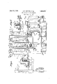
- Fig. 1 of the drawings illustrates two vapor phase cracking systems with refining towers, condensers and connections therebetween in which corresponding parts of the two systems are identified by the same reference numerals with the letter a or bmafppended thereto.
- Fig. 2 of the drawings illustrates the heating coil and furnace of a second vapor phase cracking system adapted to be associated with the apparatus illustrated in Fig. 1 by connecting the lines 3b and 166 as shown at A-A and B-B.
- the heating coil and fur.- nace illustrated in Fig. 2 are identical with that illustrated in Fig. 1 and therefore arev not separately described.
- each ofthe cracking systems in the apparatus illustrated includes a heating conduit 1 coror discharging the balance through the stack 12.
- Fan 11 is provided for supplying the air required for combustion through a preheating heat exchanger in the stack 12.
- the oil may be heated to a dis'- charge temperature approximating, for example, 1000-11000'F.
- the oil may be supplied to the heating conduit under a pres-4 sure just suiiicient to force the-oil .and the oil products through the heating 'conduit and through the rest of the apparatus, 60-80 pounds per square inch, for example.
- each of the cracking systems of the group in the apparatus illustrat- -ed includes such a heating conduit and heating furnace similarly arranged and similarly connected.
- vapor phase ycracking apparatus may be used in carrying out the in-' vention; for example that described in an application filed June 13, 1927, by Harry L. Pelzer, Serial No. 198,621.
- each of the cracking systems inthe appa- -ratus illustrated also includes4 a scrubbing tower 4a, 4b, etc. for the separation of tar and tarryl matter and a reflux tower or fractionat-y ing tower 5a, 5b, etc.
- the hot oil products from each heating conduit are dischar ed into the lower end of the connected scrubbing tower through a liquid pool of tar maintained therein', the vapors escaping from the upper end of the scrubbing tower are discharged into the lower end of thelreiux tower or fracn tionating'tower through connections 6a, 6b, etc., and the vapors escaping from the upper end of the reflux tower or fractionating tower are discharged into one or the other of a pair of manifolds 7 and 8, through connections 13a, 13b, etc.
- Tar and tarry matter are discharged from the lower ends of the scrublmi;
- each scrubbing tower and 'of' each fractionating tower' or reflux towerl may be controlled - ⁇ or in part controlled by means of dephlegmators 20a, 200, etc. mounted on towers a, 5b, etc. Water or other extraneous cooling medium or the raw A and the operation of the .towers controlled 5b, etc. are withV by regulating the rate of circulation of the cooling medium therethrough.
- del phlegmators V may be made a unitary part of the tower structure proper or they may be dispensed with and refluxing provided, for
- the vapor discharge temperature from towers 4a, 4b, etc. may-be maintained in the neighborhood .of 500-550 F. and the vapor discharge temperature from towers 5a, 5b, etc-.'in the neighborhood of 40G-450 F., for
- the towers 4a, 4b, etc. may be of open'bafile construction or of the so-called bubble plate construction, for example.
- the towers 5a, 5b, etc. may be of open'bafile construction or of the so-called bubble plate construction, for example.
- discharge into a receiver 24 maybe termed a ing l condenser.
- the manifold 7 is connected to the upper end of each of a-series of refining towers 26, 27 and 28, through appropriate valved branch connections, and the lower end of each ofthese refining towers is connected, through appropriate valved branch connections, Ito a con'- nection 29 discharging into the fractionating tower 30.
- the upper end of thisfractionattower 30 is connected to a condenser 31 arranged to discharge into a receiver 32.
- This condenser 31 may be termedI a clean
- the fractionating tower 30 is with advan- A tage of bubble plate construction, or other construction adapted-to secure close fractionation.
- the liquid material separated in ⁇ the fractionating towerl 30 is either discharged through connection 33 or, in whole Yor in part, is introduced into the upper end of the4 scrubbing towers 4a, 4b, etc. as a refiuxing agent through connections 34 and 35 by means of pump 36.
- the receiver 32 is connectedto a run down tank 37 for storage of the refined cracked product and the rey l raminous partition in each of the refining towers 26, 27 and 28.
- vapor discharge temperature from tower 30 may be maintained in the neighborhood of 30G-350 F., for example.
- tower 30 may be controlled by the regulated introduction of a reiuxing agent through coiinection'45.
- a part of the refined cracked product may be so supplied to the upper end of tower 30 as a refiuxing agent through connections 46 and 45 by'means of pump 47, or some other refluxing agent, a rened gasoline of corresponding boiling Arange fromv some other operation, for example, may be so supplied as a refluxing agent through connections ⁇ 48 and 45 by means of pump 47.
- the raw cracked vapors including the vapors of the gasoline product fromy each of the vapor phase cracking systems of thev group when in normal operation, are passed through the adsorptive catalyst in the refining towers 26,27 l or 28, the refined vapors are then fractionated to separate a refined gasoline product of the desired boiling range in the fractionating tower30,
- vapors are passed through the refining tower v .produced in condenser 24; being isolated from the condensate produced in condenser 3l.
- the several cracking systems are cut in and cut out of the manifolds 7 and 8 by means of the valves 22a, 22?),v etc., andthe valves 23a, 23o, etc., respectively, to effect such transfers.
- a plurality of refining Ytowers are provided, as illustrated, topermit maintained continuity of the refining operation. Any' one of the group of three illustrated, for eX- ample, can bereut out forcleaning or recharging With fresh catalyst While the other tW-o remain in operation.
- any one of the towers 26, 27 and 28 is cut'outfor cleaning or recharging, it is steamed out through the separate condenser 42.
- the resulting condensate after separation of Water, is isolated from the condensate produced in re-Atitiver 31. tage handled in admixture With that produced in condenser24.
- any oneof the several vapor phase cracking systems is shut downfor cleaning or repair, it
- Unrefined1 ravi1 ⁇ cracked products' from ⁇ other vapor phase cracking 'operations may also be supplled as refluxing agents to fractionating orrefluxing operations in cracking systems operated in accordance with the pres-v ent invention, for example as described. in an application filed herewith by us, Serial No. 305,902.
- .improvement which comprises concurrently conducting. a plurality ofvapor phase cracking operations and, duri-ng normal operation, subjecting the raw vapors from each vapor phase cracking operation to a common refining operation in which the vapors are passed through theadsorptive catalyst, subjecting the thus refined vapors to a common' condensing operation and/collecting there fined condensate, subjecting the' raw lvapors from each vapor phase cracking op eration' to a 'separate common condensing operation Without subjecting them.
- the" improvement which comprises concurrently conducting a plurality .of vapor-phase cracking operations in each-of which the cracked vapors are subjected to a scrubbing opera tion for separation of tar and, during normal operation, subjecting the raW vapors from the scrubbing operation accompanying each vapor phase cracking operation to -fa common refining operation in which the vapors are passed through the adsorptive cata ⁇ P lyst, subjecting theA thus refined vapors to a common condensing operation and collecting the refined condensate, subjecting the raw vapors from each vapor phase cracking operation to a separate common condensing operation Without subjecting them-to the refining operation during the initial and final periods of each vapor phase crackingopera- 'v tion, and completely isolating the condensate and
- a plurality of vapor phase crackingsyst-ems including means for sup-X plying oil thereto, a refining tower adapted iso 69 fractlonating towers with connections adaptto receive a charge of anl adsorptive catalyst and to provide for passage of vapors therethrough, two separate condensers, two separate manifolds -each communicating through valved connections with each of said cracking systems, a connection between one ⁇ of said manifolds and one of said condensers, a connection between the other manifold and the said refining tower and a connection between the said refining tower and the other of said) condensers.
- a plurality of vapor phase cracking systems including means for supply- -ing oil thereto and scrubbing towers through which lthe cracked vapors pass, a refining supplying oil there through which t-h towergadapted to receive a charge of anlad'-, s orptive catalyst and to provide for passage of vapors therethrough, two separatel condensers, two separate manifolds each communicating through valved connections with the scrubbing tower of each of said cracking systems, a connection between one of said manifolds and one of said condensers, a connection between the other manifold and the said refining tower and a connection between the said refining tower and the other of said communicating -through valved connections with each of said condensers, a manifold scrubbing towers and means for supplying high boiling material produced in the said nefiling tower to the 'last mentioned mani- 9.
- a manifold communicating through valved connections with each of said fractionating towers and means for supplying condensate from the first separately mentloned condenser to the last mentioned manifold.
- .fining tower adapted to receive achar e of an 4
Landscapes
- Chemical & Material Sciences (AREA)
- Oil, Petroleum & Natural Gas (AREA)
- Engineering & Computer Science (AREA)
- Chemical Kinetics & Catalysis (AREA)
- General Chemical & Material Sciences (AREA)
- Organic Chemistry (AREA)
- Production Of Liquid Hydrocarbon Mixture For Refining Petroleum (AREA)
Description
April l2, 1932. E. c. HERTHEL ET AL l ART` oF CRACKING HYDRocARBoNs m m mma\ I" .l N LwTHuuh HM HHH S .MMM Nm .uw 3.., @u $1 HHH S? f HVH ..H........H.,`
Patented Apr. 12,1932
- UNITED lSTATES PATENT- OFFICE EUGENE OHERTHEL, OF oHIoAGo, ILLINOIS, AND HARRY L. PELzER, OF HIGHLAND,
INDIANA, AssIGNORs, BY MEsNE ASSIGNMENTS, To THE GRAY riaooEssEs COR- PORATION, or NEWARK, NEW JERSEY, A CORPORATION- OE DELAWARE ART F vGRACKING: HYDROCARBONS Application led September 14, 1928. Serial No. 305,903;`
This invention're'lates to improvements in the manufacture of gasoline; more particularly 'the invention relates to improvements in the combined cracking of oil in vapor phase under severe cracking conditions to produce motor fuelgasoline and refining of the thus produced gasoline by passage through an ad- Asorptive catalyst in vapor phase.
When raw cracked gasoline or a fraction containing raw cracked gasoline, particularly gasoline produced by severe vapor phase' cracking, is passed in vapor phase through an adsorptive catalyst such as fullers earth, certain unsaturated constitutents such as the di-olefines, to the extent that they are present, are polymerized to form higher boiling polymers. This reaction affords a means of separating suchconstituents Without involving loss of other unsaturated constituents of special-value as components of motor fuel gasoline. The separation of the `polymers produced by the vapor-catalyst contact is usually accomplished Aby fractional condensation, liquefaction, either in the refining operation properor in some subsequent fractionating Operation. j
This general method has been employed with considerable success where the proportion of polymers produced in the refining operation approximates- 1/2-1% .by liquid volume of the gasoline product after separation of such polymers, but the raw product from severe vapor phase cracking Operations frequently contains unsaturated constituents reacting with the adsorptive catalyst in' amounts so large that the proportion of polymers produced is as much as 10-1l% by liquid volume of thev gasoline product after separation of such polymers, that is the refining operation must accommodate an amount of polymers ten to twenty times las great as the amount usuallyroduced.
As applied to this type of raw cracked gasoline, the useful period of activity of the adsorptive catalyst becomes of controlling importance because Athe radically increased production of polymers radically shortens the useful period of activity of the 'adsorptive catalyst. Such decrease inthe useful period of activity of the adsorptive catalyst not only i fying the catalyst but also increases the expense of handling the catalyst and the loss ofoperating time involved in replacing spent p catalyst with fresh catalyst.
Where a group of vapor phase cracking systems are Operated concurrently, certain advantages can be secured by treating the raw cracked products from all of the systems of thegroup in a common refining operation. 'lhe apparatus required `is simpler and usually less expensive and the operation is more economical than Where a separate relining operation .is embodied in each of the separate cracking systems. AThe mere connection of a number of cracking systems as a batery to a common refining system, however, imposes added burdens on the adsorptive catalyst used in the refining operation which tend further to shorten its useful period of activity.
Thev present invention provides an im- -proved combined operation in which the raw cracked products from a group of concurrently operated vapor phase cracking systems are refined by passage through an adsorptive catalyst in vapor phase, in acommon refining operation in which the period of activity of the adsorptive catalyst is maintained at a maximum.' The invention also includes an improved apparatus for carrying out this type of refining operation.
According to the present invention, the raw cracked products from a group of vapor phase cracking systems are passed through .an adsorptive catalyst 'in vapor phase in a fect the finished rening of the desired product and its useful period of activity is thus maintained at a maximum. The useful period of activity of the adsorptive catalyst is further .prolonged by the maintenance of uniform operating conditions in the refining Y operation.
As any one vapor phase cracking system of the group is being brought into operation, the raw cracked products therefrom are separately discharged without being passed through the refining operation, and the raw cracked products7 from this system are passed through the refining operation only after the cracking system is in normal operation. Before any one of the cracking systems of the group is shut down, passage of the cracked products therefrom through the refining operation'is'stopped and these cracked products are separately discharged during the shutucts, however, in accordance with the invention, may also' be passed through the common refining operation in a manner avoiding any abnormal burden upon thel adsorptive cata- 1 st. v
y'The invention will be described in connection with the accompanying drawings which illustrate, diagrammatically and conventionally, one form of apparatus embodying-the invention and adapted for carrying out the process of the invention, but it is intended and will be understood that this detailed descripton and illustration are by way of exemplification. l
Fig. 1 of the drawings illustrates two vapor phase cracking systems with refining towers, condensers and connections therebetween in which corresponding parts of the two systems are identified by the same reference numerals with the letter a or bmafppended thereto. The heating coil and furnaceare omitted from one of the systems, however, to avoid unnecessary confusion.
Fig. 2 of the drawings illustrates the heating coil and furnace of a second vapor phase cracking system adapted to be associated with the apparatus illustrated in Fig. 1 by connecting the lines 3b and 166 as shown at A-A and B-B. The heating coil and fur.- nace illustrated in Fig. 2 are identical with that illustrated in Fig. 1 and therefore arev not separately described.
\ Referring to Fig. 1 of the drawings, each ofthe cracking systems in the apparatus illustrated includes a heating conduit 1 varfor discharging the balance through the stack 12. Fan 11 is provided for supplying the air required for combustion through a preheating heat exchanger in the stack 12.
In the heating conduit in lthe apparatus,
illustrated, the oil may be heated to a dis'- charge temperature approximating, for example, 1000-11000'F. The oil may be supplied to the heating conduit under a pres-4 sure just suiiicient to force the-oil .and the oil products through the heating 'conduit and through the rest of the apparatus, 60-80 pounds per square inch, for example.
The-oil products from the heating conduit of each cracking system are discharged through-connections 3a, 3b, etc. To simplify the drawings, but one heating conduit and heating furnaceare shown thereon, but it will be understood that each of the cracking systems of the group in the apparatus illustrat- -ed includes such a heating conduit and heating furnace similarly arranged and similarly connected.
Other types of vapor phase ycracking apparatus may be used in carrying out the in-' vention; for example that described in an application filed June 13, 1927, by Harry L. Pelzer, Serial No. 198,621. A
-Each of the cracking systems inthe appa- -ratus illustrated also includes4 a scrubbing tower 4a, 4b, etc. for the separation of tar and tarryl matter and a reflux tower or fractionat-y ing tower 5a, 5b, etc. The hot oil products from each heating conduit are dischar ed into the lower end of the connected scrubbing tower through a liquid pool of tar maintained therein', the vapors escaping from the upper end of the scrubbing tower are discharged into the lower end of thelreiux tower or fracn tionating'tower through connections 6a, 6b, etc., and the vapors escaping from the upper end of the reflux tower or fractionating tower are discharged into one or the other of a pair of manifolds 7 and 8, through connections 13a, 13b, etc. Tar and tarry matter are discharged from the lower ends of the scrublmi;
bing towers through connections 14a, 146, etc.
to the connected heating conduits throughconnections 16a, etc., 17a, etc., together with raw oil supplied through connections e180i, etc.
by means of pump 19a, etc.
' The operation of each scrubbing tower and 'of' each fractionating tower' or reflux towerl may be controlled -`or in part controlled by means of dephlegmators 20a, 200, etc. mounted on towers a, 5b, etc. Water or other extraneous cooling medium or the raw A and the operation of the .towers controlled 5b, etc. are withV by regulating the rate of circulation of the cooling medium therethrough. These, del phlegmators Vmay be made a unitary part of the tower structure proper or they may be dispensed with and refluxing provided, for
' example, by the direct introduction of a refluxing agent.
In' operation to' produce motor fuel gasoline, the vapor discharge temperature from towers 4a, 4b, etc. may-be maintained in the neighborhood .of 500-550 F. and the vapor discharge temperature from towers 5a, 5b, etc-.'in the neighborhood of 40G-450 F., for
example.
The towers 4a, 4b, etc. may be of open'bafile construction or of the so-called bubble plate construction, for example. The towers 5a,
advantage of bubble plate construction, or other constructionl adapted to secure close fractionation. These towersand dephlegmators as well as the hot connectionsbetween .them'are with advantage lagged or thermally insulated to minimize heat loss and t?) asist in maintaining close control ofthe Y ,v
' The vapor connections 13a, 13b, etc. are
discharge into a receiver 24 maybe termed a ing l condenser.
o eration.
each connected to the manifold 7 through valves 22a, 22?), etc. and to the manifold 8 through valves 23a, 23?), etc. The manifold 8 isconnected toa condenser 24 arranged to 25; This condenserl dirty condenser. The manifold 7 is connected to the upper end of each of a-series of refining towers 26, 27 and 28, through appropriate valved branch connections, and the lower end of each ofthese refining towers is connected, through appropriate valved branch connections, Ito a con'- nection 29 discharging into the fractionating tower 30. The upper end of thisfractionattower 30 is connected to a condenser 31 arranged to discharge into a receiver 32. This condenser 31 may be termedI a clean The fractionating tower 30 is with advan- A tage of bubble plate construction, or other construction adapted-to secure close fractionation. The liquid material separated in `the fractionating towerl 30 is either discharged through connection 33 or, in whole Yor in part, is introduced into the upper end of the4 scrubbing towers 4a, 4b, etc. as a refiuxing agent through connections 34 and 35 by means of pump 36. vThe receiver 32 is connectedto a run down tank 37 for storage of the refined cracked product and the rey l raminous partition in each of the refining towers 26, 27 and 28.
Steam for steaming out therefining towers when they' are cut 'out of operation is supplied through connection 41 and, during the steaming out period, vapors are discharged through a condenser 42 and the resulting condensate through a water separator 43, the
condensate then being discharged into the run down tank 38.
For the production of a gasoline of 400- 410 F. end boiling point, forexample, the
vapor discharge temperature from tower 30 may be maintained in the neighborhood of 30G-350 F., for example.
The operation of tower 30 may be controlled by the regulated introduction ofa reiuxing agent through coiinection'45. A part of the refined cracked product, for example, may be so supplied to the upper end of tower 30 as a refiuxing agent through connections 46 and 45 by'means of pump 47, or some other refluxing agent, a rened gasoline of corresponding boiling Arange fromv some other operation, for example, may be so supplied as a refluxing agent through connections` 48 and 45 by means of pump 47.
In carrying out the invent-ion in the apparatus illustrated, the raw cracked vapors including the vapors of the gasoline product fromy each of the vapor phase cracking systems of thev group, when in normal operation, are passed through the adsorptive catalyst in the refining towers 26,27 l or 28, the refined vapors are then fractionated to separate a refined gasoline product of the desired boiling range in the fractionating tower30,
andthe refined final gas-oline product is conl the initial period of operation and until it is y broughtto normal operating conditions, are condensed in condenser 24 andthe resulting condensate -is isolated from that produced in condenser 31. After that system is brought to normal operating conditions, the
vapors are passed through the refining tower v .produced in condenser 24; being isolated from the condensate produced in condenser 3l. The several cracking systems are cut in and cut out of the manifolds 7 and 8 by means of the valves 22a, 22?),v etc., andthe valves 23a, 23o, etc., respectively, to effect such transfers.
A plurality of refining Ytowers are provided, as illustrated, topermit maintained continuity of the refining operation. Any' one of the group of three illustrated, for eX- ample, can bereut out forcleaning or recharging With fresh catalyst While the other tW-o remain in operation. When any one of the towers 26, 27 and 28 is cut'outfor cleaning or recharging, it is steamed out through the separate condenser 42. The resulting condensate, after separation of Water, is isolated from the condensate produced in re-A ceiver 31. tage handled in admixture With that produced in condenser24. Similarly, When any oneof the several vapor phase cracking systems is shut downfor cleaning or repair, it
issteamed out, through condenser 24, and the result-ing condensate is isolated from the condensate produced 1n condenser` 3l.
The unrefned cracked products condensedfrom vapors which have not been subjected to the refining operations, thecondensate col- 'lecting in-tank 38 in the apparatus illustrated,
are with advantage in carrying out the invention reintroduced into fractionating or refiuxing operations in the cracking system as' refluxing agents, through 'connections 4,9 and by means of pump 5l in the apparatus illustrated,'to be revaporized therein andl subjected to the refining operation in admiX- ture with the vapors from the cracking systems during norma-l operation. By so returning this unrefined raw cracked material to the cracking systems it can be treated as part of the raw products discharged from the cracking systems in normal operation Withoutloss of the constituents it contains suitable as components of the desired product and Withoutadding to the lburden on the adsorptive catalyst disproportionately with respect to the total amountiof refined product produced.
Unrefined1 ravi1` cracked products' from `other vapor phase cracking 'operations may also be supplled as refluxing agents to fractionating orrefluxing operations in cracking systems operated in accordance with the pres-v ent invention, for example as described. in an application filed herewith by us, Serial No. 305,902. Inl the apparatus illustrated, such unrelined' material or some other reflux- This condensate is' with advan- ,eration in admixture with provement which vcomprises concurrently` conducting a plurality of vapor phase cracking `operations in each of Which, the cracked vapors are subjected to a scrubbing operation for separation of tar and, during -normal operation, subjecting the raw vapors from .the scrubibng operation, accompanying each vapor phase cracking operation to a common refining operation in which the vapors are passed through the adsorptive catalyst, sub
jecting the thus refined vapors to a common condensing operation and collectlng the refined condensate, subjecting'the raw vapors l from'eachvapor phase cracking operation to a separate common condensing operation Without subjecting them to the refining operation -during the initial and final .periods of each 'vapor phase cracking operation, and completely isolating the condensate'and the vapors forming the condensate produced in the said separate condensingv operation from the refined condensate and the vapors for1ning the rened condensate produced in the first mentioned condensing operation. A
2. In the combined vapor phase cracking of oil to produce'gasoline and refining'of the thus produced gasoline by passage through an adsorpti've/catalyst Ain vapor phase, the
.improvement which comprises concurrently conducting. a plurality ofvapor phase cracking operations and, duri-ng normal operation, subjecting the raw vapors from each vapor phase cracking operation to a common refining operation in which the vapors are passed through theadsorptive catalyst, subjecting the thus refined vapors to a common' condensing operation and/collecting there fined condensate, subjecting the' raw lvapors from each vapor phase cracking op eration' to a 'separate common condensing operation Without subjecting them. to the refining operation 'during the initial .and final periods of each vapor phase'craoking operation, andlcompletely isolating the condensate and the vapors forming the condensate produced in the said separate .condensing operation' from the refined condensate and the vapors forming the refined condensate produced in the first mentioned condensing operation, and revaporizing condensate produced in the said separate condensing operation by direct introduction into raw vapors from the vapor phase crackingl operations,
during normal operation, to subject the components of thiscondensate to the refiningopf the raw vapors fromthe cracking' operations.
3. In the combined vapor phase cracking of oil to produce gasoline and refining of the thus produced gasoline by passage through an adsorptive catalyst in vapor phase, the
improvement which comprises concurrently conducting a plurality of vapor phase cracking operations in which the cracked vapors are subjected torefluxing operations from, which reflux is returned to. the cracking operations proper and, during normal operation, subjecting the ravvvapors from each vapor phase cracking operation toa common refining operation in Which the .vapors are passed through the adsorptive catalyst, subjecting the thus' refined vapors to a common condensing operation and collecting the refined condensate, subjecting the raw vapors from each vapor phase cracking operation to a separate common condensing operation Without subjecting them to the refining op eration during the initial and final periods of each vapor phase cracking operation, and` completely isolating the condensate and the vapors forming the condensate produced in the said separate condensing operation from the refined condensate and the vapors form.- ing the refined condensate produced in the first mentioned condensing operation, and introducing condensate produced in the said separate condensing operation directly into the said refluxingoperations.
4. In the combined vapor phase cracking of oil to produce gasoline and refining of the .thus 'produced gasoline by passage through an adsorptive catalyst in vapor` phase, the" improvement Which comprises concurrently conducting a plurality .of vapor-phase cracking operations in each-of which the cracked vapors are subjected to a scrubbing opera tion for separation of tar and, during normal operation, subjecting the raW vapors from the scrubbing operation accompanying each vapor phase cracking operation to -fa common refining operation in which the vapors are passed through the adsorptive cata` P lyst, subjecting theA thus refined vapors to a common condensing operation and collecting the refined condensate, subjecting the raw vapors from each vapor phase cracking operation to a separate common condensing operation Without subjecting them-to the refining operation during the initial and final periods of each vapor phase crackingopera- 'v tion, and completely isolating the condensate and the vapors forming the' condensate produced in thesaid separate condensing operation from the refined condensate and the vapors forming the refined condensate produced in the first mentioned condensing operation, and introducing high boiling mal terial produced in the said refining operation directly into the said scrubbing operations. 5. In the combined vapor phase cracking of oil to produce gasoline and refining of the thus produced gasoline by passage through aniadsorptive catalyst in vapor improvement which comprises concurrently conducting a plurality of -vapor phase cra-ck.
ing operations in which the cracked vapors are subjectedY successivelyto scrubbing op-v erations for separation of tar and 13o-refluxing operations from which reflux is returned. to the cracking operations proper and, during normal operation, subjecting the raw vapors,v from each vapor phasecracking opera-y tion to a common refining operation in which the vapors are passed through the adsorptive catalyst, subjecting the thus refined vapors to a common condensing operationand 'collecting the refinedV condensate, subjectin `the raw vapors from each vapor phase crac ing operation to a sepa-rate common condensing operation Without subjecting them to the rephas'e, the
fining operation during the initial and final periods of each vapor phase cracking operation, and completely isolating the condensate produced in the saidseparate condensing opsis eration from the refined condensate and the vapors forming the refined condensate produced in the first mentioned `condensing op-A eration, introducing high boiling 4'material vanv adsorptive catalyst ,in vapor phase, the
improvement which comprises concurrently conducting a plurality of vapor phase cracking operations in each of Which'the cracked vapors are subjected to a scrubbingoperation for separation of tar and, duringnormal op-V eration, subjecting the ravv vapors from the scrubbing operation accompanying each vapor phase cracking operation to a common refining operation in which the vapors are assed through the adsorptive catalyst, subjecting the thus refined vaors to a common fractionating operation a d then t0 a commoncondensing operation and collecting the refined fractionated condensate, subjecting the -ra'vv vapors from each vapor phase crac-k-v ing operation to a separate common condensing operation without subjecting them to the refining operation during the initial'and final periods of each vapor phase cracking operation, and 'completely isolating the conden-l sate and the vapors forming the condensate produced in the said separate condensing operation from the refined condensate'and the vapors forming the -refined condensate produced in the first mentioned condensing operation. l
7 In combination in apparatus for manufacturing gasoline, a plurality of vapor phase crackingsyst-ems including means for sup-X plying oil thereto, a refining tower adapted iso 69 fractlonating towers with connections adaptto receive a charge of anl adsorptive catalyst and to provide for passage of vapors therethrough, two separate condensers, two separate manifolds -each communicating through valved connections with each of said cracking systems, a connection between one` of said manifolds and one of said condensers, a connection between the other manifold and the said refining tower and a connection between the said refining tower and the other of said) condensers.
8. Incombination in apparatus for manufacturing gasoline, a plurality of vapor phase cracking systems including means for supply- -ing oil thereto and scrubbing towers through which lthe cracked vapors pass, a refining supplying oil there through which t-h towergadapted to receive a charge of anlad'-, s orptive catalyst and to provide for passage of vapors therethrough, two separatel condensers, two separate manifolds each communicating through valved connections with the scrubbing tower of each of said cracking systems, a connection between one of said manifolds and one of said condensers, a connection between the other manifold and the said refining tower and a connection between the said refining tower and the other of said communicating -through valved connections with each of said condensers, a manifold scrubbing towers and means for supplying high boiling material produced in the said nefiling tower to the 'last mentioned mani- 9. In combination in apparatus for-manul .tween the said refining tower and 'the other of said condensers, a manifold communicating through valved connections with each of said fractionating towers and means for supplying condensate from the first separately mentloned condenser to the last mentioned manifold.
10. ln combinationin apparatus for manu- .factur1ng\ gasoline, a plurality of vapor Aphase cracking systems including means for supplying oil thereto, scrubbing towers and ed to permit the cracked vapors (to pass in succession therethrough, al refining tower l adaptedto receive a charge of an adsorptive catalyst and to provide for passage of vapors therethrough, two separate .condensers, two
and one of said condensers,
separate manifolds each communicating through valved connections with the fractionating tower of each of said cracking systems, a connection `between one of said manifolds and one ofsaid condensers, a connection between the other manifold and the said refining tower anda connection between the said refining tower andthe other of said conadsorptive catalyst and to provide or passage of vapors. therethrough, `two sepa-rate condensers, two separate manifolds each communicating through valved connections with the scrubbing tower of each of said cracking systems, a connection between one of said manifolds and one of said condensers, -a connection betweenV the other manifold and the said refining tower, a fractionating tower and a connection between the said refining tower and the said fractionating tower, a-connection between the said fractionating tower and the other of said condensers, a manifold communicating through valved connections with each of said scrubbing towers and means for supplying high boiling material separated in the said fractionating tower to the last mentioned manifold.
In testimony whereof we affix our signa-- tures.
' lEUGENE C. HERTHEL.
HARRY L. PELZER.
.fining tower adapted to receive achar e of an 4
Priority Applications (1)
| Application Number | Priority Date | Filing Date | Title |
|---|---|---|---|
| US305903A US1853614A (en) | 1928-09-14 | 1928-09-14 | Art of cracking hydrocarbons |
Applications Claiming Priority (1)
| Application Number | Priority Date | Filing Date | Title |
|---|---|---|---|
| US305903A US1853614A (en) | 1928-09-14 | 1928-09-14 | Art of cracking hydrocarbons |
Publications (1)
| Publication Number | Publication Date |
|---|---|
| US1853614A true US1853614A (en) | 1932-04-12 |
Family
ID=23182866
Family Applications (1)
| Application Number | Title | Priority Date | Filing Date |
|---|---|---|---|
| US305903A Expired - Lifetime US1853614A (en) | 1928-09-14 | 1928-09-14 | Art of cracking hydrocarbons |
Country Status (1)
| Country | Link |
|---|---|
| US (1) | US1853614A (en) |
-
1928
- 1928-09-14 US US305903A patent/US1853614A/en not_active Expired - Lifetime
Similar Documents
| Publication | Publication Date | Title |
|---|---|---|
| US2438467A (en) | Catalytic conversion of hydrocarbons | |
| US1853614A (en) | Art of cracking hydrocarbons | |
| US2380897A (en) | Processing hydrocarbon oils | |
| US1805113A (en) | Art of cracking hydrocarbons | |
| US2205766A (en) | Apparatus for cracking oil | |
| US2074198A (en) | Treatment of hydrocarbon oil | |
| US2175663A (en) | Art of cracking | |
| US2078946A (en) | Conversion of hydrocarbons | |
| US2224570A (en) | Treatment of hydrocarbon oils | |
| US2205765A (en) | Apparatus for cracking oil | |
| US2050847A (en) | Process of treating hydrocarbon oils | |
| US1795067A (en) | Art of refining hydrocarbons | |
| US2099919A (en) | Process for the treatment of hydrocarbon oil | |
| US1811308A (en) | Process and apparatus for producing low boiling point hydrocarbon oils | |
| US2006571A (en) | Process and apparatus for cracking hydrocarbons | |
| US2113816A (en) | Process of treatment of hydrocarbon oil | |
| US1887128A (en) | Art of cracking hydrocarbons | |
| US1950058A (en) | Treating hydrocarbon oils | |
| US1784065A (en) | Method of cracking hydrocarbons | |
| US1948003A (en) | Treating hydrocarbon oils | |
| US2097412A (en) | Process for producing gasoline | |
| US2119409A (en) | Process for the treatment of hydrocarbon oil | |
| US2248842A (en) | Motor fuel production | |
| US2103977A (en) | Treatment of hydrocarbon oils | |
| US2067869A (en) | Process for the treatment of hydrocarbon oils |