US1853613A - Internal combustion engine control mechanism - Google Patents
Internal combustion engine control mechanism Download PDFInfo
- Publication number
- US1853613A US1853613A US243724A US24372427A US1853613A US 1853613 A US1853613 A US 1853613A US 243724 A US243724 A US 243724A US 24372427 A US24372427 A US 24372427A US 1853613 A US1853613 A US 1853613A
- Authority
- US
- United States
- Prior art keywords
- spring
- lever
- valve
- motor device
- pressure
- Prior art date
- Legal status (The legal status is an assumption and is not a legal conclusion. Google has not performed a legal analysis and makes no representation as to the accuracy of the status listed.)
- Expired - Lifetime
Links
Images

Classifications
-
- G—PHYSICS
- G05—CONTROLLING; REGULATING
- G05D—SYSTEMS FOR CONTROLLING OR REGULATING NON-ELECTRIC VARIABLES
- G05D13/00—Control of linear speed; Control of angular speed; Control of acceleration or deceleration, e.g. of a prime mover
- G05D13/08—Control of linear speed; Control of angular speed; Control of acceleration or deceleration, e.g. of a prime mover without auxiliary power
- G05D13/10—Centrifugal governors with fly-weights
Definitions
- My invention relates to governing mechanism of the type employing a speed-changing device and it has for an object to provide improved means for changing the setting of '5 the .speed-changing device.
- I provide means for applying avariable and controllable lforce to the control 'valve lof a motor device, which serves to shift the speed changer, and I arrange for the development of a counterbalancing force due to resulting movement of the motor device.
- a pressure-responsive device may be associated with the control valve of the motor device, the pressure fluid for the pressureresponsive device being a regulable and controllable air pressure, and a spring may be interposed between the valve and the actuatedl motor device provided with a control valve,
- a further object of my invention is to provide remote control speed-changing apparatus for governors of the character indicated wherein each control device is provided with a manually controllable element such that the setting of each speed changer may be controlled manually and independently of the remote control means.
- Fig. 1 is a sectional view of governing mechanism having my improved control means applied thereto;
- Fig. 2 is a diagrammatic view showing the operation of parts' associated with the pilot valve
- Fig. 3 is a detail view showing a manuallyoperated crank for adjusting the speed changer
- Fig. 4 is a partial diagrammatic view showing the relative positions of the parts of the motor device for adjusting the speed changer of the governor when the latter is being actuated by iuid pressure and the engine is operating at an' intermediate s eed;
- Fi 5 is a view similar to Fig. 4, and s owing t e relative positions of parts of the motor device when the speed changer is located at minimum position and when the motor device is being actuated either by fluid pressure or by mechanical means; y
- Fig. 6 is another diagrammatic view showing the relative positions of parts of the motor device when the speed changer is set at an intermediate position and the motor device is being actuated by mechanical means;
- Fig. 8 is a fragmentary, sectional view, taken on the line VIII-VIII'of Fig. 3 and showing the relation of the operating handle with respect to the control linkage, all other portions of the apparatus having been omitted for the sake of clarity.
- I provide a centrifugal governor having a speed changer whose osition is varied by a servomotor device, t e latter being controlled by any suitable elastic Huid whose pressure may be varied.
- Fig. 1' I show a governor of the centrifugal type, at 33, and a speed changer, at 34, the speed changer having its setting varied by operating mechanism indicated generally, at 35. Governing movements for any given speed are transmitted from the governing mechanism, at 33, to any suitabl actuated element or. shaft 36 connected to t e controlling element of a prime mover.
- Centrifugal force applied to the lever 43 is opposed by spring means associated with the speed changer. Hunting effects may be dampened by a dashpot or spring associated with the lever 43.
- I show a spring device 51 for this purpose.
- the speed changer mechanism includes a spring 55 arranged between a follower 56 and a collar 57 on the stem 58, the
- the spring 55 is carried by a sleeve element 62 provided on the oscillato member 63 of the speed changer, the osci latory member being keyed to a supporting shaft 64.
- the follower 56 has threaded engagement with the sleeve 62, whereby the tension of the spring 55 may be suitably varied.
- The'spring 55 has such relative position with respect to the shaft 64 and the track 6() is so curved that both the effective spring force and the effective spring scale are varied so as to secure good regulation throughout the operating speed range of the governor.
- this preferably takes the form of 'a motor device having a cylinder 65 with an operating piston 66 therein.
- the piston 66 is connected to a piston rod 67, the lower portion of which is provided with rack teeth 68 meshing with an idler pinion 69,A which meshes with a sector rack 70 on the oscillatory carrier 63.
- the carrier 63 may be oscillated about the axis of the shaft 64 by upward and downward movement of the o erating piston 66 of the motor device 64. ince theangular position of the shaft 64 is dependent upon the setting of the speed changer, such shaft may exercise a controlling function, that is, be connected to change the timing.
- the motor device is controlled by a pilot valve 72, the latter serving to admit motive fluid to either end of the cylinder 65 and to provide for the exhaust from the other end of such cylinder.
- the upper end of the pilot valve 72 is connected to a piston 73 arranged inthe cylinder 7 3a, having an elastic Huid supply connection 735.
- the pilot valve 72 is, therefore, moved downwardly when the air pressure in the cylinder 7 3a. increases, this resultin 'in the piston portion 74 of the pilot va ve uncovering the cylinder passage 5 and permitting of communication of such assage with the-motive fluid supply line 6, and admitting motive fluid beneath the operating piston 66 to move the latter upwardly.
- Follow-up mechanism is arranged between the piston rod 67 and the pilot valve in order to bring the latter back to neutralcut-otf position.
- the lower end of the pilot valve 72 is pivotally connected to the upper end of a spring 78, the lower end of the spring being pivotally connected, at 7 8a, to a lever 79, the spring being so arranged and connected to the pilot valve and to the lever as to constitute a flexible power-transmitting link between ,such elements.
- the lever 79 has a pivotal connection 80 at one end with respect to thefpiston rod 67.
- the other end of the lever 79 has a pivotal connection 81 with respect to a link 82, the upper end of the latter being supported by an arm 83 having a pivotal connection 84 with respect thereto.
- t e pivotal supporting means 83 is carried b a stub shaft 86 having an outer operating andle 87, as indicated in Fig. 3.
- a stub shaft 86 having an outer operating andle 87, as indicated in Fig. 3.
- the spring 78 is normally not under compression when the arrangement is manually actuated by operating the lever 87, such spring serves a useful purpose in that it provides a yieldable power-transmitting element thereby making it more readily capable oli overcoming friction eifects tending to resist movement of the pilot valve.
- the pivot 84 moves from h to le, the pivot 81 moves from f to i and the pivot 78a moves from b to c during the time that the pivot 8O moves from minimum speed position r to full speed position .s.
- Fig. 1 shows the relative position of "the parts of the motor device when the governor speed changer is y device when the speed changer is set at an intermediate speed, the motor device still being operated by-iluid pressure.
- the handle 87 when the motor device is being operated by fluid pressure, the handle 87 remains fixed in minimum speed position. Therefore, as shown in Fig. 5, when the speed changer is set for minimum speed position, the relative positions of the arts of the motor device including the spring 8, the lever 79, the link 82, and the arm 83 are the same whether the motor device is actuated by fluid pressure or by the handle 87.
- the thrust of the spring 78 serves to counterbalance the pneumatic pressure acting on the piston 73 in the cylinder 7 3a.
- the pivot 84 remains stationary.
- the spring 78 merely serves ⁇ as a flexible Aconnectin link between the lever 79 and the pilot va ve 72.
- valve responsive to controlled elastic fluid pressure and acting in opposition to the spring for moving the valve in the other direction, said valve occupying cut-off position when the opposed spring and fluid pressure forces acting thereon are substantially in equilibrium, follow-up means operated by the actuated element of the motor device for modifying the spring force to bring the latter into substantial equilibrium with the changed elastic Huid pressure force in order to restore the valve to cut-off position, and means for manually operatilg the valve through the spring in order to e ect movement of the actuated element of the motor device throughout the substantial portion of its travel.
- a motor device having an actuated element
- a valve movable in opposed directions to secure cut-of and operation of the motor device in both directions
- a spring for moving the valve in one direction
- follow-up means including a lever connected to the actuated element of the motor device and operatively connected to the spring, pivotal supporting means for said lever spaced from the connection thereof with respect to the spring, whereby, when the lever is moved by the actuated element,
- said valve occupying-fcutfoi.positiony when the opposed springfand'filuidf' rassure' actuated element means so as to eiect manual manipulation of the valve, whereby said valvemay be ac.
- a movable member emcooperating with. the cylsaid va ve portion device to control the adinder ofthe motor cooperating with the piston;V portion of ⁇ the "movable member to form apressurerespom 'said latter .cylinder having a sive.
- p port for the admissionk of elastic ⁇ fluid, fol-f low-up mechanism including ⁇ a' lever pivotally connected at one portion to thel actuated element of the motor device, a spring for connecting another portion of'ftllelever to the movable member, supporting means for tion of said supporting means and means for changing the posiy so as to eect manipulation of the valve, whereby said valve may be actuated independently of said the lever,
- a. motor. device having Y al1-actuated element, a valve forcontrolhng the motor device, a pressure're'sponsive device including a movable element engaging l v theA same, a spring engaging theother-E end 'of the valve for. opposing1 movement of the .movable member of t e pressure respo follow-upv the porting means for the lever,
- ⁇ I isivedevice, -A mechanism includinga'lever op eratively connectedt'o thej actuated element nng,sup
Landscapes
- Physics & Mathematics (AREA)
- General Physics & Mathematics (AREA)
- Engineering & Computer Science (AREA)
- Automation & Control Theory (AREA)
- Mechanically-Actuated Valves (AREA)
Description
H, T. HERR April 12, v1932.
INTERNAL COMBUSTION ENGINE CONTROL MECHNISM 192'." 3 Sheets-Sheet Filed Dec. 50
WITNESS ATTORNEY April l2, 1932. HIT, HERR I INTERNAL ColBUsTIoN ENGINE CONTROL MEcHANIsM Filed Dec. 30, 192'? 3 Sheets-Shea?I 2 ATTORN EY H. T. HERR INTERNAL COMBUSTION ENGINE CONTROL MECHANISM April 12, 1932.
3 Ysheets-sheet 5 Filed Dec`. 30. 1927 INVENTOR ATTORNEY Patented Apr. 1 2, 1932 UNITED STATI-:s PxnazNr OFFICE HERBERT T. HERR, F MERION, PENNSYLVANIA, ASSIGNOR TO WESTINGHOUSE ELEC- TIR-IC & MANUFACTURING COMPANY, A CORPORATION/ 0F PENNSYLVANIA INTERNAL COMBUSTION ENGINE CONTROL MECHANISM.'
Application mea December ao, 1927. serial No.'24s,7,24.
My invention relates to governing mechanism of the type employing a speed-changing device and it has for an object to provide improved means for changing the setting of '5 the .speed-changing device.
I am aware of a type of governing mechanism which has been developed for application to an internal combustion engine, this governing mechaism being characterized by the employmet of a lever, the centrifugal effort of Hy-balls or weights being exerted `upon one side' of the lever and such effort being opposed by spring force applied to the other side of the lever. With this type of governor, the speed-changing or spring device is shiftable along the lever for the purpose of securing a suitable speed ranfre and, at the same time, to provide for sucIi variation in effective spring scale as to secure goodregulation throughout the range of speeds. A governor of this type is capableof operating over a fairly wide range of speeds. Forexample, it may be applied to a Diesel engine v for givin a governing speed range to the g5 latter of Imm about 200 R. P. M. to about 1000 R. P. M. Such a governor is characterized by a speed changer which is shiftable along the governor lever, this shifting being effected by any suitable operating mechanism; and, as developed this operating mechanism takes the form o a servo-motor whose valve element is manually actuated. In accordance with my invention, I have modified the existing governor arrangement and added elementsthereto, such that the operating mechanism for shifting the speed changer may bewcontrolled ironia-distance, thereby making it possible to control the speeds of a plurality of engines fromasingle and re- 40 mote point. This is partlcularly desirable where the engines are mounted on railway cars and connected, respectively, by electric propulsion means to the traction wheels of the respective cars. -Moreparticularly, I
I provide means for applying avariable and controllable lforce to the control 'valve lof a motor device, which serves to shift the speed changer, and I arrange for the development of a counterbalancing force due to resulting movement of the motor device. For example,
a pressure-responsive device may be associated with the control valve of the motor device, the pressure fluid for the pressureresponsive device being a regulable and controllable air pressure, and a spring may be interposed between the valve and the actuatedl motor device provided with a control valve,
the latter being actuated by-a variable and controllable air pressure and a spring being employed to oppose such movement and to apply to the valve a force determined by movement of the motor device, for counterbalancing the force due to the pressure-responsive device. v
A further object of my invention is to provide remote control speed-changing apparatus for governors of the character indicated wherein each control device is provided with a manually controllable element such that the setting of each speed changer may be controlled manually and independently of the remote control means.
These and .other objects are eHected by my invention as will be apparent from the following description and claims taken in connection with the accompanying drawings, forming a-part of this applicatiomin which:
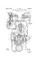
Fig. 1 is a sectional view of governing mechanism having my improved control means applied thereto;
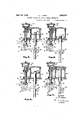
Fig. 2 is a diagrammatic view showing the operation of parts' associated with the pilot valve;
Fig. 3 is a detail view showing a manuallyoperated crank for adjusting the speed changer;
Fig. 4 is a partial diagrammatic view showing the relative positions of the parts of the motor device for adjusting the speed changer of the governor when the latter is being actuated by iuid pressure and the engine is operating at an' intermediate s eed;
Fig. 6 is another diagrammatic view showing the relative positions of parts of the motor device when the speed changer is set at an intermediate position and the motor device is being actuated by mechanical means;
Fig. 7 is still another diagrammatic view of the motor device when the speed changer is set at maximum position and the motor device is being actuated by mechanical means; and,
Fig. 8 is a fragmentary, sectional view, taken on the line VIII-VIII'of Fig. 3 and showing the relation of the operating handle with respect to the control linkage, all other portions of the apparatus having been omitted for the sake of clarity.
In accordance with my invention, I provide a centrifugal governor having a speed changer whose osition is varied by a servomotor device, t e latter being controlled by any suitable elastic Huid whose pressure may be varied.
In Fig. 1', I show a governor of the centrifugal type, at 33, and a speed changer, at 34, the speed changer having its setting varied by operating mechanism indicated generally, at 35. Governing movements for any given speed are transmitted from the governing mechanism, at 33, to any suitabl actuated element or. shaft 36 connected to t e controlling element of a prime mover.
Referring now to the governing mechanism, at 33, I show a rotary carrier 37 connected by gearing 38 to a prime mover shaft 39. The carrier has plvotally connected thereto centrifugal weights 40 which vact upon the lower end of kthe spindle 42, the upper end of the spindle being arranged to transmit the centrifugal effort to the lower side of the lever 43 fulcrumed at 44 and having its other end pivotally connected, at 45, to the pilot valve 46 for the operating piston 47, the latter being connected, in any suitable manner, to an actuated shaft 36. In the drawings, I show rack teeth 48 on the operatin piston 47 and which mesh with similarly ormed teeth on the sector 49 carried by the actuated shaft 36.
Centrifugal force applied to the lever 43 is opposed by spring means associated with the speed changer. Hunting effects may be dampened by a dashpot or spring associated with the lever 43. In the drawings, I show a spring device 51 for this purpose.
The speed changer mechanism, at 34, includes a spring 55 arranged between a follower 56 and a collar 57 on the stem 58, the
the extreme left-hand end of the track 60,'
minimum centrifugal force is opposed by minimum spring force, and the governor is therefore set for minimum speed. On the other hand, with the roller 59 in the position shown in full lines, maximum spring force is yeffective to oppose centrifugal force and,
therefore, the governor has a maximum speed setting. Y
The spring 55 is carried by a sleeve element 62 provided on the oscillato member 63 of the speed changer, the osci latory member being keyed to a supporting shaft 64. The follower 56 has threaded engagement with the sleeve 62, whereby the tension of the spring 55 may be suitably varied. The'spring 55 has such relative position with respect to the shaft 64 and the track 6() is so curved that both the effective spring force and the effective spring scale are varied so as to secure good regulation throughout the operating speed range of the governor.
Referring now to the means, at 35, for changing the setting of the speed changer, at 34, this preferably takes the form of 'a motor device having a cylinder 65 with an operating piston 66 therein. The piston 66 is connected to a piston rod 67, the lower portion of which is provided with rack teeth 68 meshing with an idler pinion 69,A which meshes with a sector rack 70 on the oscillatory carrier 63. Hence, it will be seen that the carrier 63 may be oscillated about the axis of the shaft 64 by upward and downward movement of the o erating piston 66 of the motor device 64. ince theangular position of the shaft 64 is dependent upon the setting of the speed changer, such shaft may exercise a controlling function, that is, be connected to change the timing.
The motor device is controlled by a pilot valve 72, the latter serving to admit motive fluid to either end of the cylinder 65 and to provide for the exhaust from the other end of such cylinder. The upper end of the pilot valve 72 is connected to a piston 73 arranged inthe cylinder 7 3a, having an elastic Huid supply connection 735. The pilot valve 72 is, therefore, moved downwardly when the air pressure in the cylinder 7 3a. increases, this resultin 'in the piston portion 74 of the pilot va ve uncovering the cylinder passage 5 and permitting of communication of such assage with the-motive fluid supply line 6, and admitting motive fluid beneath the operating piston 66 to move the latter upwardly. Concurrently with the placing of the cylinder passa-ge 75 in communication with the motive Huid supply, the cylinder passage 77 is placed in communication with the exhaust, whereby the operating piston 66 may move upwardly. v
Follow-up mechanism is arranged between the piston rod 67 and the pilot valve in order to bring the latter back to neutralcut-otf position. As shown in Figs. 1 and 2, the lower end of the pilot valve 72 is pivotally connected to the upper end of a spring 78, the lower end of the spring being pivotally connected, at 7 8a, to a lever 79, the spring being so arranged and connected to the pilot valve and to the lever as to constitute a flexible power-transmitting link between ,such elements.
The lever 79 has a pivotal connection 80 at one end with respect to thefpiston rod 67. The other end of the lever 79 has a pivotal connection 81 with respect to a link 82, the upper end of the latter being supported by an arm 83 having a pivotal connection 84 with respect thereto.
With this arrangement, Whenever the pressure of elastic fluid, for example, air, supplied tothe cylinder 3a by the line 736 is varied, the pilot valve moves in a direction determined by the change in air pressure. It will be apparent that the lever 79 can not move until it is moved by the operating piston rod 67 for the pivotal connections 80 and 84 are maintained fixed for the time being; however, as soon as the operating piston starts to move, the lever 79 is moved so as to change the force of the spring 78, `this movement continuing until the spring force has been changed to such a value as to counterbalance the air pressure force applied to the pilot valve.
If is desired to set the speed changer for minimum speed, the air pressure in the cylinder 73a is reduced, thereby resulting in upward movement of the pilot. valve 72 due tothe force of the spring 78. Such upward movement of the pilot valve results immediately in downward movement of the operating piston 66 and the latter results in lowering of the lever 79 so as to .diminish the force of the spring 78. `Movement of this character will continue until the spring force and the force due to the air pressure are in balance and the pilot valve occupies cut-ofi:I position. On the other hand, if the air pressure in the cylinder 7 Sais increased, the operating piston 66 will be caused to move upwardly, resulting in compression of the spring 78 and upward movement of the operating piston 66 will continue until the force of the spring 78 is in balanced relation with respect to the force of the pressure fluid effective on the pilot valve.
Referring now to the means for controlling the speed changer independently of the fluld ressure control means, it will be seen that t e pivotal supporting means 83 is carried b a stub shaft 86 having an outer operating andle 87, as indicated in Fig. 3. When ective and the handle 86 actuated from its upper minimum speed position to its lower maxlmum speed position. When the handle 86 is actuated in this way, it will be apparent that the pivotal connection 84 for the upper end of the link 82 is raised and lowered,
therebycausing the lever 79 to fulcrum about the pivotal connection 80. This results in movement of the pilot valve to admit motive fluid to the operatlng cylinder and the resulting movement ofthe operating cylinder operates through the lever 79 and the spring 7 8, the latter serving as a motion-transmitting link, to bring the pilot valve back to neutral, cut-off position.
llfhile the spring 78 is normally not under compression when the arrangement is manually actuated by operating the lever 87, such spring serves a useful purpose in that it provides a yieldable power-transmitting element thereby making it more readily capable oli overcoming friction eifects tending to resist movement of the pilot valve.
Upon reference to diagrammatic Fig. 2, the various movements taking place will be more apparent. Position 1' indicates the minimum speed position of the pivot connection 8O while s indicates the full speed position thereof. The position h is the position of the pivot 84' for fluid pressure or pneumatic operation. As the pivot 84 is xed when the pilot valveis operating pneumatically, the curved line bd represents the path of movement of the pivot 78a from minimum to Vfull speed positions. Concurrently with the latter movement, the pivot 81 moves along the line fe.
If the apparatus is manually actuated, the pivot 84 moves from h to le, the pivot 81 moves from f to i and the pivot 78a moves from b to c during the time that the pivot 8O moves from minimum speed position r to full speed position .s.
The foregoing may be more readily comprehended by a comparison of Figs. 1 and 4 to 7 Referring now to Fig. 1, this shows the relative position of "the parts of the motor device when the governor speed changer is y device when the speed changer is set at an intermediate speed, the motor device still being operated by-iluid pressure. From this'figure,
it will be notedthat the operating piston v66 has assumed an intermediate position in the cyllnder 65 while the compression of the Spring 78h35 been Somewhat lessened. Re- 133 pressive orce acting thereon. Attention isinvited to the fact that, the pivot 84, connecting the link 82 and the arm 83, remains stationary as longv as `the device is being operated by duid pressure. However, in' order to effect mechanical manipulation of the motor device, the pivot 84 is moved.
As stated heretofore, when the motor device is being operated by fluid pressure, the handle 87 remains fixed in minimum speed position. Therefore, as shown in Fig. 5, when the speed changer is set for minimum speed position, the relative positions of the arts of the motor device including the spring 8, the lever 79, the link 82, and the arm 83 are the same whether the motor device is actuated by fluid pressure or by the handle 87.
. However, as the handle 87 is moved away from minimum speed position, the parts assume the relative positions shown in Fig. 6. It will be noted that manual control, that is, manipulation ofthe handle 87, has resulted in lowering the pivot 84. During the lowering of the pivot 84, the spring 78 merely serves as a flexible connection between the lever 79 and the pilot valve 72 to cause the latter to be temporarily displaced and to permit motive fluid to enter the upper end 'of the cylinder until such time as the rod 67 has moved downwardly a suilicient distance tov return the pilot valve 72 to its static or cut-off position. Referring nowto Fig. 7, this shows the maximum speed position for the motor device when the latter is being actuated by the handle 87.
From the foregoing, it will be apparent that, during operation by fluid pressure,
the thrust of the spring 78 serves to counterbalance the pneumatic pressure acting on the piston 73 in the cylinder 7 3a. As long as Huid-pressure operation takes place, the pivot 84 remains stationary. However, when operation by means of the handle 87 takes place, the pivot 84 is moved and the spring 78 merely serves `as a flexible Aconnectin link between the lever 79 and the pilot va ve 72.
From the foregoing, it will be ap arent that I have devised a governor inclhding a. s d changer togetherV with operating mec anism for changing the setting of the speed changer, the operating mechanism including a servo-motor having a pilot valve moved in one directionby a spring and moved in the other direction y pressure of elastic fluid. The arrangement is such that in case of movement of the pilot valve due to change in pressure of the controlling elastic fluid, the actuated element-of the servomotor causes the force of the spring to change so that the latter may be brought into equilibrium with the changed elastic duid lpressure force andthe valve restored to cut-oif position. In addition, due to the interpositionof the spring between the pilot valve and the follow-up lever, this permitting of the operation just referred to, the pivotal connection for the lever may be moved manually in order that the servo-motor may be manually controlled.
While I have shown my invention in but one form, it will be obvious to those skilled in the art that it is not so limited, but is susceptible of various changes and modifications, without departing from the spirit thereof, and I desire, therefore, that only such limitations shall be placed thereupon as are imposed by the prior art or as are speciiically set forth in the appended claims.
What I Aclaim is:
1. In apparatus of the character described,
responsive to controlled elastic fluid pressure and acting in opposition to the spring for moving the valve in the other direction, said valve occupying cut-off position when the opposed spring and fluid pressure forces acting thereon are substantially in equilibrium, follow-up means operated by the actuated element of the motor device for modifying the spring force to bring the latter into substantial equilibrium with the changed elastic Huid pressure force in order to restore the valve to cut-off position, and means for manually operatilg the valve through the spring in order to e ect movement of the actuated element of the motor device throughout the substantial portion of its travel.
2. In apparatus of the character described, the combination of a motor device having an actuated element, a valve movable in opposed directions to secure cut-of and operation of the motor device in both directions, a spring for moving the valve in one direction, means responsive to controlled fluid pressure and acting in opposition to the spring to secure movement of the valve in the other direction, said valve occupying cut-off vposition when the opposed spring and fluid pressure forces acting thereon are substantially in equilibrium, follow-up means including a lever connected to the actuated element of the motor device and operatively connected to the spring, pivotal supporting means for said lever spaced from the connection thereof with respect to the spring, whereby, when the lever is moved by the actuated element,
the spring force is brought into equilibrium" the combination of a motor device having an actuated element, a val'v'efy movable in opposed directions to secure'cut-oi `and operation of the motor device in both direction, a
4s rin Afor movin the valve' inone' direction P g g v means responsive to controlled fluid' pressure and acting in opposition tothev spring to secure operation of the valve in the-other direc- Y lequiiilmium,
' changed' fluid pressure v bodyin a piston portionand `a valve portion,
f mission of motive tion, said valve occupying-fcutfoi.positiony when the opposed springfand'filuidf' rassure' actuated element means so as to eiect manual manipulation of the valve, whereby said valvemay be ac.
tuated independently of pressure responsive means, y
In testimony whereof, I have hereunto subscribed my name this 13th day of December,
HERBERT lT. HERR forces 'acting thereonare."substantially inA follow-upfnleansgi-ncluding a lever pivotally connected:atjj0.11.25.;luidtof-the`` A and conngait-,ed jijnltermmi-f ately of its length to said vI'Jivotal s'up-v po means for the otherfefnd" ofsthe'lever, I
the actuated element lof the .mtortdelvi op' erating the lever about saidi-pivotalfsupportin means brlng the'latter into e Store the valve to cut-of po ual means for moving sa1d?pivotal'support ling means in order to-s'ecuremanualcontrol ofthe motor device..
, 4. In apparatus of the actuated element, a movable member emcooperating with. the cylsaid va ve portion device to control the adinder ofthe motor cooperating with the piston;V portion of` the "movable member to form apressurerespom 'said latter .cylinder having a sive. device, p port for the admissionk of elastic `fluid, fol-f low-up mechanism including` a' lever pivotally connected at one portion to thel actuated element of the motor device, a spring for connecting another portion of'ftllelever to the movable member, supporting means for tion of said supporting means and means for changing the posiy so as to eect manipulation of the valve, whereby said valve may be actuated independently of said the lever,
- pressure responsive device.
v one end of the valve for actuating 5. AIn apparatus of the character described, v
to modiythel-Ispringrforceto n uilibrium .with the'. orce in. orde'rto resitimrl;allllnvncharacter the combination of a motor4 device having an v fluid thereto,*'a.cy1inder wfg..
the combination of a. motor. device having Y al1-actuated element, a valve forcontrolhng the motor device, a pressure're'sponsive device including a movable element engaging l v theA same, a spring engaging theother-E end 'of the valve for. opposing1 movement of the .movable member of t e pressure respo follow-upv the porting means for the lever,
`I isivedevice, -A mechanism includinga'lever op eratively connectedt'o thej actuated element nng,sup
changing the position of said supporting lso f
Priority Applications (1)
| Application Number | Priority Date | Filing Date | Title |
|---|---|---|---|
| US243724A US1853613A (en) | 1927-12-30 | 1927-12-30 | Internal combustion engine control mechanism |
Applications Claiming Priority (1)
| Application Number | Priority Date | Filing Date | Title |
|---|---|---|---|
| US243724A US1853613A (en) | 1927-12-30 | 1927-12-30 | Internal combustion engine control mechanism |
Publications (1)
| Publication Number | Publication Date |
|---|---|
| US1853613A true US1853613A (en) | 1932-04-12 |
Family
ID=22919868
Family Applications (1)
| Application Number | Title | Priority Date | Filing Date |
|---|---|---|---|
| US243724A Expired - Lifetime US1853613A (en) | 1927-12-30 | 1927-12-30 | Internal combustion engine control mechanism |
Country Status (1)
| Country | Link |
|---|---|
| US (1) | US1853613A (en) |
Cited By (8)
| Publication number | Priority date | Publication date | Assignee | Title |
|---|---|---|---|---|
| US2458398A (en) * | 1943-12-08 | 1949-01-04 | Bendix Aviat Corp | Engine speed control |
| US2466438A (en) * | 1943-05-01 | 1949-04-05 | Kalin Albert | Governor |
| US2481020A (en) * | 1945-10-31 | 1949-09-06 | Fairbanks Morse & Co | Engine control means |
| US2597815A (en) * | 1947-08-21 | 1952-05-20 | Worthington Pump & Mach Corp | Hydraulic booster and lever means for conveying speed control signals to a control lever for speed governors, throttles, or the like |
| US2648533A (en) * | 1947-11-04 | 1953-08-11 | Caterpillar Tractor Co | Centrifugal type governor having hydraulically assisted speed setting control |
| US2880984A (en) * | 1955-01-20 | 1959-04-07 | Hoof Products Company | Spring adjustment assembly for engine regulator |
| US2924200A (en) * | 1953-03-04 | 1960-02-09 | Westinghouse Electric Corp | Aircraft flight control apparatus |
| US3075350A (en) * | 1958-12-19 | 1963-01-29 | Bendix Corp | Gas turbine fuel control including timing device for scheduling acceleration |
-
1927
- 1927-12-30 US US243724A patent/US1853613A/en not_active Expired - Lifetime
Cited By (8)
| Publication number | Priority date | Publication date | Assignee | Title |
|---|---|---|---|---|
| US2466438A (en) * | 1943-05-01 | 1949-04-05 | Kalin Albert | Governor |
| US2458398A (en) * | 1943-12-08 | 1949-01-04 | Bendix Aviat Corp | Engine speed control |
| US2481020A (en) * | 1945-10-31 | 1949-09-06 | Fairbanks Morse & Co | Engine control means |
| US2597815A (en) * | 1947-08-21 | 1952-05-20 | Worthington Pump & Mach Corp | Hydraulic booster and lever means for conveying speed control signals to a control lever for speed governors, throttles, or the like |
| US2648533A (en) * | 1947-11-04 | 1953-08-11 | Caterpillar Tractor Co | Centrifugal type governor having hydraulically assisted speed setting control |
| US2924200A (en) * | 1953-03-04 | 1960-02-09 | Westinghouse Electric Corp | Aircraft flight control apparatus |
| US2880984A (en) * | 1955-01-20 | 1959-04-07 | Hoof Products Company | Spring adjustment assembly for engine regulator |
| US3075350A (en) * | 1958-12-19 | 1963-01-29 | Bendix Corp | Gas turbine fuel control including timing device for scheduling acceleration |
Similar Documents
| Publication | Publication Date | Title |
|---|---|---|
| US2228239A (en) | Control for superchargers | |
| US1853613A (en) | Internal combustion engine control mechanism | |
| US2053797A (en) | Fluid operated regulating machine | |
| US1585170A (en) | Balanced system of control | |
| US2106684A (en) | Governor | |
| US1533767A (en) | Governor | |
| US2252838A (en) | Governor | |
| US1641196A (en) | Measuring system | |
| US2168155A (en) | Governing system for elastic fluid engines | |
| US2630814A (en) | Stability of hydraulic turbine regulators | |
| US2579643A (en) | Manual and automatic control apparatus for combustion engines | |
| US1891096A (en) | Speed governing mechanism | |
| US2931375A (en) | Governor for constant speed drives | |
| US2439325A (en) | Governing arrangement with servomotor | |
| US1384314A (en) | Speed-responsive device | |
| US2473449A (en) | Centrifugal governor | |
| US2246169A (en) | Governing mechanism for elastic fluid turbines | |
| US3112406A (en) | Governor system | |
| US2113416A (en) | Governing mechanism for elastic fluid turbines | |
| US2111420A (en) | Governing mechanism for elastic fluid turbines | |
| US1905760A (en) | Elastic fluid turbine | |
| US1154062A (en) | Speed-governing mechanism. | |
| US1887536A (en) | Fluid pressure governing mechanism | |
| US1231261A (en) | Governor. | |
| US2224638A (en) | Prime mover control system |