US1853601A - Car truck construction - Google Patents
Car truck construction Download PDFInfo
- Publication number
- US1853601A US1853601A US220797A US22079727A US1853601A US 1853601 A US1853601 A US 1853601A US 220797 A US220797 A US 220797A US 22079727 A US22079727 A US 22079727A US 1853601 A US1853601 A US 1853601A
- Authority
- US
- United States
- Prior art keywords
- bolster
- side frame
- springs
- spring
- removable
- Prior art date
- Legal status (The legal status is an assumption and is not a legal conclusion. Google has not performed a legal analysis and makes no representation as to the accuracy of the status listed.)
- Expired - Lifetime
Links
- 238000010276 construction Methods 0.000 title description 7
- 230000000670 limiting effect Effects 0.000 description 9
- 240000000724 Berberis vulgaris Species 0.000 description 2
- 241000157282 Aesculus Species 0.000 description 1
- 229910000831 Steel Inorganic materials 0.000 description 1
- 230000006835 compression Effects 0.000 description 1
- 238000007906 compression Methods 0.000 description 1
- 235000010181 horse chestnut Nutrition 0.000 description 1
- 239000000463 material Substances 0.000 description 1
- 230000004048 modification Effects 0.000 description 1
- 238000012986 modification Methods 0.000 description 1
- 239000010959 steel Substances 0.000 description 1
Images
Classifications
-
- B—PERFORMING OPERATIONS; TRANSPORTING
- B61—RAILWAYS
- B61F—RAIL VEHICLE SUSPENSIONS, e.g. UNDERFRAMES, BOGIES OR ARRANGEMENTS OF WHEEL AXLES; RAIL VEHICLES FOR USE ON TRACKS OF DIFFERENT WIDTH; PREVENTING DERAILING OF RAIL VEHICLES; WHEEL GUARDS, OBSTRUCTION REMOVERS OR THE LIKE FOR RAIL VEHICLES
- B61F5/00—Constructional details of bogies; Connections between bogies and vehicle underframes; Arrangements or devices for adjusting or allowing self-adjustment of wheel axles or bogies when rounding curves
- B61F5/02—Arrangements permitting limited transverse relative movements between vehicle underframe or bolster and bogie; Connections between underframes and bogies
- B61F5/04—Bolster supports or mountings
- B61F5/12—Bolster supports or mountings incorporating dampers
Definitions
- a further object is to provide a construction in which a removable member is so located between the springs and the bolster spring seat, that saidmember will be always 20 under load and to this extent will not be subject to the conditions of vibration and rattling, which might result from the employment of a loose piece bolted to the bolster.
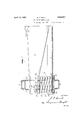
- Figure 1 is a view partly in elevation and partly in section, showing portions of a truck bolster, side frame, spring plank and springs and disclosing an embodiment of my inve tlon';
- Each side frame comprises a lower or tension member 2, an
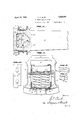
- FIG. 1 is a view showing the truck bol-' Figure 4 is a separate view of the remov- Serial N0. 220,797.
- the two side frames (only one of which is indicated in the drawings) are connected by a springplank 8, the end portions of which project through the openings of the side frames and rest upon the central portions of the tension members and also upon horizontal flanges 9, 10 which project from respective sides of the central portion of the tension member of each side frame.
- Each flange-9, 10, is provided with depressions 11 which receive bosses 12 depending from the spring plank, each of said bosses on the spring plank being provided with an opening through which a lug 13 projecting upwardly from the flange 9 or 10 passes.
- the spring plank has removable interlocking relations to each of the side frames, or if desired, removable connection of the spring plank with the side frame may be accomplished by means of separable parts such as bolts, pins or other readily removable devices.
- Each seat portion of the bolster is made with a recess 15 whereby a seat is formed for the reception of a removable plate 16.
- the plate 16 is of such thickness that when in place, its bottom surface will lie flush with the bottom surface of the adjacent portion ofthe bolster
- the bottom surface of the plate constitutes a spring seat as does also the adjacent portion 17 of the bolster.
- Springs 18 bear at their upper ends against the bolster seats 17, while springs 19 bear at their upper ends, for the most part, against the seats afforded by the plate but these springs .19 also overlap portions of the seat 17 and have partial bearings thereagainst.
- a shim 20 may be provided between the upper ends of the-springs.
- the seat portion of the bolster formedbythe base of the recess 15, is formed with sockets or holes 23 which receive lugs or tenons 2 1 projecting upward- 1y from the plate 16. It will be understood, however, that the seat portion of the bolster may be provided with lugs or tenons to enter sockets or holes in the plate 16.
- The'plate 16 is provided at its ends with lugs 25 which project laterally (relatively to the bolster) sufiicient distances to provide outside stops cooperable with the outside faces of the columnsct. If desired, greater bearing surfaces for the lugs or projections 25 may be efiected by providing lugs 26, 27 on the plate 16, as illustrated in Figures 5 and 6.
- the bolster can then be lowered to rest on those springs it normally bears on, and freeing the spring plank from its connection with the side frame, the spring plank, springs and superimposed parts be blocked or held while the side frame can then be moved laterally and thus removed without material disturbance of the other truck parts.
- a side frame a spring plank having its end fitted into the side frame, a bolster fitted in the side frame above the spring plank, and provided with means abutting the side frame for limiting the relatively outward movement of the bolster, removable means for limiting the relatively inward movement of the bolster, said removable means constituting a spring seat held in place by an imposed load, and means for limiting the outward and inward movement of the spring plank, permitting vertical movement of both spring plank and bolster, and whereby the spring plank and bolster may be raised and the side frame withdrawn after the removable means have been removed.
- a side frame a spring plank having its end fitted into the side frame, a bolster fitted in the side frame above the spring plank, and provided with means abutting the side frame for limiting the relatively outward movement of the bolster, removable means for limit-ing the relatively inward movement of the bolster, said removable means constituting a spring seat, and means for limiting the outward and inward movement of the spring plank, permitting vertical movement of both spring plank and bolster, and whereby the spring plank and bolster may be raised and the side frame withdrawn after the removable means have been removed without materially disturbing the relation between the spring plank and bolster.
- each side frame having a central opening to receive an end of the bolster, the latter having inner lateral abutments coacting with the side frames, springs under the bolster to support it, a member connecting the frames at their lower portion and having interlocking relation thereto, removable means cooperable with the ends of the bolster and constituting spring seats and providing outside stops to abut the side frames, whereby after removal of said removable means the side frames may be Withdrawn laterally after they have been relieved of their load without substantial disturbance of the normal relation between the bolster and connecting member, and without disturbance of the inner bolster abutments.
Description
' April 12, 1932. 5, us
CAR TRUCK CONSTRUCTION Filed Sept. 20 1927 2 Sheets-Sheet m m m g April 12, 1932. s. P. BUSH CAR TRUCK CONSTRUCTION Filed Sept. 20. 1927 2 Sheets-Sheet 2 i T v Fir Z7 7 j gwuento'a m 2 Wu 4 2 2 M, ww J %\.m z Mm H m an? F 2/ km m g m 0 a 45 side frames 1 is shown.
Patented Apr. 12, 1932 A ES- orrics SAMUEL P. BUSH, OF COLUMBUS, OHIO, ASSIGNOR' TO THE BUCKEYE STEEL CASTINGS COMPANY, OIE COLUMBUS, OHIO CAR TRUCK cons'rnocrron Application filed September 20, 1927.
10 spring seats and outside stops shall have interlocking relation to the bolster, and. in V which such relation of said member to the bolster shall be maintained and insured by the action of the load pressure, to which said 5 member is constantly subjected.
A further object is to provide a construction in which a removable member is so located between the springs and the bolster spring seat, that saidmember will be always 20 under load and to this extent will not be subject to the conditions of vibration and rattling, which might result from the employment of a loose piece bolted to the bolster.
With these and other objects in view, the
25 invention consists in certain novel features of construction and combinations of parts as hereinafter set forth and pointed out in the claims. 7
In the accompanying drawings:
Figure 1 is a view partly in elevation and partly in section, showing portions of a truck bolster, side frame, spring plank and springs and disclosing an embodiment of my inve tlon';
able plate, and
' Figures 5 and 6 illustrate a modification.
In the embodiment of the invention shown in the drawings, a portion of one of the Each side frame comprises a lower or tension member 2, an
upper or compression member 3, and columns 4, 4 defining a central opening 5, through which an end portion of a bolster 6 passes, I 5 the latter having thereon, integral inside lugs Figure 2 is a view showing the truck bol-' Figure 4 is a separate view of the remov- Serial N0. 220,797.
or guides 7, 7 for cooperation with the columns 4, 4. The two side frames (only one of which is indicated in the drawings) are connected by a springplank 8, the end portions of which project through the openings of the side frames and rest upon the central portions of the tension members and also upon horizontal flanges 9, 10 which project from respective sides of the central portion of the tension member of each side frame. Each flange-9, 10, is provided with depressions 11 which receive bosses 12 depending from the spring plank, each of said bosses on the spring plank being provided with an opening through which a lug 13 projecting upwardly from the flange 9 or 10 passes. In this manner, the spring plank has removable interlocking relations to each of the side frames, or if desired, removable connection of the spring plank with the side frame may be accomplished by means of separable parts such as bolts, pins or other readily removable devices.
' Each seat portion of the bolster is made with a recess 15 whereby a seat is formed for the reception of a removable plate 16. The plate 16 is of such thickness that when in place, its bottom surface will lie flush with the bottom surface of the adjacent portion ofthe bolster The bottom surface of the plate constitutes a spring seat as does also the adjacent portion 17 of the bolster. Springs 18 bear at their upper ends against the bolster seats 17, while springs 19 bear at their upper ends, for the most part, against the seats afforded by the plate but these springs .19 also overlap portions of the seat 17 and have partial bearings thereagainst. If desired a shim 20 may be provided between the upper ends of the-springs. 1819 and the member 16 and seat 17 and said shim may be provided with projections 21 to enter holes or sockets 22 in the member 16 and seat 17. The lower ends of the springs 18, 19 rest upon the spring plank 8. In the embodiment of the invention shown in the drawings, the seat portion of the bolster, formedbythe base of the recess 15, is formed with sockets or holes 23 which receive lugs or tenons 2 1 projecting upward- 1y from the plate 16. It will be understood, however, that the seat portion of the bolster may be provided with lugs or tenons to enter sockets or holes in the plate 16.
The'plate 16 is provided at its ends with lugs 25 which project laterally (relatively to the bolster) sufiicient distances to provide outside stops cooperable with the outside faces of the columnsct. If desired, greater bearing surfaces for the lugs or projections 25 may be efiected by providing lugs 26, 27 on the plate 16, as illustrated in Figures 5 and 6.
With the construction and arrangement of parts hereinbefore described, it will be observed that by locating the removable plate 16 between the bolster and the springs, the plate will be constantly under pressure of the load and its interlocked relation to the bolster will be maintained without the annoyance of rattling due to vibration as would be liable to occur by loosening of a separate plate bolted to the bolster. Furthermore, with the construction herein disclosed, it will be understood that, by jacking up the bolster so that disengagement of the plate 16 from the bolster may be effected, the plate may be slipped completely out. The bolster can then be lowered to rest on those springs it normally bears on, and freeing the spring plank from its connection with the side frame, the spring plank, springs and superimposed parts be blocked or held while the side frame can then be moved laterally and thus removed without material disturbance of the other truck parts.
Having fully described my invention what I claim as new and desire to secure by Letters-Patent, is
1. The combination with a side frame, a bolster entering the same, and springs below the bolster, of a removable member seated under and extending across the end of the bolster and having interlocking relation thereto, said member affording a spring seat maintained in place by pressure of the load to which it is subjected, and outside stops on said member, certain of the springs being positioned to one side of said member and directly supporting the bolster.
2. The combination with a side frame, a bolster entering the same and springs below the bolster, of a removable member between the springs and the end of the bolster and 5 having interlocking relation to the latter, -sa1d member having lugs or pro ections cooperable with the outer side of the side frame, certain of the springs being positioned to one side of said member and directly supporting the bolster.
3. The combination with a side frame having a bolster opening, and springs in the side frame, of a bolster entering the bolster opening, said bolster having a spring seat on its bottom and also having a recess in its bottom entirely across its end and adjacent to said spring seat, a member filling said recess and having interlocking relation to the bolster, the bottom of said member affording a spring seat, and outside lugs on said member and cooperable with the side frame.
at. The combination with a side frame having a bolster opening, of a bolster entering said opening, said bolster having spring seats on its bottom and also having a transverse recess extending entirely across its end, a member seated in said recess and having interlocking relation with the bolster, the bottom of said member affording spring seats in line with the first mentioned spring seats, lugs on V the ends of said member cooperable with the outer side of the side frame, springs bearing upwardly against said member and overlying portions of the first-mentioned spring seats, and other springs bearing upwardly against said first mentioned spring seats.
5. The combination of a side frame, a bolster entering the same, and provided with means, abutting the side frame for limiting the outward movement of the bolster, and removable means for limiting the inward movement of the bolster relatively to the side frame, said removable means also constituting seating means for the upper ends of springs and being flush with the under side of the bolster.
6. The combination of a side frame, a bolster entering the same, means for limiting the outward movement of the bolster, and a removable fiat plate engaging the underside of the bolster at an end portion thereof and forming spring seats fiush with the under side of the bolster, said plate being provided with projections constituting means cooperable with the side frame to limit inward movement of the bolster.
7. In a car truck, a side frame, a spring plank having its end fitted into the side frame, a bolster fitted in the side frame above the spring plank, and provided with means abutting the side frame for limiting the relatively outward movement of the bolster, removable means for limiting the relatively inward movement of the bolster, said removable means constituting a spring seat held in place by an imposed load, and means for limiting the outward and inward movement of the spring plank, permitting vertical movement of both spring plank and bolster, and whereby the spring plank and bolster may be raised and the side frame withdrawn after the removable means have been removed.
8. In a car truck, a side frame, a spring plank having its end fitted into the side frame, a bolster fitted in the side frame above the spring plank, and provided with means abutting the side frame for limiting the relatively outward movement of the bolster, removable means for limit-ing the relatively inward movement of the bolster, said removable means constituting a spring seat, and means for limiting the outward and inward movement of the spring plank, permitting vertical movement of both spring plank and bolster, and whereby the spring plank and bolster may be raised and the side frame withdrawn after the removable means have been removed without materially disturbing the relation between the spring plank and bolster.
9. In a railway car truck, the combination of side frames, a bolster, each side frame having a central opening to receive an end of the bolster, the latter having inner lateral abutments coacting with the side frames, springs under the bolster to support it, a member connecting the frames at their lower portion and having interlocking relation thereto, removable means cooperable with the ends of the bolster and constituting spring seats and providing outside stops to abut the side frames, whereby after removal of said removable means the side frames may be Withdrawn laterally after they have been relieved of their load without substantial disturbance of the normal relation between the bolster and connecting member, and without disturbance of the inner bolster abutments.
In testimony whereof, I have signed this specification.
SAMUEL P. BUSH.
Priority Applications (1)
| Application Number | Priority Date | Filing Date | Title |
|---|---|---|---|
| US220797A US1853601A (en) | 1927-09-20 | 1927-09-20 | Car truck construction |
Applications Claiming Priority (1)
| Application Number | Priority Date | Filing Date | Title |
|---|---|---|---|
| US220797A US1853601A (en) | 1927-09-20 | 1927-09-20 | Car truck construction |
Publications (1)
| Publication Number | Publication Date |
|---|---|
| US1853601A true US1853601A (en) | 1932-04-12 |
Family
ID=22825020
Family Applications (1)
| Application Number | Title | Priority Date | Filing Date |
|---|---|---|---|
| US220797A Expired - Lifetime US1853601A (en) | 1927-09-20 | 1927-09-20 | Car truck construction |
Country Status (1)
| Country | Link |
|---|---|
| US (1) | US1853601A (en) |
-
1927
- 1927-09-20 US US220797A patent/US1853601A/en not_active Expired - Lifetime
Similar Documents
| Publication | Publication Date | Title |
|---|---|---|
| US2031777A (en) | Car truck | |
| US4094253A (en) | Railway truck floating pedestal wear liner | |
| US1853601A (en) | Car truck construction | |
| US2657102A (en) | Guard bearing | |
| US1828280A (en) | Railway truck | |
| US1745679A (en) | Car-truck construction | |
| US2109715A (en) | Railway car truck | |
| US1717045A (en) | Side bearing for car trucks | |
| US1657934A (en) | Truck bolster | |
| US1933458A (en) | Car body side bearing | |
| US1978637A (en) | Car truck bolster lock | |
| US1952378A (en) | Car truck | |
| US1752728A (en) | Car truck | |
| US1983088A (en) | Railway car truck | |
| US569044A (en) | Metallic car-truck | |
| US1708990A (en) | Car-truck construction | |
| US1706783A (en) | Spring plank | |
| US1763222A (en) | Railway truck | |
| US1210549A (en) | Journal-box. | |
| US1336436A (en) | Railway-car | |
| US2871801A (en) | Quick wheel change truck | |
| US702899A (en) | Journal-box. | |
| US1825396A (en) | Car truck | |
| US991697A (en) | Car-truck. | |
| US1228280A (en) | Side bearing for cars. |