US1853597A - Water-pressure reducing device - Google Patents
Water-pressure reducing device Download PDFInfo
- Publication number
- US1853597A US1853597A US566331A US56633131A US1853597A US 1853597 A US1853597 A US 1853597A US 566331 A US566331 A US 566331A US 56633131 A US56633131 A US 56633131A US 1853597 A US1853597 A US 1853597A
- Authority
- US
- United States
- Prior art keywords
- pipe
- water
- casing
- reducing device
- pressure reducing
- Prior art date
- Legal status (The legal status is an assumption and is not a legal conclusion. Google has not performed a legal analysis and makes no representation as to the accuracy of the status listed.)
- Expired - Lifetime
Links
- XLYOFNOQVPJJNP-UHFFFAOYSA-N water Substances O XLYOFNOQVPJJNP-UHFFFAOYSA-N 0.000 description 18
- 230000008878 coupling Effects 0.000 description 11
- 238000010168 coupling process Methods 0.000 description 11
- 238000005859 coupling reaction Methods 0.000 description 11
- 238000004140 cleaning Methods 0.000 description 9
- 238000007599 discharging Methods 0.000 description 2
- 210000002445 nipple Anatomy 0.000 description 2
- 230000002452 interceptive effect Effects 0.000 description 1
- 239000000463 material Substances 0.000 description 1
- 238000012986 modification Methods 0.000 description 1
- 230000004048 modification Effects 0.000 description 1
- NJPPVKZQTLUDBO-UHFFFAOYSA-N novaluron Chemical compound C1=C(Cl)C(OC(F)(F)C(OC(F)(F)F)F)=CC=C1NC(=O)NC(=O)C1=C(F)C=CC=C1F NJPPVKZQTLUDBO-UHFFFAOYSA-N 0.000 description 1
- 238000009428 plumbing Methods 0.000 description 1
- 239000013049 sediment Substances 0.000 description 1
Images
Classifications
-
- B—PERFORMING OPERATIONS; TRANSPORTING
- B08—CLEANING
- B08B—CLEANING IN GENERAL; PREVENTION OF FOULING IN GENERAL
- B08B9/00—Cleaning hollow articles by methods or apparatus specially adapted thereto
- B08B9/02—Cleaning pipes or tubes or systems of pipes or tubes
- B08B9/027—Cleaning the internal surfaces; Removal of blockages
- B08B9/04—Cleaning the internal surfaces; Removal of blockages using cleaning devices introduced into and moved along the pipes
Definitions
- This invention relates to devices for the use of plumbers and pertains particularly to a device for reducing the pressure of water discharging from a pipe line, for the protection of the plumber while he is operating a cleaning device in the pipe.
- the primary object of the present invention is to provide a device which will operate to protect the plumber while cleaning out the pipe line, without in any manner interfering with the operation of the plpe cleaning tool.
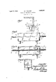
- Figure 1 represents a fragmentary. view of a building basement showing the water inlet pipe from the supply main and showing the device embodying the present invention coupled thereto;
- Figure 2 shows the device embodying the present invention in side elevation
- Figure 3 is a, vertical longitudinal sectional view through the present device
- the numeral 1 indicates a portion of a building foundation wall through whichthere passes the usual water pipe 2 which leads from a main water pipe or main (not shown) to the interior of building where it is coupled with the building water pipe line 3.
- the present water reducing device is indicated generally by the numeral 4 and as shown this consists of an elongated casing 5 which is here shown as of rectangularcross section, al-
- This receptacle or casing5 has a-removable cover 6 and one end is provided with an inlet opening 7 with which i connected a'nipple 8.
- Extending through the oppositewall of the casing is a pipe 9 which'extends forwardly to a point adjacent the forward end thereof through which the opening 7 is formed and terminates in bafiie plate '10 which extends completely across and is supported in thecasing as shown in Figure 4.
- the upper and lower edges of the baffle plate 10 terminate short of the top and bottom walls of the casing thus providing passages through which water may pass from the inlet opening 7 to the rear end of the casing.
- lhis pipe 9 passes through the baffle plate or wall 10 and is aligned with the opening 7.
- the bottom of the casing has secured thereto adjacent the forward end, an car 11 with which is pivotally attached a rod 12 which forms one of two members of a supporting element or pedestal which is indicated as a whole bythe numeral 13, theother member being indicated by the numeral 14.
- the member 14 is tubular to receive the rod 12 and the rod has threaded thereon a-nut-1-5-w-hich may be shifted for adjustment to any position and which rests upon the upper end of the tubular section 14 in the.- manner shown in Figure 1.
- the height of the casing-5 may be readily controlled.
- Aidj acent the rear end of the casing the bottom has a discharge pipe 16 connected there with through which water received by the casing-may be. carried off.
- the nipple 8 iscoupled by a suitable coupling sleeve117 with the inner end-of the inlet pipe 2 in the manner shown in Figure 1 so that the-water passing through the pipe 2 will discharge into "the casing 5 :againstthe baffle board or wall "and will then flow out through the pipe 16.
- The: plumber is thus I able to insert: the spiraldiexible'rod 18 into the pipei2, through ⁇ the pipe 9 as illustrated inl Figure 3 andefiect the removal ofrust or sediment from the pipe2 without himself becoming wetior having to receive the force of water escaping through the pipe 2aswould :be the'case if the present ldevice were not employed.
- a water pressurereducing device of the character described comprising a tubular body designed toreceive a pipe cleaning instrument, means constituting-a baffle plate for supporting an end ofsaid tubularbody in::a-lignment with a pipe into which said instrument is 'introduced,and means constituting a coupling between said baflie plate and said pipe.
- a water pressure reducing device of the character described comprising a hollow body, means for coupling an end of a water pipe with a wall of the body for discharge thercinto, an outlet for the body, a support in the body adjacent said wall, and a tube extending through a wall opposite said first wall and through said support and aligned with the said pipe coupling means for facilitating the extension of an instrument into a pipe connected with the said coupling means.
- a pressure reducing device of the character described comprising an elongated casing,-means for coupling a-pipe with one end wall or" said casing for discharge thereinto, an outlet for said casing, a tube extending. through the other end Wall of the casing and longitudinally therethrough to a point in proximity to the first end wall and aligned with the pipe coupling means, a baffle plate extending transversely of the casing adjacent the first wall and having said tube extending therethrough, and supporting means for the casing.
- a pressure reducing device of the character described comprising an elongated casing, means for coupling a pipe with one end wall of said casing for discharge thereinto, an outlet for said casing, a tube extendmg through the other end Wall of the casmg and longitudinally therethrough to a point in proximity to the first end wall and aligned with the pipe coupling means, a baifie plate extending transversely of the casing adjacent the first wall and having said tube extending therethrough, and vertically adjustable supporting means for the casmg;
- a pressure reducing device of the character described comprising a battle member, an elongated tubular body connected with and opening at one end through said baffie member, and means for holding said bal'lle member before the end of a pipe which is to be cleaned, with said body aligned with the pipe for the extension of a cleaning element through the body into the pipe.
Landscapes
- Engineering & Computer Science (AREA)
- Mechanical Engineering (AREA)
- Cleaning In General (AREA)
Description
" April 12, 1932. I B. F.- B-ENNER WATER PRESSURE REDUCING DEVICE Filed Oct. 1, 1931 Patented Apr. 12, 1932 gran STATES.
PATENT orF cE BENJAMIN F. BENNER, or PI-IILADELIHIA; PENNSYLVANIA WATER-PRESSURE REDUCING DEVICE Application filed October 1, 1931. Serial No. 566,331.
This invention relates to devices for the use of plumbers and pertains particularly to a device for reducing the pressure of water discharging from a pipe line, for the protection of the plumber while he is operating a cleaning device in the pipe.
In house plumbing systems it frequently becomes necessary to clean out the pipe line leading from the street main into the house Y and in doing this the plumber must operate a cleaning tool in the pipe against the pressure'of water escaping therefrom.
The primary object of the present invention is to provide a device which will operate to protect the plumber while cleaning out the pipe line, without in any manner interfering with the operation of the plpe cleaning tool.
supporting the casing in working position;
there is provided an outlet through the bottom through which the water is permitted to escape instead of discharging over the plumber as is the case when cleaning out inlet pipes without the benefit of a device of the character embodying the present invention. 7
The invention will be best understood from a consideration of the following detailed de scription taken in connection with the accompanying drawings forming part of this specification with the understanding, however, that the invention is not confined to any strict conformity with the showing. of the drawings but may be changed or modified so long as such changes or modifications mark no material departure from the salient features of the invention as expressed in the appended claims. v
In the drawings Figure 1 represents a fragmentary. view of a building basement showing the water inlet pipe from the supply main and showing the device embodying the present invention coupled thereto;
Figure 2 shows the device embodying the present invention in side elevation;
Figure 3 is a, vertical longitudinal sectional view through the present device;
Figure -4.--is a transverse sectional view taken on the line 4:4: of Figure 3.
Referring now more particularly to'the drawings wherein like numerals of reference indicate corresponding parts throughout the several views the numeral 1 indicates a portion of a building foundation wall through whichthere passes the usual water pipe 2 which leads from a main water pipe or main (not shown) to the interior of building where it is coupled with the building water pipe line 3.
The usual'elbow coupling between the inlet pipe 2 and the pipe 3 is not shown as this has been removed to show the application of the device embodying the present invention.
The present water reducing device is indicated generally by the numeral 4 and as shown this consists of an elongated casing 5 which is here shown as of rectangularcross section, al-
though it may be of any crosssectional design.
This receptacle or casing5 has a-removable cover 6 and one end is provided with an inlet opening 7 with which i connected a'nipple 8. Extending through the oppositewall of the casing is a pipe 9 which'extends forwardly to a point adjacent the forward end thereof through which the opening 7 is formed and terminates in bafiie plate '10 which extends completely across and is supported in thecasing as shown in Figure 4. The upper and lower edges of the baffle plate 10 terminate short of the top and bottom walls of the casing thus providing passages through which water may pass from the inlet opening 7 to the rear end of the casing. lhis pipe 9 passes through the baffle plate or wall 10 and is aligned with the opening 7.
The bottom of the casing has secured thereto adjacent the forward end, an car 11 with which is pivotally attached a rod 12 which forms one of two members of a supporting element or pedestal which is indicated as a whole bythe numeral 13, theother member being indicated by the numeral 14. The member 14: is tubular to receive the rod 12 and the rod has threaded thereon a-nut-1-5-w-hich may be shifted for adjustment to any position and which rests upon the upper end of the tubular section 14 in the.- manner shown in Figure 1.
It will thus beseen that the height of the casing-5 may be readily controlled.
Aidj acent the rear end of the casing the bottom has a discharge pipe 16 connected there with through which water received by the casing-may be. carried off.
In'the'use of the present water reducing device the nipple 8iscoupled by a suitable coupling sleeve117 with the inner end-of the inlet pipe 2 in the manner shown in Figure 1 so that the-water passing through the pipe 2 will discharge into "the casing 5 :againstthe baffle board or wall "and will then flow out through the pipe 16. The: plumber is thus I able to insert: the spiraldiexible'rod 18 into the pipei2, through\the pipe 9 as illustrated inl Figure 3 andefiect the removal ofrust or sediment from the pipe2 without himself becoming wetior having to receive the force of water escaping through the pipe 2aswould :be the'case if the present ldevice were not employed.
From: theforegoing it will be readily apiparent that'with aldevice of the character -2 iherein described the'cleaning of a water inlet pipe may be accomplished more: readily and with 1 less I unpleasantness for the workman than 'hastrheretofore been the case.
'Having thus described the invention, what I claimiis:
1. A pressure reducing device of: the character described comprisingahollow body :havingan inletand an outlet, means for coupling a pipe with said inlet, and means Within thecbody facilitating the extension of an. instrument through the inlet opening: into a-ipi'pe coupled therewith for effecting the cleaning of said pipe.
2. A water pressurereducing device of the character described, comprising a tubular body designed toreceive a pipe cleaning instrument, means constituting-a baffle plate for supporting an end ofsaid tubularbody in::a-lignment with a pipe into which said instrument is 'introduced,and means constituting a coupling between said baflie plate and said pipe.
3. A water pressure reducing device of the character described comprising a hollow body, means for coupling an end of a water pipe with a wall of the body for discharge thercinto, an outlet for the body, a support in the body adjacent said wall, and a tube extending through a wall opposite said first wall and through said support and aligned with the said pipe coupling means for facilitating the extension of an instrument into a pipe connected with the said coupling means.
A pressure reducing device of the character described comprising an elongated casing,-means for coupling a-pipe with one end wall or" said casing for discharge thereinto, an outlet for said casing, a tube extending. through the other end Wall of the casing and longitudinally therethrough to a point in proximity to the first end wall and aligned with the pipe coupling means, a baffle plate extending transversely of the casing adjacent the first wall and having said tube extending therethrough, and supporting means for the casing.
5. A pressure reducing device of the character described comprising an elongated casing, means for coupling a pipe with one end wall of said casing for discharge thereinto, an outlet for said casing, a tube extendmg through the other end Wall of the casmg and longitudinally therethrough to a point in proximity to the first end wall and aligned with the pipe coupling means, a baifie plate extending transversely of the casing adjacent the first wall and having said tube extending therethrough, and vertically adjustable supporting means for the casmg;
6. A pressure reducing device of the character described, comprising a battle member, an elongated tubular body connected with and opening at one end through said baffie member, and means for holding said bal'lle member before the end of a pipe which is to be cleaned, with said body aligned with the pipe for the extension of a cleaning element through the body into the pipe.
In testimony whereof I hereunto atfix my signature.
BENJAMIN F. B'ENNER.
Priority Applications (1)
| Application Number | Priority Date | Filing Date | Title |
|---|---|---|---|
| US566331A US1853597A (en) | 1931-10-01 | 1931-10-01 | Water-pressure reducing device |
Applications Claiming Priority (1)
| Application Number | Priority Date | Filing Date | Title |
|---|---|---|---|
| US566331A US1853597A (en) | 1931-10-01 | 1931-10-01 | Water-pressure reducing device |
Publications (1)
| Publication Number | Publication Date |
|---|---|
| US1853597A true US1853597A (en) | 1932-04-12 |
Family
ID=24262441
Family Applications (1)
| Application Number | Title | Priority Date | Filing Date |
|---|---|---|---|
| US566331A Expired - Lifetime US1853597A (en) | 1931-10-01 | 1931-10-01 | Water-pressure reducing device |
Country Status (1)
| Country | Link |
|---|---|
| US (1) | US1853597A (en) |
Cited By (1)
| Publication number | Priority date | Publication date | Assignee | Title |
|---|---|---|---|---|
| US2514339A (en) * | 1946-06-04 | 1950-07-04 | Pittsburgh Pipe Cleaner Compan | Pipe-cleaning seal |
-
1931
- 1931-10-01 US US566331A patent/US1853597A/en not_active Expired - Lifetime
Cited By (1)
| Publication number | Priority date | Publication date | Assignee | Title |
|---|---|---|---|---|
| US2514339A (en) * | 1946-06-04 | 1950-07-04 | Pittsburgh Pipe Cleaner Compan | Pipe-cleaning seal |
Similar Documents
| Publication | Publication Date | Title |
|---|---|---|
| US2366969A (en) | Flushing gun with convertible nozzle | |
| US1853597A (en) | Water-pressure reducing device | |
| US2147593A (en) | Device for removing scale, etc., from liquid containers | |
| US614749A (en) | Alexander pallas | |
| US3095001A (en) | Flushing device | |
| US1933165A (en) | Receptacle filling and emptying device | |
| US1796340A (en) | Waste-pipe cleaner | |
| US1923422A (en) | Device for controlling the wetness of steam | |
| WO2015194994A1 (en) | Device and method for protecting instruments for measuring the pressure and/or flow rate of wet gases | |
| US3616479A (en) | Plumber's nozzle | |
| US1774301A (en) | Air cleaner | |
| US3146952A (en) | Radiator cleaning device | |
| US2485008A (en) | Sewer flusher | |
| US875832A (en) | Cleaning attachment for feed-water pipes. | |
| US734682A (en) | Device for flushing drain-pipes. | |
| US1180960A (en) | Boiler-flue cleaner. | |
| US3072140A (en) | Blow-off fitting | |
| US1836101A (en) | Combination boiler tube blower | |
| US1808424A (en) | Steam purifying apparatus | |
| GB1579226A (en) | Surgical apparatus | |
| US729425A (en) | Boiler-cleaner. | |
| US2515460A (en) | Flow regulator for grease interceptors and the like | |
| US1113426A (en) | Suction apparatus. | |
| US3722008A (en) | Drain cleaners | |
| US2306445A (en) | High velocity sewer flusher |