US1853583A - Wheel and method of making the same - Google Patents
Wheel and method of making the same Download PDFInfo
- Publication number
- US1853583A US1853583A US328692A US32869228A US1853583A US 1853583 A US1853583 A US 1853583A US 328692 A US328692 A US 328692A US 32869228 A US32869228 A US 32869228A US 1853583 A US1853583 A US 1853583A
- Authority
- US
- United States
- Prior art keywords
- wheel
- spokes
- bushing
- hub
- rim
- Prior art date
- Legal status (The legal status is an assumption and is not a legal conclusion. Google has not performed a legal analysis and makes no representation as to the accuracy of the status listed.)
- Expired - Lifetime
Links
- 238000004519 manufacturing process Methods 0.000 title description 10
- 230000003014 reinforcing effect Effects 0.000 description 11
- 239000000463 material Substances 0.000 description 10
- 239000002184 metal Substances 0.000 description 4
- 238000000465 moulding Methods 0.000 description 3
- 238000005452 bending Methods 0.000 description 1
- 239000007859 condensation product Substances 0.000 description 1
- 238000010276 construction Methods 0.000 description 1
- 230000003203 everyday effect Effects 0.000 description 1
- 239000002657 fibrous material Substances 0.000 description 1
- 230000007246 mechanism Effects 0.000 description 1
- 238000000034 method Methods 0.000 description 1
- 238000012986 modification Methods 0.000 description 1
- 230000004048 modification Effects 0.000 description 1
- ISWSIDIOOBJBQZ-UHFFFAOYSA-N phenol group Chemical group C1(=CC=CC=C1)O ISWSIDIOOBJBQZ-UHFFFAOYSA-N 0.000 description 1
- 230000002787 reinforcement Effects 0.000 description 1
Images
Classifications
-
- B—PERFORMING OPERATIONS; TRANSPORTING
- B62—LAND VEHICLES FOR TRAVELLING OTHERWISE THAN ON RAILS
- B62D—MOTOR VEHICLES; TRAILERS
- B62D1/00—Steering controls, i.e. means for initiating a change of direction of the vehicle
- B62D1/02—Steering controls, i.e. means for initiating a change of direction of the vehicle vehicle-mounted
- B62D1/04—Hand wheels
-
- Y—GENERAL TAGGING OF NEW TECHNOLOGICAL DEVELOPMENTS; GENERAL TAGGING OF CROSS-SECTIONAL TECHNOLOGIES SPANNING OVER SEVERAL SECTIONS OF THE IPC; TECHNICAL SUBJECTS COVERED BY FORMER USPC CROSS-REFERENCE ART COLLECTIONS [XRACs] AND DIGESTS
- Y10—TECHNICAL SUBJECTS COVERED BY FORMER USPC
- Y10T—TECHNICAL SUBJECTS COVERED BY FORMER US CLASSIFICATION
- Y10T29/00—Metal working
- Y10T29/49—Method of mechanical manufacture
- Y10T29/49481—Wheel making
- Y10T29/49488—Steering wheel
-
- Y—GENERAL TAGGING OF NEW TECHNOLOGICAL DEVELOPMENTS; GENERAL TAGGING OF CROSS-SECTIONAL TECHNOLOGIES SPANNING OVER SEVERAL SECTIONS OF THE IPC; TECHNICAL SUBJECTS COVERED BY FORMER USPC CROSS-REFERENCE ART COLLECTIONS [XRACs] AND DIGESTS
- Y10—TECHNICAL SUBJECTS COVERED BY FORMER USPC
- Y10T—TECHNICAL SUBJECTS COVERED BY FORMER US CLASSIFICATION
- Y10T74/00—Machine element or mechanism
- Y10T74/20—Control lever and linkage systems
- Y10T74/20576—Elements
- Y10T74/20732—Handles
- Y10T74/20834—Hand wheels
Definitions
- the present invention relates to wheels and their manufacture and has for an object the provision of a molded wheel which will be strong, rigid, durable, comfortable to the hand and one which may be economically and expeditiously manufactured.
- a molded wheel which will be strong, rigid, durable, comfortable to the hand and one which may be economically and expeditiously manufactured.
- the invention concerns the manufacture of integrally molded wheels provided with reinforcement for the various portions therell of. I have found that a wheel of proper strength, neatness and other desired qualities maybe successfully made of very inexpensive materials and at a correspondingly low cost for labor if the elements going to make up the wheel are judiciously designed and selected.
- a wheel composed of a rim, spokes and a hub may be made principally of various moldable materials and reinforced by skeleton members which 35 before molding are merely assembled loosely with each other.' This permits the use of parts which require no special operations in their manufacture but which on the other hand may be chosen from articles of everyday use made in large quantities and at a price which may be only a half or a third of the price which would be incurred if all parts and materials had to be especially made and prepared.
- the wheel illustrated is cupped on the upper side at the center for the reception of mechanisms or arts associated with the wheel.
- this cupped opening is disposed at the inner ends of the spokes and i a hub extension is formed on the lower side of the spokes to take the bushing employed for attaching the wheel to a torque shaft.
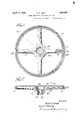
- igure 1 is a top plan view of the finished wheel
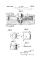
- Figure 2 is an axial section taken on the line 22 of Figure 1;
- Figure 3 is a view similarto Figure 2 but showing the parts as they would appear in a mold prior to being molded;
- FIGS. 4 and 5 are detail views of a bushing
- Figures6 and 7 are detail views of a collar employed.
- the finished wheel comprises a rim 10, spokes 20, and a hub 30, the hub including a body portion 31 embracing the inner ends of the spokes and an extension 32 axially offset with respect to the inner ends of the spokes.
- the extension 32 is provided with a bushing 35, preferably of metal, for securing the wheel to a shaft,- for. example, the steering shaft of an automobile.
- the wheel On its upper side the wheel is formed with an enlarged bore or recess 33 for the rece tion of parts appurtenant to the wheel. s illustrated, the bore 33 extends into the hub approximately to the lower edge of the spokes. There may also be an enlarged bore 36 formed in the hub extension 32 below the bushing 35 for the reception of other appurtenant parts, such for example, as the upper end of a tube or steering column surrounding the steering shaft.
- a metal reinforcing member 21 extends throughout the length of each spoke, being 100 hers 21.
- the members 21 may pass through the'band and have their heads 23 engaged behind the outer side of the band.
- the member 21 Nearer its inner end the member 21 is provided with a more sharply bent portion 2-1 adapted to lie along the wall of the bushing and brace the arms thereupon.
- a collar 37 fits closely about but slidably upon the bushing 35 and is provided with notches 38 adapted to fit'over the ribs 35a formed on the exterior surface of the bushing. If desired the bushing may be formed with a flange 40 on its upper end to hold the collar in proper positon when the molding.
- the collar 37 is enlarged in the region of the spokes as at 39 to receive the shanks of the spoke reinforcing members and hold them in toward the bushing. As shown, the enlargements 39 are made at the same places in the collar asthe notches 38 thereby forming enlarged openings at several places.
- one method of making the wheel may be as follows:
- the moldable material for the low- ,er portion of the wheel may be ⁇ laid loosely in the mold or maybe blanked out and then laid in the mold.
- the reinforcing members which have previously been loosely assembled by threading the members 21 inward through holes in the rim ring 11 and passing the bent ends 24 through the collar 37 which has been slipped on the'bushing 35, are next placed in position after which the remainder of the moldable material is placed in the mold, which is closed under-high pressure. If desired separate partially formed blanks for the rim, spokes and hub may be used.
- moldable material may be used. I have obtained good results with paper or other fibrous material impregnated or coated with a suitable phenolic condensation product. When such material is used heat as well as pressure is applied to the mold. For most moldable materials, in fact, both heat and high pressure will be employed.
- Such a wheel is braced to withstand severe strains either torsional, radial, or axial and especially will the wheel withstand heavy downward pres-' sures upon its rimdue to the vertical bracingof the spoke reinforcing members against the hub bushing.
- a reinforcing wheel made according to this invention is particularl desirable in case of accidents since it Wlll not readily break or pull apart but instead all of the parts will be held together even though the molded material may, on account of unusual severe'stress, be fractured.
- the spokes will not separate from the'hub due to the fact that the spoke reinforcing rod is engaged with parts connected to the hub bushing and the rim will not separate from the spokes due to the fact that the head ofthe reinforcing rod in the spokes is engaged behind the outer surface of the ring disposed in the rim.
- said hub being formed with a hub extension axially ofiset with respect to the inner ends of the spokes and a central bore including a counterborein the region of the'inner ends of the spokes, a bushing in the hub extension, a flange on the end of the bushing adjacent the spokes, longitudinal splines on the outer surface of said bushing, a collar fitting over said bushing below the flange thereof and provided with apertures corresponding in number and position to said spokes, an apertured metal ring in said rim, and metal reinforcing rods extending through said ring and spokes from the rim into the hub extension, said rods having an enlargement enga-gin the outer. side of said ring and a bent portion at the other end entering the apertures of the collar and braced against the splines of the bushing.
Landscapes
- Engineering & Computer Science (AREA)
- Chemical & Material Sciences (AREA)
- Combustion & Propulsion (AREA)
- Transportation (AREA)
- Mechanical Engineering (AREA)
- Steering Controls (AREA)
Description
April 12, 1932. G SMITH WHEEL AND METHOD OF MAKING THE SAME Filed Dec. 27, 1928 2 Sheets-Sheet 1 gnoembo'c @om/ 507% I 33 /7 Qbtomuf April 12, 1932.
G. E. SMITH WHEEL AND METHOD OF MAKING THE SAME 2 Sheets-Sheet 2 FiledDeG. 27, 1928 Qnowntoz Patented Apr. 12, 1932 UNITED. STATES PATENT OFFICE GRANT E. SMITH, OF POUGHKEEPSIE, NEW YORK, ASSIGNOR TOIPOUVAILSIITH GOR- PORATION, OF ROUGHKEEIPSIE, NEW YORK, A CORPORATION OF NEW YORK WHEEL AND METHOD OF MAKING THE SAME Application filed December 27, 1928. Serial No. 328,692.
The present invention relates to wheels and their manufacture and has for an object the provision of a molded wheel which will be strong, rigid, durable, comfortable to the hand and one which may be economically and expeditiously manufactured. Inasmuch as the invention has been developed in connection with the manufacture of steering wheels for automobiles, such an embodiment has been selected for illustration and description herein.
The invention concerns the manufacture of integrally molded wheels provided with reinforcement for the various portions therell of. I have found that a wheel of proper strength, neatness and other desired qualities maybe successfully made of very inexpensive materials and at a correspondingly low cost for labor if the elements going to make up the wheel are judiciously designed and selected. For example, a wheel composed of a rim, spokes and a hub may be made principally of various moldable materials and reinforced by skeleton members which 35 before molding are merely assembled loosely with each other.' This permits the use of parts which require no special operations in their manufacture but which on the other hand may be chosen from articles of everyday use made in large quantities and at a price which may be only a half or a third of the price which would be incurred if all parts and materials had to be especially made and prepared.
In order to furnish the wheelwith the desired strength and rigidity with the optimum size and outline I have found it expedient to include in the wheel certain reinforcing elements such as a bushing in the hub, rods in the spokes, and a ring in the rim. These elements are suitably associated or connected in the finished wheel so as to provide good connections between the several parts of the wheel as well as to serve as skeleton or base members to strengthen these parts in themselves.
The wheel illustrated is cupped on the upper side at the center for the reception of mechanisms or arts associated with the wheel. Preferab y this cupped opening is disposed at the inner ends of the spokes and i a hub extension is formed on the lower side of the spokes to take the bushing employed for attaching the wheel to a torque shaft.
With this construction there is a somewhat weakened portion which connects the spokes to the hub extension. The reinforcing elementsherein provided materially strengthen this section and by their shape and disposition transmit stralns from the spokes directly to the hub bushing.
The enumerated and further objects of the invention will be best understood from the description of the illustrative embodiment thereof shown in the accompanying draw- -in s, in which:
igure 1 is a top plan view of the finished wheel;
Figure 2 is an axial section taken on the line 22 of Figure 1;
Figure 3 is a view similarto Figure 2 but showing the parts as they would appear in a mold prior to being molded;
Figures 4 and 5 are detail views of a bushing; and
Figures6 and 7 are detail views of a collar employed.
The finished wheel,as shown in Figures 1 and 2 comprises a rim 10, spokes 20, and a hub 30, the hub including a body portion 31 embracing the inner ends of the spokes and an extension 32 axially offset with respect to the inner ends of the spokes. The extension 32 is provided with a bushing 35, preferably of metal, for securing the wheel to a shaft,- for. example, the steering shaft of an automobile.
.On its upper side the wheel is formed with an enlarged bore or recess 33 for the rece tion of parts appurtenant to the wheel. s illustrated, the bore 33 extends into the hub approximately to the lower edge of the spokes. There may also be an enlarged bore 36 formed in the hub extension 32 below the bushing 35 for the reception of other appurtenant parts, such for example, as the upper end of a tube or steering column surrounding the steering shaft.
A metal reinforcing member 21 extends throughout the length of each spoke, being 100 hers 21. For example, the members 21 may pass through the'band and have their heads 23 engaged behind the outer side of the band.
Toward its inner end the reinforcing member 21 is bent down from the line of the spoke so as to enter the hub extension. This bending commences at the point a (Figure 2) and as maybe observed by comparing Figures 2 and 3 is principally imparted by the compressing operation through the action of the plunger 52 employed to form the recess or enlarged bore 33.
Nearer its inner end the member 21 is provided with a more sharply bent portion 2-1 adapted to lie along the wall of the bushing and brace the arms thereupon. A collar 37 fits closely about but slidably upon the bushing 35 and is provided with notches 38 adapted to fit'over the ribs 35a formed on the exterior surface of the bushing. If desired the bushing may be formed with a flange 40 on its upper end to hold the collar in proper positon when the molding.
The collar 37 is enlarged in the region of the spokes as at 39 to receive the shanks of the spoke reinforcing members and hold them in toward the bushing. As shown, the enlargements 39 are made at the same places in the collar asthe notches 38 thereby forming enlarged openings at several places.
Referring to Figure 3 which shows the various portions of the wheel before molding, one method of making the wheel may be as follows: The moldable material for the low- ,er portion of the wheel may be {laid loosely in the mold or maybe blanked out and then laid in the mold. The reinforcing members, which have previously been loosely assembled by threading the members 21 inward through holes in the rim ring 11 and passing the bent ends 24 through the collar 37 which has been slipped on the'bushing 35, are next placed in position after which the remainder of the moldable material is placed in the mold, which is closed under-high pressure. If desired separate partially formed blanks for the rim, spokes and hub may be used.
Various kinds of moldable material may be used. I have obtained good results with paper or other fibrous material impregnated or coated with a suitable phenolic condensation product. When such material is used heat as well as pressure is applied to the mold. For most moldable materials, in fact, both heat and high pressure will be employed.
parts are assembled for I The described assembly and method permit theuse of simple parts and inexpensive materials in the wheel; provide rapid assembly; and when completed, a wheel whlch" 'issmooth to the hand, of neat appearance,
and rigid and strong as a unit. Such a wheel is braced to withstand severe strains either torsional, radial, or axial and especially will the wheel withstand heavy downward pres-' sures upon its rimdue to the vertical bracingof the spoke reinforcing members against the hub bushing.
A reinforcing wheel made according to this invention is particularl desirable in case of accidents since it Wlll not readily break or pull apart but instead all of the parts will be held together even though the molded material may, on account of unusual severe'stress, be fractured. The spokes will not separate from the'hub due to the fact that the spoke reinforcing rod is engaged with parts connected to the hub bushing and the rim will not separate from the spokes due to the fact that the head ofthe reinforcing rod in the spokes is engaged behind the outer surface of the ring disposed in the rim.
It will be apparent that various changes and modifications may be made both in structur'eand methodof manufacture of the wheel, the specific description being given solely for purposes of illustration.
What I claim isi A steering wheel comprising a molded rim,
hub and spokes, said hub being formed with a hub extension axially ofiset with respect to the inner ends of the spokes and a central bore including a counterborein the region of the'inner ends of the spokes, a bushing in the hub extension, a flange on the end of the bushing adjacent the spokes, longitudinal splines on the outer surface of said bushing, a collar fitting over said bushing below the flange thereof and provided with apertures corresponding in number and position to said spokes, an apertured metal ring in said rim, and metal reinforcing rods extending through said ring and spokes from the rim into the hub extension, said rods having an enlargement enga-gin the outer. side of said ring and a bent portion at the other end entering the apertures of the collar and braced against the splines of the bushing.
In testimony whereof I have signed my name to this specification this14th day of December, 1928. v
, GRANT E. SMITH.
Priority Applications (1)
| Application Number | Priority Date | Filing Date | Title |
|---|---|---|---|
| US328692A US1853583A (en) | 1928-12-27 | 1928-12-27 | Wheel and method of making the same |
Applications Claiming Priority (1)
| Application Number | Priority Date | Filing Date | Title |
|---|---|---|---|
| US328692A US1853583A (en) | 1928-12-27 | 1928-12-27 | Wheel and method of making the same |
Publications (1)
| Publication Number | Publication Date |
|---|---|
| US1853583A true US1853583A (en) | 1932-04-12 |
Family
ID=23282016
Family Applications (1)
| Application Number | Title | Priority Date | Filing Date |
|---|---|---|---|
| US328692A Expired - Lifetime US1853583A (en) | 1928-12-27 | 1928-12-27 | Wheel and method of making the same |
Country Status (1)
| Country | Link |
|---|---|
| US (1) | US1853583A (en) |
Cited By (4)
| Publication number | Priority date | Publication date | Assignee | Title |
|---|---|---|---|---|
| DE1087022B (en) * | 1958-07-28 | 1960-08-11 | Leopold Schmid | Steering wheel with low-lying hub for motor vehicles |
| US4313249A (en) * | 1978-03-23 | 1982-02-02 | Ford Motor Company | Method of manufacturing components adapted to be mounted on a shaft |
| US4811472A (en) * | 1985-04-26 | 1989-03-14 | Toyoda Gosei Co., Ltd. | Method of making a steering wheel |
| US5136895A (en) * | 1990-07-03 | 1992-08-11 | Ecia | Steering wheel frame for an automobile vehicle or the like |
-
1928
- 1928-12-27 US US328692A patent/US1853583A/en not_active Expired - Lifetime
Cited By (4)
| Publication number | Priority date | Publication date | Assignee | Title |
|---|---|---|---|---|
| DE1087022B (en) * | 1958-07-28 | 1960-08-11 | Leopold Schmid | Steering wheel with low-lying hub for motor vehicles |
| US4313249A (en) * | 1978-03-23 | 1982-02-02 | Ford Motor Company | Method of manufacturing components adapted to be mounted on a shaft |
| US4811472A (en) * | 1985-04-26 | 1989-03-14 | Toyoda Gosei Co., Ltd. | Method of making a steering wheel |
| US5136895A (en) * | 1990-07-03 | 1992-08-11 | Ecia | Steering wheel frame for an automobile vehicle or the like |
Similar Documents
| Publication | Publication Date | Title |
|---|---|---|
| US1853583A (en) | Wheel and method of making the same | |
| US2041739A (en) | Steering wheel | |
| DE102007041091A1 (en) | Bicycle wheel rim has annular walls extending from pair of lateral walls of outer metal portion, which includes thick central portion and lateral edge portion arranged along lateral direction of central portion | |
| US4976801A (en) | Process for manufacturing a steering wheel for a motor vehicle | |
| EP0814010B1 (en) | Sheet metal steering wheel | |
| US1943915A (en) | Steering wheel | |
| DE633369C (en) | Metal wagon wheel | |
| US1785897A (en) | One-piece rim and spider steering wheel | |
| DE20101868U1 (en) | Vehicle steering wheel | |
| US2187604A (en) | Automobile steering wheel construction | |
| US2236674A (en) | Steering wheel hub | |
| US1816445A (en) | Steering wheel and method of making the same | |
| US1784733A (en) | Steering wheel | |
| US1854780A (en) | Steering wheel | |
| DE10330095A1 (en) | Tire / wheel assembly, run-flat support member and manufacturing method therefor | |
| US1843676A (en) | Steering wheel | |
| US2148559A (en) | Steering wheel construction | |
| US1847758A (en) | Steering wheel | |
| US2071280A (en) | Method of making vehicle wheels | |
| EP3548361B1 (en) | Steering wheel core for a vehicle and a steering wheel with such a core | |
| US1662238A (en) | Spool or bobbin | |
| US1869099A (en) | Steering wheel | |
| US1825393A (en) | Steering wheel | |
| US2304945A (en) | Steering wheel insert | |
| US1713035A (en) | Handwheel |