US1853581A - Method and apparatus for scavenging core drills - Google Patents
Method and apparatus for scavenging core drills Download PDFInfo
- Publication number
- US1853581A US1853581A US453227A US45322730A US1853581A US 1853581 A US1853581 A US 1853581A US 453227 A US453227 A US 453227A US 45322730 A US45322730 A US 45322730A US 1853581 A US1853581 A US 1853581A
- Authority
- US
- United States
- Prior art keywords
- core
- barrel
- drill
- plunger
- plate member
- Prior art date
- Legal status (The legal status is an assumption and is not a legal conclusion. Google has not performed a legal analysis and makes no representation as to the accuracy of the status listed.)
- Expired - Lifetime
Links
Images
Classifications
-
- E—FIXED CONSTRUCTIONS
- E21—EARTH DRILLING; MINING
- E21B—EARTH DRILLING, e.g. DEEP DRILLING; OBTAINING OIL, GAS, WATER, SOLUBLE OR MELTABLE MATERIALS OR A SLURRY OF MINERALS FROM WELLS
- E21B25/00—Apparatus for obtaining or removing undisturbed cores, e.g. core barrels, core extractors
Definitions
- core drills of the usual construction consist of a core receiving barrel having mounted on its lower end a cutter head and provided at its upper end with means for attaching same to a string of drill pipe.
- the core receiving barrel may be a separate element enclosed within an outer barrel about which circulating fluid is adapted to be delivered to the cutting head, in which case it is known as a double core drill; or it may be a single barrel provided with a cutter head, in which case it is known as a single core drill.
- the upper end of the core receiving barrel is provided with a valve adapted to direct the circulating fluid away from the core receiving chamber.
- the primary object of this invention to produce a core drill in which the usual valve mentioned above is l eliminated, and in which all of the mud or cavings that accumulate in the core receiving barrel during the process of lowering the drill into the well, may be scavenged therefrom prior to initiating thedrillin operation.
- the plunger referred to above is so constructed that excessive gas pressure building up in the receiving barrel above the core may be released into the drill string.
- Fig. 2 is an enlarged sectional elevation showing a preferred form of plunger or packer contemplated by our invention
- Fig. 4 is a sectional elevation showing the
- the plunger or piston was constructed so as to permit the release of excessive gas pressures above the core.
- the gas tends to accumulate above the core and in some instances its pressure is sufficient to greatly retard the coring action.
- the cap 31 With the purpose of releasing such pressure we provide the cap 31 with a cut-away periphery as indicated at 31', which permits the partial collapse of the packer 30 when the gas pressure in the core barrel exceeds the fluid pressure in the drill string.
- This construction has a further advantage in that it permits the egress of such liquid as may accumulate in the barrel between the core and the bottom plunger stop when the coring operation is initiated.
- the plunger 25a is the lsame as the plunger described in connection with Figures 1 and 2.
- the core barrel shown in this form of our invention is, however, of the single barrel type and is shown as comprising a core receiving barrel 40 provided with cutting teeth 41 at its lower end and having a head 42 at its upper end whereby it may be attached to a.drill string 43.
- the head member 42 is provided with fluid circulating passages 44 through which the circulating fluid is delivered into the well at the upper end of the core barrel.
- the device contemplated by our invention has a further desirable feature in the eX- tracting of. the core from thebarrel. It is the usual practice to employ either a mechani-l cally or hydraulically operated Vplunger which is inserted through the upper end of the core barrel after the valve cage and its associated parts have been removed. In the useof our 'invention the onlyoperations necessary to gemove the core fromthe barrel are the rermovalfof the cutter head and, of course, the removal of the barrel'from the drill string, an adaptor may be placed over the core receiving barrel and hydraulic pressure applied to the upper end of the plungi'er, such vpressure being 'effective to force the core from thevcore barrel. y
- a core drillembodying a core receiv-V ing barrel, and a piston slidably mounted therein, said piston having rotatably ucom nected sections.
- a core drill embodying: a core receiving barrel, and a piston slidably mounted therein, said piston comprising a packing member and a core engaging member rotatably attached to said packing member.
- a core drill adapted tobe attached to a drill string and to receive a circulating fluid, said core drill embodying: an unobstructed core receiving barrel; and a piston slidably mounted in said core receiving barrel, said core .drill being provided with fluid outlet openings of such size that the pressure of the circulating fluid is effective to force said piston downwardly through said core barrel prior to the engagement of said drillA with the formation.
- a core drill adapted to be attached toa .drill string and to receive a circulating fluid, said core drill embodying: a core receiving barrel 'having an unobstructed opening in its upper end portion; and a piston slidably A.mounted in said core barrel, said piston being adapted for movement downwardly through said inner barrel by the pressure of circulating fluid admitted through said unobstructed opening.
- a core drill the combination of a core barrel and a piston slidably mounted vtherein, said piston comprising: a plate member;v a packing member' mounted on the upper end of said plate member; and a core engaging member rotatably mounted on the bottom ot' said plate member.
- a core drill the combination of a core barrel and a piston slidably mounted therein, said piston comprising: a plate member; a packing member mounted on the upper end of said plate member; a protecting cap mounted above said packing member and secured to said plate member; and a core engaging niember rotatably mounted on the bottom of said plate member.
- the method of scavenging a core drill which includes forcing a packing member downwardly through the core receiving barrel in said drill by means of circulating fluid prior to the engagement of the core drill with the formation.
Description
April 12, 1932- J. M. scHMlssRAUTER ET AL 1,853,581
METHOD AND APPARATUS FOR SCAVENGING CORE DRILLS Filed May 17, 1930 Patented Apr. 12, 1932 UNITED STATES PATENT OFFICE JOHN M. SCHMISSRAUTER, OF SAN PEDRO, AND JAMES E. HARRIS,V OF LOMITA. CALIFORNIA METHOD AND APPARATUS FOR SCAYENGING COBEDBILLS Application filed May 17, .1930. Serial No. 453,227.
This invent-ion has to do in a general way with the art of obtaining samples of formation in oil drilling operations through the use of core drills, and is more particularly related to an improvement in the construction of core drills designed to eliminatethe valve or valves therein and their attendant undesirable features.
It is well known to those familiar with the art that core drills of the usual construction consist of a core receiving barrel having mounted on its lower end a cutter head and provided at its upper end with means for attaching same to a string of drill pipe. The core receiving barrel may be a separate element enclosed within an outer barrel about which circulating fluid is adapted to be delivered to the cutting head, in which case it is known as a double core drill; or it may be a single barrel provided with a cutter head, in which case it is known as a single core drill. In either event the upper end of the core receiving barrel is provided with a valve adapted to direct the circulating fluid away from the core receiving chamber. In the case of a single barrel core drill the circulating fluid may be directed into the well at the top of the core barrel, or it may be carried downwardly to the cutter head through a passage or a plurality of passages provided in the wall of the barrel. In the use of core drills of this character there is always a tendency for the mud and cavings at the bottom of the well to accumulate in the core receiving barrel and in some cases these cavings stick in the valve and pack in the core barrel, greatly reducing the possible recovery during the cormg operation.
It is always necessary, in extracting the core from the barrel, to remove the valve and the valve cage, and since these members frequently become stuck and corrode', this operation sometimes requires considerable tlme. It is, therefore, a further object of this invention to produce a device of the class described whcrein the core may be extracted without necessitating the removal of a valve cage or similar part, and in which means are contained within the core barrel for forcing the core therefrom.
In view of the fact that abrasive material is continually passing through the valve cage, the valve and the cage in core barrels yare readily worn awa and must be frequently replaced. It is, t erefore, the primary object of this invention to produce a core drill in which the usual valve mentioned above is l eliminated, and in which all of the mud or cavings that accumulate in the core receiving barrel during the process of lowering the drill into the well, may be scavenged therefrom prior to initiating thedrillin operation. These objects are accomplished y making the core receiving barrel so that it is substantially unobstructed throughout its length, and providing same with a plunger that s i ably engages the interior of the core receiving barrel and is adapted for longitudinal movement therein.
It is a further object of this invention to produce a plunger for the use described above, which is of novel character in that it consists of a packing section and a core engaging section rotatably attached to the packin section. By constructing the plunger in thls manner the core barrel is permitted t0 rotate with respect to the core without imparting any twisting or shearing action to the core due to its engagement with the plunger.
It is a further object of this invention to provide a core barrel of the class described, with a stop ferrule, the external diameter of which may be chosen so as to form a restricted passage for the circulating fluid, that will bring about a differential pressure upon the head of the plunger, forcing the same downwardly through the core barrel prior to the engagement of the cutting head with the formation.
It is a noteworthy feature of the device contemplated by our invention, that the plunger referred to above is so constructed that excessive gas pressure building up in the receiving barrel above the core may be released into the drill string.
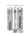
The details in the construction of certain preferred embodiments of our invention, together with other objects attending its production, will be best understood from the following description of the accompanying drawings which are chosen for illustrative purposes only, and in which Fig. 1 is a sectional elevation showing the lower end of the bore hole having a core drill equipped with an embodiment of our invention suspended therein;
Fig. 2 is an enlarged sectional elevation showing a preferred form of plunger or packer contemplated by our invention;
Fig. 3 is a sectional elevation showing the manner in which our invention may be-adapted to use in a single barrel core drill;
Fig. 4 is a sectional elevation showing the |manner in which our invention may be adapted to another form of single barrel core drill.
iMore particularly describing the invention as herein illustrated, reference numeral 11 indicates a core drill comprising an outer barrel 12 and an inner barrel 13. A cutting head 14 of any well known type is shown as being mounted upon the lower end portion of the outer barrel 12, and the inner barrel 13 is shown as being secured within the throat of the cutter head in the usual manner. The cutter head 14 is provided with core catchers 16 adapted to break and retain the core in the usual manner, and is also provided' with circulating passages 17 through which the circulating fluid is delivered to the cutting blades 18 from the space between the inner and outer barrels. The upper end portion of the outer barrel is provided with the usual type of adaptor 20 whereby the drill may be suspended from the lower end of a drill string 21. The upper end portion of the inner barrel 13 is adapted to receive a ferrule 23 which may be made of an external diameter such that the fluid passage between the drill string and the space defined by the inner and outer barrels is restricted so as to effect a differential pressure on the circulating fluid Within the inner barrel prior to the engagement of the cutter head with the formation. This ferrule also acts as av stop to limit the upward movement of the plunger.
As mentioned in the fore part of the specification, the essence oi this invention resides in the provision of a` packing inember or plunger within theinner barrel and may be broadly considered as a method of scavenging the inner barrel by constructing the same so that its upper end is unobstructed, and, providing same with a packin member that may be forced downwardly t erethrough by the differential pressure created, in the manner mentioned above. The packing member or plunger is generally indicated in the drawings by reference numeral 25, and is shown as consisting of a central plate member 26 which has a downwardly extending projection 27 adapted to support a rotatable core engaging member 28. In order that the frictional resistance between the core engaging member 28 and the plate member 26 may be reduced to a minimum, we prefer to interpose a series of ball bearings 27 between these two members. Reference numeral 30 indicates a rubber packing which is mounted upon the upper end portion of the plate member 26, such packing being shown as interposed between a flanged retaining cap 31 and the plate member 26. The retaining cap 31 not only holds the packing 30 in position, but it also provides a metallic protection for the packer which is adapted to engage the stop in the upper end portion of the barrel. Reference numeral 32 indicates a bolt or pin which is used to force the packing member 30 into pressure engagement with the plate member 26. The rotatable core engaging member 28 is shown as being provided with a downwardly extending annular flange 34 which is adapted to assist in aligning the upper end of the core within the core receiving barrel.
It was pointed out as a feature of this invention, that the plunger or piston was constructed so as to permit the release of excessive gas pressures above the core. When drills of this character are operating in formations of high gas pressure the gas tends to accumulate above the core and in some instances its pressure is sufficient to greatly retard the coring action. For the purpose of releasing such pressure we provide the cap 31 with a cut-away periphery as indicated at 31', which permits the partial collapse of the packer 30 when the gas pressure in the core barrel exceeds the fluid pressure in the drill string. This construction has a further advantage in that it permits the egress of such liquid as may accumulate in the barrel between the core and the bottom plunger stop when the coring operation is initiated.
In the operation of this device the core drill is lowered into the well to a point which is located a slight distance abovethe bottom of the well. The pump is then started, placing a considerable pressure upon the circulating fluid and the restricted passages through which the circulating fluid is delivered to the cutter head are effective to bring about a differential pressure upon the plunger member 25 which is sufficient to force the same downwardly into engagement with the core catcher or any other suitable stopprovided in the receiving barrel. The movement of the plungerl member downwardly through the barrel removes all of the cavings and mud from the barrel, leaving a clean passage for the core as it advances upwardly in the barrel` movin" the plunger therewith.
It will be understood by those familiar with the art that the resistance offered to the core by circulating fluid is substantially the same as it would bc if the upper end of the inner barrel were provided with a valve, since the valve must always operate against the circulating fluid in the same manner as the plunger 25.
In that form of our invention shown in Fig. 3, the plunger 25a is the lsame as the plunger described in connection with Figures 1 and 2. The core barrel shown in this form of our invention is, however, of the single barrel type and is shown as comprising a core receiving barrel 40 provided with cutting teeth 41 at its lower end and having a head 42 at its upper end whereby it may be attached to a.drill string 43. The head member 42 is provided with fluid circulating passages 44 through which the circulating fluid is delivered into the well at the upper end of the core barrel.`I
In ithe form of ourinvention sho'wn in Fig. 4, the plunger 25?) is the same as the plunger 25 shown in Figs. 1 and 2 Aand the core drill shown is 0fthe single barrel type, consisting of a barrel 45 having a cutting head 46 mounted on its lower end and provided with a head 47 whereby ift is, attached to a drill string 48. In this form of core drill the cir culating fluid is delivered tothe cutter head through a plurality of longitudinally eX- tending passages 49 which are provided in the wallof the core barrel.
In both of these last described forms of our invention the passages 44 and 49 are into engagement with` the core catcher prior` to the initiation of a coring operation, and Fig, 4 shows the plunger as having been `forced into the top of the barrel by a core 50.
The device contemplated by our invention has a further desirable feature in the eX- tracting of. the core from thebarrel. It is the usual practice to employ either a mechani-l cally or hydraulically operated Vplunger which is inserted through the upper end of the core barrel after the valve cage and its associated parts have been removed. In the useof our 'invention the onlyoperations necessary to gemove the core fromthe barrel are the rermovalfof the cutter head and, of course, the removal of the barrel'from the drill string, an adaptor may be placed over the core receiving barrel and hydraulic pressure applied to the upper end of the plungi'er, such vpressure being 'effective to force the core from thevcore barrel. y
It will be understood thatwhile w,e have herein. 'described and illustrated one preerred form of our invention and suggested various applications thereof,- the invention is not limited to the precise .construction described above, but includes within its scope -whatever changes fairly come within the spirit'of the appended claims.' 7e claim as our/invention:
1. A core drillembodying: a core receiv-V ing barrel, and a piston slidably mounted therein, said piston having rotatably ucom nected sections.
2. A core drill embodying: a core receiving barrel, and a piston slidably mounted therein, said piston comprising a packing member and a core engaging member rotatably attached to said packing member.
3. A core drill adapted tobe attached to a drill string and to receive a circulating fluid, said core drill embodying: an unobstructed core receiving barrel; and a piston slidably mounted in said core receiving barrel, said core .drill being provided with fluid outlet openings of such size that the pressure of the circulating fluid is effective to force said piston downwardly through said core barrel prior to the engagement of said drillA with the formation. l
4. A core drill adapted to be attached toa .drill string and to receive a circulating fluid, said core drill embodying: a core receiving barrel 'having an unobstructed opening in its upper end portion; and a piston slidably A.mounted in said core barrel, said piston being adapted for movement downwardly through said inner barrel by the pressure of circulating fluid admitted through said unobstructed opening.
5. In a core drill, the combination of a core barrel and a piston slidably mounted vtherein, said piston comprising: a plate member;v a packing member' mounted on the upper end of said plate member; and a core engaging member rotatably mounted on the bottom ot' said plate member.
6. In a core drill, the combination of a core barrel and a piston slidably mounted therein, said piston comprising: a plate member; a packing member mounted on the upper end of said plate member; a protecting cap mounted above said packing member and secured to said plate member; and a core engaging niember rotatably mounted on the bottom of said plate member.
7.' In a core drill, the combination of a core barrel and a piston slidably mounted therein, said piston comprising: a plate member; a packing member mounted on the upper end of said plate member; av protecting cap mounted above said packing member and secured to said plate member, said protecting cap having adownwardly extending portion which extends into said packer; and a core engaging member rotatably mounted on the bottomvof said plate member.
8. In a core drill, the combination of a core barrel and a piston slidably mounted tlierein,`said piston comprising: a pla-te member; a packing member mounted on the upper end of said plate member; a protecting cap mounted above said packing member and secured to said plate member, said protecting pression of said packing member relative thereto; and a core engaging member rotatably mounted 4on the bottom of said pla-te member.
9.` The method of scavenging a core drill, which includes forcing a packing member downwardly through the core receiving barrel in said drill by means of circulating fluid.
10. The method of scavenging a core drill, which includes forcing a packing member downwardly through the core receiving barrel in said drill by means of circulating fluid prior to the engagement of the core drill with the formation.
In testimony whereof, we have hereunto set our hands at Los Angeles, California, this 7th day of May, 1930.
JOHN `M. SCHMISSRAUTER. JAMES E. HARRIS.
Priority Applications (1)
| Application Number | Priority Date | Filing Date | Title |
|---|---|---|---|
| US453227A US1853581A (en) | 1930-05-17 | 1930-05-17 | Method and apparatus for scavenging core drills |
Applications Claiming Priority (1)
| Application Number | Priority Date | Filing Date | Title |
|---|---|---|---|
| US453227A US1853581A (en) | 1930-05-17 | 1930-05-17 | Method and apparatus for scavenging core drills |
Publications (1)
| Publication Number | Publication Date |
|---|---|
| US1853581A true US1853581A (en) | 1932-04-12 |
Family
ID=23799684
Family Applications (1)
| Application Number | Title | Priority Date | Filing Date |
|---|---|---|---|
| US453227A Expired - Lifetime US1853581A (en) | 1930-05-17 | 1930-05-17 | Method and apparatus for scavenging core drills |
Country Status (1)
| Country | Link |
|---|---|
| US (1) | US1853581A (en) |
Cited By (12)
| Publication number | Priority date | Publication date | Assignee | Title |
|---|---|---|---|---|
| US2532716A (en) * | 1947-11-28 | 1950-12-05 | Gerben Meidema | Double tube core barrel for core drilling |
| US2703697A (en) * | 1950-12-15 | 1955-03-08 | Robert D Walker | Process and apparatus for well coring |
| US2721055A (en) * | 1951-08-29 | 1955-10-18 | Leo D Madson | Core drill |
| US2912227A (en) * | 1956-09-27 | 1959-11-10 | Baker Oil Tools Inc | Junk basket for well bores |
| US3388754A (en) * | 1966-02-25 | 1968-06-18 | Thiele Kaolin Co | Core bit |
| US3621924A (en) * | 1970-03-24 | 1971-11-23 | Maurice P Lebourg | Soft formation core barrel |
| US4014393A (en) * | 1976-01-08 | 1977-03-29 | Sun Oil Company | Core receiver and method of use thereof |
| US4479557A (en) * | 1983-07-13 | 1984-10-30 | Diamond Oil Well Drilling Co. | Method and apparatus for reducing field filter cake on sponge cores |
| US4598777A (en) * | 1983-07-13 | 1986-07-08 | Diamond Oil Well Drilling Company | Method and apparatus for preventing contamination of a coring sponge |
| US4729437A (en) * | 1986-04-21 | 1988-03-08 | Zapico Michael M | Sediment sampler |
| US5253720A (en) * | 1991-06-13 | 1993-10-19 | Energy Ventures, Inc. | Method and apparatus for taking an undisturbed core sample |
| US20150021096A1 (en) * | 2013-07-18 | 2015-01-22 | Baker Hughes Incorporated | Coring tools and methods for making coring tools and procuring core samples |
-
1930
- 1930-05-17 US US453227A patent/US1853581A/en not_active Expired - Lifetime
Cited By (13)
| Publication number | Priority date | Publication date | Assignee | Title |
|---|---|---|---|---|
| US2532716A (en) * | 1947-11-28 | 1950-12-05 | Gerben Meidema | Double tube core barrel for core drilling |
| US2703697A (en) * | 1950-12-15 | 1955-03-08 | Robert D Walker | Process and apparatus for well coring |
| US2721055A (en) * | 1951-08-29 | 1955-10-18 | Leo D Madson | Core drill |
| US2912227A (en) * | 1956-09-27 | 1959-11-10 | Baker Oil Tools Inc | Junk basket for well bores |
| US3388754A (en) * | 1966-02-25 | 1968-06-18 | Thiele Kaolin Co | Core bit |
| US3621924A (en) * | 1970-03-24 | 1971-11-23 | Maurice P Lebourg | Soft formation core barrel |
| US4014393A (en) * | 1976-01-08 | 1977-03-29 | Sun Oil Company | Core receiver and method of use thereof |
| US4479557A (en) * | 1983-07-13 | 1984-10-30 | Diamond Oil Well Drilling Co. | Method and apparatus for reducing field filter cake on sponge cores |
| US4598777A (en) * | 1983-07-13 | 1986-07-08 | Diamond Oil Well Drilling Company | Method and apparatus for preventing contamination of a coring sponge |
| US4729437A (en) * | 1986-04-21 | 1988-03-08 | Zapico Michael M | Sediment sampler |
| US5253720A (en) * | 1991-06-13 | 1993-10-19 | Energy Ventures, Inc. | Method and apparatus for taking an undisturbed core sample |
| US20150021096A1 (en) * | 2013-07-18 | 2015-01-22 | Baker Hughes Incorporated | Coring tools and methods for making coring tools and procuring core samples |
| US9765585B2 (en) * | 2013-07-18 | 2017-09-19 | Baker Hughes Incorporated | Coring tools and methods for making coring tools and procuring core samples |
Similar Documents
| Publication | Publication Date | Title |
|---|---|---|
| US1853581A (en) | Method and apparatus for scavenging core drills | |
| US2121002A (en) | Cement retainer and bridge plug for well casings | |
| US3095040A (en) | Access valve for completing oil wells | |
| US2906339A (en) | Method and apparatus for completing wells | |
| US2067408A (en) | Apparatus for cleaning wells | |
| US2073107A (en) | Well testing method and apparatus therefor | |
| US3366182A (en) | Well tool for releasing liner hangers and the like | |
| US2139983A (en) | Back pressure plug valve | |
| US3090442A (en) | Device for supporting a closure within a well pipe | |
| US2090616A (en) | Fishing tool | |
| US3994338A (en) | Hydrostatic pressure release for bottom hole oil well pumps | |
| US2762441A (en) | Oil well washing device | |
| US2262117A (en) | Well plugging device | |
| US2724443A (en) | Apparatus for automatically filling well casing | |
| US2162261A (en) | Well cementing | |
| US2733045A (en) | burns | |
| US2085997A (en) | Packer | |
| US2865454A (en) | Oil well fishing apparatus and method | |
| US2100807A (en) | Apparatus for cleaning the screen in a well | |
| US2659442A (en) | Bailer for oil well bores | |
| US2213309A (en) | Blowout preventer | |
| US2704580A (en) | brown | |
| US2167445A (en) | Liner removing device | |
| US2863511A (en) | Back circulating valve | |
| US1794662A (en) | Casing-head packer |