US1853574A - Five-cornered buckwheat coal grate - Google Patents
Five-cornered buckwheat coal grate Download PDFInfo
- Publication number
- US1853574A US1853574A US395332A US39533229A US1853574A US 1853574 A US1853574 A US 1853574A US 395332 A US395332 A US 395332A US 39533229 A US39533229 A US 39533229A US 1853574 A US1853574 A US 1853574A
- Authority
- US
- United States
- Prior art keywords
- grate
- cornered
- bed
- coals
- legs
- Prior art date
- Legal status (The legal status is an assumption and is not a legal conclusion. Google has not performed a legal analysis and makes no representation as to the accuracy of the status listed.)
- Expired - Lifetime
Links
Images

Classifications
-
- F—MECHANICAL ENGINEERING; LIGHTING; HEATING; WEAPONS; BLASTING
- F23—COMBUSTION APPARATUS; COMBUSTION PROCESSES
- F23H—GRATES; CLEANING OR RAKING GRATES
- F23H9/00—Revolving-grates; Rocking or shaking grates
- F23H9/08—Revolving-grates; Rocking or shaking grates the bars being rocked about their longitudinal axes
Definitions
- This invention relates to furnace grates and is particularly adaptable to burning buckwheat coal.
- An object of the invention is to provide a grate, the configuration of which provides substantially on line 55 of Figure 3.
- Another object of the invention is to provide projections on the grate bars that rock during the raking operation for the purpose of breaking up clinkers and stirring the bed of coals.
- Another object of the invention is to pro ⁇ vide a hollow column on each grate that provides interior drafts for the bed of coals and furthermore to provide a grate that is self raking in operation and that supplies plenty of air for burning buckwheat coal.
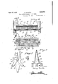
- Figure 1 is a fragmentary vertical section through a furnace illustrating in end elevation, an application of the present invention therewith.
- Figure 2 is a fragmentary vertical section in detail through the furnace similar to Figure 1, illustrating the rocking movement of the grate bars in accordance with the present invention.
- Figure 3 is a fragmentary transverse section in detail through a furnace taken substant-ially on line 33 of Figure 2.
- Figure 4 is atop plan view ofene of the grate bars.
- Figure 5 1s a vertical section in detail taken Figure 6 is a section taken substantially on line 6-6 of Figure 4:. I V
- Figure "l” is a section through one of the legs of the-grate taken substantially on line 7-7 of Figure 5.
- F indicates vertically extending furnace walls be tween which the grate of thefpresent invention is disposed.
- a pair of oppositely disposed, alined, longitudinally extending jour nal bars 89, are secured to the side walls of the furnace for the purpose of supporting the grate in accordance with the present invention.
- the grate for the furnace consists of a plurality of horizontally disposed grate bars indicated generally at 10 that are mounted for oscillatory movement on trunnions 11, 12 at each end of each grate bar that are journalled on thebars 8, 9.
- each rate bar is provided with a leg 13 that is journalled to a shaker bar 14, the outer end 15 of which is connected to a shaker lever 16,
- Each of the grate bars 10 is formed with solid ends 18 having upstanding-raking arms 19 formed integral therewith and projecting above the upper face of the grate bar.
- Each section 20 is transversely spaced to provide pockets 23 between the respective sections for the purpose of permitting air to flow through the grate.
- the bight portion -24 of each section 20 is flat on its-upper face and rising along'the median line of said bight portion there is an integral rib 25 that merges at its opposite ends with the'raking arms 19; Projecting above the rib are a plurality of the bed of coals.
- the interior grate sections 20 are interconnected along the ends of the legs by solid sections 27 and the bight portions 24: of each section are interconnected by the rib 25, so
- a hollow member 32 of conical construction Disposed above the sharp curvesBO, 31", and supported on the bight portion 24 of the section 20 is a hollow member 32 of conical construction.
- the base of the hollow member 32 extends onthe opposite sides of the bight portion 24 of one section 20 into the pockets 23 for providing internal draft through the bed of coals.
- the side walls of the member 32 are provided with staggered openings 33 to provide communication with the interior of the member.
- grate bars are reversible end for end.
- a grate bar comprising a plurality of I substantially inverted U-shaped sections interconnected together and arranged in spaced relation, each of said U-shaped sections having the legs thereof oppositely curved,
- each of said inverted,- U-shaped sections provided at the bight'port-ion thereof with a projection for stirring the coals during-shaking operation.
- grate bar means for rockably' su f porting-the same, said grate bar beingsu stantially of inverted U-shape in cross section, and'havingthe legs of theinverted' U oppositely curved, a projectionextending up-l Y ing of such a radius as to provide at opposite sides-of the grate bar sharpened projections,
- the bight portion of the inverted U provide a series of substantially five relatively "spaced which together with-the free end of the leg portlons and the projection rising from the points or projections extending substantially laterally to the axisof the grate bar.
Landscapes
- Engineering & Computer Science (AREA)
- Chemical & Material Sciences (AREA)
- Combustion & Propulsion (AREA)
- Mechanical Engineering (AREA)
- General Engineering & Computer Science (AREA)
- Solid Fuels And Fuel-Associated Substances (AREA)
Description
Ap 1932- A. PISCIOTTA FIVE-CORNERED BUCKWHEAT COAL GRATE Filed Sept. 26, 1929 2 Sheets-Sheet Ania n3 7 1156202240 0 d I F 44 h 0000 0 a N. 4 n 3/8 2 3 3 M oooo .9 m V d A w Attorney April 2, 3 A. PISCIOTTA FIVE-CORNEREP BUCKWHEAT COAL GRATE Filed Sept. 26, 1929 2 Sheets-Sheet 2 mumnmw nib my 733mb Zia,
A ttor ney Patented Apr. 12, 1932 PATENT OFFICE ANTONY rIseIo'r'rA, OFYELIVIHURST, NEW YORK FIVE-GORNERED BUCKWHEAT COAL GRATE Application filed September 26, 1929. Serial No. 395,332.
This invention relates to furnace grates and is particularly adaptable to burning buckwheat coal.
An object of the invention is to provide a grate, the configuration of which provides substantially on line 55 of Figure 3.
five points or corners that materially aid in stirring up the fireduring the raking operation.
Another object of the invention is to provide projections on the grate bars that rock during the raking operation for the purpose of breaking up clinkers and stirring the bed of coals.
Another object of the invention is to pro} vide a hollow column on each grate that provides interior drafts for the bed of coals and furthermore to provide a grate that is self raking in operation and that supplies plenty of air for burning buckwheat coal.
Further objects of the'invention are to provide, in a manner as hereinafterset forth, a grate of the character referred to, that is strong, compact and durable, thoroughly reliable for its intended purpose, very simple in its method of assembly and comparativelyinexpensive to manufacture and installfl With the foregoing and other objects in view, the invention consists of a novel con struction, combination and arrangement of 39 parts as will be hereinafter more specifically described and illustrated in the accompanying drawings, wherein is disclosed an embodiment of the invention, but it is to be understood that changes, variations and modifications may be resorted to withoutdeparting from the spirit of the claims hereto appended. v
In the drawings, wherein like reference characters denote corresponding parts throughout the several views:
Figure 1 is a fragmentary vertical section through a furnace illustrating in end elevation, an application of the present invention therewith.
Figure 2 is a fragmentary vertical section in detail through the furnace similar to Figure 1, illustrating the rocking movement of the grate bars in accordance with the present invention.
Figure 3 is a fragmentary transverse section in detail through a furnace taken substant-ially on line 33 of Figure 2.
Figure 4 is atop plan view ofene of the grate bars.
Figure 5 1s a vertical section in detail taken Figure 6 is a section taken substantially on line 6-6 of Figure 4:. I V
Figure "l" is a section through one of the legs of the-grate taken substantially on line 7-7 of Figure 5.
Considerable difficulty has been experienced in burning buckwheat coal, owing to the fact that the particles of coal arein the finely comminut-ed state, and moreover becausethe dirt or shale and slate containedin the coal has the effect of producing clinkers in the bed of coal. On the other hand, because of the'fineness of the granulations of the buck wheat coal, there is very little space or interstices between the particles of coal in the bed to permit passage of air therethrough, and when a bed of coals of any thickness is utilized, it'has beenfoun-d that there are burnt out or dead spots occurring in the bed of coals *which affects the heating efliciency of the furnace. I
It is therefore within the contemplation of the present invention to provide a grate structure that w1ll promote contlnuous burning throughout the entire bed of coals, to provide internal draftfor the bed of coals, and moreover to provide projections on the grate that will stir and break up clinkers in the bed of coals during the raking operation of the rate.
* Referring to the drawings in detail, F indicates vertically extending furnace walls be tween which the grate of thefpresent invention is disposed. A pair of oppositely disposed, alined, longitudinally extending jour nal bars 89, are secured to the side walls of the furnace for the purpose of supporting the grate in accordance with the present invention. The grate for the furnace consists of a plurality of horizontally disposed grate bars indicated generally at 10 that are mounted for oscillatory movement on trunnions 11, 12 at each end of each grate bar that are journalled on thebars 8, 9. v a
-.-lugs 26 that serve to break up clinkers in" 32 there is an openings83 leading from the Depending from the same end, each rate baris provided with a leg 13 that is journalled to a shaker bar 14, the outer end 15 of which is connected to a shaker lever 16,
pivoted as at 17 to the outside of the furnace F.
Each of the grate bars 10 is formed with solid ends 18 having upstanding-raking arms 19 formed integral therewith and projecting above the upper face of the grate bar. The
lower ends of the arms 19 mergew-ith thetrunnions 11, 12. Between the solid end sections 18, there are a plurality of inverted,
U-shaped sections 20, the legs 21, 22 of which are curved.
Each section 20 is transversely spaced to provide pockets 23 between the respective sections for the purpose of permitting air to flow through the grate. The bight portion -24 of each section 20 is flat on its-upper face and rising along'the median line of said bight portion there is an integral rib 25 that merges at its opposite ends with the'raking arms 19; Projecting above the rib are a plurality of the bed of coals.
The interior grate sections 20 are interconnected along the ends of the legs by solid sections 27 and the bight portions 24: of each section are interconnected by the rib 25, so
as to form one continuous grate 10.- Along theinterconnecting piece 27 at the bottom of the legs this piece is scored as at 28 to provide teeth 29between the scorings for breaking clinkers; Where the curved legs 21, 22 merge with the bight portion 24 as indicated at 30 and 31,th radius of the curve is such that when thegrat'e' bars 10 are at rest, substantially heart shaped pockets are provided between adjacent grate bars.
Disposed above the sharp curvesBO, 31", and supported on the bight portion 24 of the section 20 is a hollow member 32 of conical construction. The base of the hollow member 32 extends onthe opposite sides of the bight portion 24 of one section 20 into the pockets 23 for providing internal draft through the bed of coals. The side walls of the member 32 are provided with staggered openings 33 to provide communication with the interior of the member.
Itv is also to be understood that the grate bars are reversible end for end.
Atthe extreme top of the conicalmembers there is provided a heart shaped pocket 34 when the gratebars are at rest.
When the grate bars 10 are raked, at the end of the stroke, they assume the position shown in Figure 2 of the drawings and from this position it will be apparent that a crushing efiect is produced by the walls surroundingthe pocket 34. v From the foregoing construction it will be seen that a grate bar has been provided that has five points or corners thereon for stirring up the bedofcoalsand breaking clinkers, the five points being, each end of the legs which provides two "points, two more points where the legs merge with the bight portion and the fifth is provided by'thetransverse rib 25-with its projection 26.:
It is to be understood that by describingin detailherein, any particular form, structure, or arrangement,it is not intended to limit-the invention beyond the terms of the several claims, or the requirements of theprior art.
Having described my invention, what I claim is 1. A grate bar comprising a plurality of I substantially inverted U-shaped sections interconnected together and arranged in spaced relation, each of said U-shaped sections having the legs thereof oppositely curved,
with the convex edges of the legs being; ar-' ranged'in opposed relation, a hollowmember supported on saidgrate bar, said hollow mem. her being opened at oneend,-and the wall. of the hollow member being, perforated, and
each of said inverted,- U-shaped sections provided at the bight'port-ion thereof with a projection for stirring the coals during-shaking operation.-
'2..A grate bar, means for rockably' su f porting-the same, said grate bar beingsu stantially of inverted U-shape in cross section, and'havingthe legs of theinverted' U oppositely curved, a projectionextending up-l Y ing of such a radius as to provide at opposite sides-of the grate bar sharpened projections,
bight portion of the inverted U provide a series of substantially five relatively "spaced which together with-the free end of the leg portlons and the projection rising from the points or projections extending substantially laterally to the axisof the grate bar.
Intestimony whereof I affix my signature' ANTONY PISCIOTTA,
Priority Applications (1)
| Application Number | Priority Date | Filing Date | Title |
|---|---|---|---|
| US395332A US1853574A (en) | 1929-09-26 | 1929-09-26 | Five-cornered buckwheat coal grate |
Applications Claiming Priority (1)
| Application Number | Priority Date | Filing Date | Title |
|---|---|---|---|
| US395332A US1853574A (en) | 1929-09-26 | 1929-09-26 | Five-cornered buckwheat coal grate |
Publications (1)
| Publication Number | Publication Date |
|---|---|
| US1853574A true US1853574A (en) | 1932-04-12 |
Family
ID=23562597
Family Applications (1)
| Application Number | Title | Priority Date | Filing Date |
|---|---|---|---|
| US395332A Expired - Lifetime US1853574A (en) | 1929-09-26 | 1929-09-26 | Five-cornered buckwheat coal grate |
Country Status (1)
| Country | Link |
|---|---|
| US (1) | US1853574A (en) |
-
1929
- 1929-09-26 US US395332A patent/US1853574A/en not_active Expired - Lifetime
Similar Documents
| Publication | Publication Date | Title |
|---|---|---|
| US1853574A (en) | Five-cornered buckwheat coal grate | |
| US1625556A (en) | Fire grate | |
| US593539A (en) | Stove or furnace grate | |
| US702891A (en) | Grate-bar. | |
| US1052493A (en) | Shaker-grate. | |
| US644302A (en) | Grate. | |
| US273437A (en) | Grate | |
| US1321252A (en) | Fxtrn ace-grate | |
| US703455A (en) | Stove-grate. | |
| US529504A (en) | Grate | |
| US693880A (en) | Grate for boiler-furnaces. | |
| US192331A (en) | Improvement in boiler-furnace grate-bars | |
| US968735A (en) | Grate. | |
| US1613316A (en) | Chain grate | |
| US1548834A (en) | Ash-discharge amd clinjkeb-gbindeb structure | |
| US836616A (en) | Grate-operating mechanism. | |
| US1232687A (en) | Furnace-grate. | |
| US838906A (en) | Grate-bar. | |
| US1670358A (en) | Mechanical stoker | |
| US471695A (en) | heider | |
| US450315A (en) | Grate | |
| US949065A (en) | Grate. | |
| US1421419A (en) | Mechanical stoker | |
| US423465A (en) | ashgeoft | |
| US291864A (en) | Lemuel bannister |