US185355A - Improvement in signaling apparatus and circuits for alarm-telegraphs - Google Patents
Improvement in signaling apparatus and circuits for alarm-telegraphs Download PDFInfo
- Publication number
- US185355A US185355A US185355DA US185355A US 185355 A US185355 A US 185355A US 185355D A US185355D A US 185355DA US 185355 A US185355 A US 185355A
- Authority
- US
- United States
- Prior art keywords
- circuit
- alarm
- wheel
- magnet
- rod
- Prior art date
- Legal status (The legal status is an assumption and is not a legal conclusion. Google has not performed a legal analysis and makes no representation as to the accuracy of the status listed.)
- Expired - Lifetime
Links
Images
Classifications
-
- B—PERFORMING OPERATIONS; TRANSPORTING
- B29—WORKING OF PLASTICS; WORKING OF SUBSTANCES IN A PLASTIC STATE IN GENERAL
- B29C—SHAPING OR JOINING OF PLASTICS; SHAPING OF MATERIAL IN A PLASTIC STATE, NOT OTHERWISE PROVIDED FOR; AFTER-TREATMENT OF THE SHAPED PRODUCTS, e.g. REPAIRING
- B29C48/00—Extrusion moulding, i.e. expressing the moulding material through a die or nozzle which imparts the desired form; Apparatus therefor
- B29C48/25—Component parts, details or accessories; Auxiliary operations
- B29C48/256—Exchangeable extruder parts
- B29C48/2562—Mounting or handling of the die
-
- B—PERFORMING OPERATIONS; TRANSPORTING
- B29—WORKING OF PLASTICS; WORKING OF SUBSTANCES IN A PLASTIC STATE IN GENERAL
- B29C—SHAPING OR JOINING OF PLASTICS; SHAPING OF MATERIAL IN A PLASTIC STATE, NOT OTHERWISE PROVIDED FOR; AFTER-TREATMENT OF THE SHAPED PRODUCTS, e.g. REPAIRING
- B29C48/00—Extrusion moulding, i.e. expressing the moulding material through a die or nozzle which imparts the desired form; Apparatus therefor
- B29C48/03—Extrusion moulding, i.e. expressing the moulding material through a die or nozzle which imparts the desired form; Apparatus therefor characterised by the shape of the extruded material at extrusion
Definitions
- My invention relates to municipal and district telegraphs in which signal boxes or stations are arranged in a closed electric circuit, and provided with a circuit-breaking device actuated by suitable mechanism, in such manner that one or more arbitrary signals may be transmitted to a central or main stationwhenever such mechanism is designedly set in motion, as by a person desiring to transmit asignal; and the present invention particularly relates to the combination, with such signal-boxes and circuits, of means for automatically transmitting a signal when a circuit is undesignedly broken, as by a burglar entering a house, or by a fire breaking out, &c.
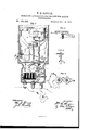
- FIG. l is a front elevation of a district signal box illustrating my invention, the outer case thereof being shown in section.
- Fig. 2 is an edge view of the circuit-breaking wheel and its attachments.
- Fig. 3 is a detached side view of a portion of the apparatus, and
- Fig. 4 is a diagram of the circuits of the differential magnet.
- A(see Fig. 1) represents the metallic box or case inclosing an ordinary signaling apparatus, such as is used for district telegraphs.
- G is the circuit-breaking wheel,which is driven, in the direction shown by the arrow marked thereon, by a coiled spring and clock-work, which is shown as inclosed within a cylindrical case, B.
- a contact-spring, D presses against the periphery of the circuit-wheel O as it revolves, except where the latter is cut away to form circuit-breaking spaces, as shown at c.
- the circuit-breaking wheel is held in check by the pin a, which is in contact with the check-rod E, which latter is provided with a ring, E, at its lower end, by which to operate it.
- the electric circuit whichis a constantlyclosed circuit, enters by the screw-post F; thence passes by the wire 1 to the contactpoints m m, which are now supposed to be in contact; thence, by wires 2 and 3, to the key K; thence, by wire 4, to check rod E, pin 0, and circuit-wheel O, which latter is in electrical connection with the outer case A, through which the connection is formed with the screwpost F, and from thence the wire 5 goes to the next station.
- the knob K By depressing the knob K the key K breaks the circuit, and the current is forced to pass from 3 through the helices of the sounder S, and thence, by wires 6 and 7 and contact spring D, to the circuit-wheel C.
- the automatic apparatus is released or controlled by an armature, N, and detent J whenever the electro-magnet M attracts the armature N.
- the magnet M is a differential magnet, and may be of any of the forms of differential magnets so well known in connection with duplex telegraphy. For illustration, I have shown that form in which two coils are oppositely wound, side by side, on the same core, so that their magnetic effects are neutralized, and the core remains inactive.
- the other coil is in a circuit containing a resistance, R, equal to the resistance of the alarnrcircuit 12 12, so
- any of the known forms of differential magnets may be'used, and there may be employed any of theknown methods used in duplex telegraphy wherein the branches of an electric circuit are f so arranged in relation to an electro-magnet qfitwo paths before it--one via 12 FA. BA and one. section of the magnet M to at, the other through 9 and the other section of the magnet' 10 It to a7both of equal resistance.
- the current divides equally, and the It, now, however, the alarm-circuit be anywhere broken, the whole current is forced through the circuit last described, the equilibrium is destroy ed, the magnet becomes active, attracts goits armature, and starts the apparatus, as
- Fig. l the check-rod E is shown as disengaged from the pin 0 of the ordinary circuit-breaking wheel 0, and my automatic apparatus is adjusted in position for operating upon breaking the alarm-circuit.
- an additional check-lever, G is provided, and it is pivoted at g, and armed with a detent, g, at its extremity.
- the checklever G is held up, so as to engage the pin 0 of the circuit-wheel, by an upright rod, H, which is, in its turn, supported by its lower extremity resting upon the shoulder of a detent, J, which is suspended from the pivotj and held in place by the spiral spring j.
- the route of the electric current through the apparatus is changed, the contact between E and c, and also between m and m, having been interrupted, and a new one formed between the contact-points e and e, the former of which is in connection with the rod E and the latter with the wire 8.
- the route of the main circuit may now be traced as follows: From the screw-post F, by the routes before described, to point .90; thence by wire 3 to key K, and WllBJL-tO check-rod E, as before; thence tak-- ing the new route, by contactpoints 6 0?, wires 8 and 7, and contact-spring D, to circuit-wheel O, and thence to screw-post F, as before.
- the alarm-circuit 12 may be carried through the building, as described, and provided with "circuit-breakersattached to the doors, windows, skylights, or other openings, so that any attempt to enter them will necessarily interrupt or break this alarm-circuit.
- the alarmcircuit may be provided with thermostats or other suitable devices, so arranged that any unusual increase of temperature will likewise cause the circuit to be broken; or suitable devices may be attached which will produce the same eifect upon the bursting of a water-pipe. Any other desired attachment can be arranged to act upon the wire 12, forming the alarm-circuit. The manner in which the interruption of this circuit is made to transmit a signal or alarm will now be explained.
- an insulated pin it, on the rod H presses the two contactpoints m and m together, short-circuiting or shunting the magnet 31 by the wires 1 and 2, except when'the said rod is retained in an elevated position by the detent J but the latter may be tripped when desired, without the aid of the magnet, by pushing the pin at.
- a signal-box arranged to be manually or automatically operated, the combination, with the circuit-wheel and means for automatically releasing the same, of a stop device, substantially as shown, allowing a definite number of rotations of the circuit-wheel, so as to distinguish between the ordinary and automatic signals, substantially as set forth.
- circuit-breaking wheel (1, a magnet, M, and its armature N, a stop, 0 g, and an arresting device, P, Whereby the number of revolutions of said circuitbreaking wheel may be regulated after it has been released by the action of said magnet upon its armature.
Landscapes
- Engineering & Computer Science (AREA)
- Mechanical Engineering (AREA)
- Burglar Alarm Systems (AREA)
Description
W. H. SAWYER.'
SIGNALING APPARATUS AND CIRCUITS FOR ALARM I TELEGRAPHS. -No.185,355. Patented Dec. 12, 1876.
Jay].
j Z c z (g a 2 j c 1 Z I g i Q 7 9 4 6 5. 2 z 8 YIIIIIII/I/II/l/ Z 1 .3. e U a z I J I THE GRAPHIC C0-N.Y-
WILLIAM H. SAWYER, OF NEW YORK, N. Y.
IMPROVEMENT IN SIGNALING APPARATUS AND CIRCUITS FOR ALARM-TELEGRAPHS.
Specification forming partof Letters Patent No. 185,355, dated December 12, 1876; application filed September 29, 1874.
To all whom it may concern Be it known that I, WILLIAM H. SAWYER, ofthe city of New York, in the county and State of New York, have invented certain new and useful Improvements in Telegraph Apparatus for Automatic Signaling; and I do hereby declare that the following is a full, clear, and exact description of the same, reference being bad to the accompanying drawing, which forms a part of this specification.
My invention relates to municipal and district telegraphs in which signal boxes or stations are arranged in a closed electric circuit, and provided with a circuit-breaking device actuated by suitable mechanism, in such manner that one or more arbitrary signals may be transmitted to a central or main stationwhenever such mechanism is designedly set in motion, as by a person desiring to transmit asignal; and the present invention particularly relates to the combination, with such signal-boxes and circuits, of means for automatically transmitting a signal when a circuit is undesignedly broken, as by a burglar entering a house, or by a fire breaking out, &c.
To this end my invention consists in those novel features and combinations more particularly hereinafter described and claimed, reference being had to the accompanying sheet of drawings, in which Figure l is a front elevation of a district signal box illustrating my invention, the outer case thereof being shown in section. Fig. 2 is an edge view of the circuit-breaking wheel and its attachments. Fig. 3 is a detached side view of a portion of the apparatus, and Fig. 4 is a diagram of the circuits of the differential magnet.
A(see Fig. 1) represents the metallic box or case inclosing an ordinary signaling apparatus, such as is used for district telegraphs. G is the circuit-breaking wheel,which is driven, in the direction shown by the arrow marked thereon, by a coiled spring and clock-work, which is shown as inclosed within a cylindrical case, B. A contact-spring, D, presses against the periphery of the circuit-wheel O as it revolves, except where the latter is cut away to form circuit-breaking spaces, as shown at c. When used for ordinary signaling the circuit-breaking wheel is held in check by the pin a, which is in contact with the check-rod E, which latter is provided with a ring, E, at its lower end, by which to operate it.
Thus it will be understood that, ordinarily, when the check-rod E is drawn down by means of the ring E the pin 0 will be released, which will permit the circuit-wheel O to revolve in the direction of the said arrow marked upon it.
When the ring E is released, the spiral spring 8 raises the rod E again into the path of the pin 0, and the circuit-wheel G is stopped after having completed its revolution.
The electric circuit, whichis a constantlyclosed circuit, enters by the screw-post F; thence passes by the wire 1 to the contactpoints m m, which are now supposed to be in contact; thence, by wires 2 and 3, to the key K; thence, by wire 4, to check rod E, pin 0, and circuit-wheel O, which latter is in electrical connection with the outer case A, through which the connection is formed with the screwpost F, and from thence the wire 5 goes to the next station. By depressing the knob K the key K breaks the circuit, and the current is forced to pass from 3 through the helices of the sounder S, and thence, by wires 6 and 7 and contact spring D, to the circuit-wheel C. By thus diverting the circuit through the sounder S it may be known before sending a signal whether any other station isusing the line.
The hereinbefore-described apparatus is all well known, and in itself forms no part of my present invention.
I will now proceed to describe the automatic part of the apparatus and the arrangement for operating it.
The automatic apparatus is released or controlled by an armature, N, and detent J whenever the electro-magnet M attracts the armature N. The magnet M is a differential magnet, and may be of any of the forms of differential magnets so well known in connection with duplex telegraphy. For illustration, I have shown that form in which two coils are oppositely wound, side by side, on the same core, so that their magnetic effects are neutralized, and the core remains inactive. In
the diagram, Fig. 4, the coils are shown as oppositely and concentrically wound. One of core of the magnet remains unaifected.
{in .the wires 12 12, Fig. 1. The other coil is in a circuit containing a resistance, R, equal to the resistance of the alarnrcircuit 12 12, so
as to insure an equal division of the current bet-ween the two circuits.
| WVhile this style of magnet is shown, any of the known forms of differential magnets may be'used, and there may be employed any of theknown methods used in duplex telegraphy wherein the branches of an electric circuit are f so arranged in relation to an electro-magnet qfitwo paths before it--one via 12 FA. BA and one. section of the magnet M to at, the other through 9 and the other section of the magnet' 10 It to a7both of equal resistance. Hence the current divides equally, and the It, now, however, the alarm-circuit be anywhere broken, the whole current is forced through the circuit last described, the equilibrium is destroy ed, the magnet becomes active, attracts goits armature, and starts the apparatus, as
ereafter described. It will be also noticed that if any attempt is made on the alarm-circnit which alters its resistance, the same re sult will follow.
In Fig. l the check-rod E is shown as disengaged from the pin 0 of the ordinary circuit-breaking wheel 0, and my automatic apparatus is adjusted in position for operating upon breaking the alarm-circuit. In order to accomplish this an additional check-lever, G, is provided, and it is pivoted at g, and armed with a detent, g, at its extremity. The checklever G is held up, so as to engage the pin 0 of the circuit-wheel, by an upright rod, H, which is, in its turn, supported by its lower extremity resting upon the shoulder of a detent, J, which is suspended from the pivotj and held in place by the spiral spring j. In order, therefore, to connect the automatic apparatus, it is only necessary to lift up the rod H by the handle H, when the detent g will engage with the pin 0, while at the same time the shoulder of the detent J will slip under the lower end of the rod H, and retain it in that position. When this has been done the checkrod E is drawn down, and secured in that position by means of the stop E (shown in side elevation in Fig. 3;) but the circuit-wheel O is not released, it being now held by the detent 9. By this operation, also, the route of the electric current through the apparatus is changed, the contact between E and c, and also between m and m, having been interrupted, and a new one formed between the contact-points e and e, the former of which is in connection with the rod E and the latter with the wire 8. The route of the main circuit may now be traced as follows: From the screw-post F, by the routes before described, to point .90; thence by wire 3 to key K, and WllBJL-tO check-rod E, as before; thence tak-- ing the new route, by contactpoints 6 0?, wires 8 and 7, and contact-spring D, to circuit-wheel O, and thence to screw-post F, as before.
The alarm-circuit 12 may be carried through the building, as described, and provided with "circuit-breakersattached to the doors, windows, skylights, or other openings, so that any attempt to enter them will necessarily interrupt or break this alarm-circuit. The alarmcircuit may be provided with thermostats or other suitable devices, so arranged that any unusual increase of temperature will likewise cause the circuit to be broken; or suitable devices may be attached which will produce the same eifect upon the bursting of a water-pipe. Any other desired attachment can be arranged to act upon the wire 12, forming the alarm-circuit. The manner in which the interruption of this circuit is made to transmit a signal or alarm will now be explained.
It will be understood that when the alarmcircuit is broken or interrupted in any way whatever the entire electric current traversing the main wire will be forced to pass through one of the helices of the electro-magnet M, which is thus caused to attract its armature N. The movement of the armature pushes the detent J from under the rod H, which latter is instantly drawn down by the spiral spring h, thereby releasing the circuit-wheel O, which begins to revolve by the action of the clock-work. In order to distinguish the signal thus automatically transmitted by means of the breaking of the alarm-circuit from that given by simply pulling the rod E, the mechanism is so arranged that the former will be repeated a number of times before the circuit-wheel is checked in its revolution.
This I accomplish by the following device: Upon the arbor of the circuit-wheel G is fixed a cylinder, L, which revolves with it, and has a screw or worm, 1, formed upon its surface, as clearly shown in Fig. 2. A follower, P, is mounted upon a curved arm, Q, which is rigidly attached to the check-rod E. The follower is made so as to turn upon its support at q, while its free end 19 is pressed horizontally toward the circuit-wheel O by means of the spiral spring 10, but at the same time is prevented from touching it by the stop q. When, therefore, the check-rod E is drawn down and secured by means of the stop E, as hereinbefore explained, the follower P is also brought down, and its free end 1) engages with the thread of the screw; consequently, when the detent J is tripped by the action of the electromagnet M and the circuit-wheel 0 released, the latter is permitted to revolve during the length of time that the point p of the follower P is traversing the said screw-thread, until, after having made as many revolutions as there are turns of the screw-thread Z around the cylinder L, the motion of the circuit-wheel is arrested by the pin 1', which is set in the path of the screw l, coming in contact with the follower, and thus the further repetition of the signal is prevented. Thus a signal which is transmitted automatically is easily distinguished from one sent by a person pulling the check-rod E, by the former being repeated a specified number of times, previously decided upon.
In order to remove the resistance of the magnet M from the circuit when the autoin atie alarm is not intended to operate, an insulated pin, it, on the rod H presses the two contactpoints m and m together, short-circuiting or shunting the magnet 31 by the wires 1 and 2, except when'the said rod is retained in an elevated position by the detent J but the latter may be tripped when desired, without the aid of the magnet, by pushing the pin at.
What I claim as my invention, and desire to secure by Letters Patent, is-
1. The combination, with automatic signal-.
ing apparatus, substantially of the kind described, of a differential magnet having one coilin a circuit containing alarm apparatus, and the other coil in a circuit containing aresistance, substantially as shown and described.
2. The combination, with automatic signaling apparatus, substantially such as described, of a circuit divided at the locality to be signaled from or guarded, one branch containing the automatic alarm apparatus and one coil of a difierential magnet, and the other a suitable resistance, substantially as shown and described. a
3. In a signal-box arranged to be manually or automatically operated, the combination, with the circuit-wheel and means for automatically releasing the same, of a stop device, substantially as shown, allowing a definite number of rotations of the circuit-wheel, so as to distinguish between the ordinary and automatic signals, substantially as set forth.
4. The combination of a circuit-breaking wheel, (1, a magnet, M, and its armature N, a stop, 0 g, and an arresting device, P, Whereby the number of revolutions of said circuitbreaking wheel may be regulated after it has been released by the action of said magnet upon its armature.'
5. The combination of the screw or worm l, I
WM. H. SAWYER.
Witnesses M. M. LIVINGSTON, A. J. DE LACY.
Publications (1)
| Publication Number | Publication Date |
|---|---|
| US185355A true US185355A (en) | 1876-12-12 |
Family
ID=2254761
Family Applications (1)
| Application Number | Title | Priority Date | Filing Date |
|---|---|---|---|
| US185355D Expired - Lifetime US185355A (en) | Improvement in signaling apparatus and circuits for alarm-telegraphs |
Country Status (1)
| Country | Link |
|---|---|
| US (1) | US185355A (en) |
-
0
- US US185355D patent/US185355A/en not_active Expired - Lifetime
Similar Documents
| Publication | Publication Date | Title |
|---|---|---|
| US185355A (en) | Improvement in signaling apparatus and circuits for alarm-telegraphs | |
| US155207A (en) | Improvement in district alarm-telegraphs | |
| US594281A (en) | Signments | |
| US341115A (en) | District or fire-alarm telegraph | |
| US460464A (en) | Automatic electric fire-alarm system | |
| US254611A (en) | Egbert carter | |
| US990434A (en) | Electrical system for the supervision of watchmen. | |
| US667727A (en) | Automatic alarm system. | |
| US361020A (en) | Telegraphic alarm-signal | |
| US388358A (en) | guest | |
| US341114A (en) | Fire-alarm telegraph | |
| US420173A (en) | Electric fire-alarm system | |
| USRE8891E (en) | Improvement in non-interfering fire-alarm apparatus | |
| US964086A (en) | Fire-alarm system. | |
| US563336A (en) | Electric signaling apparatus | |
| US380241A (en) | Fire and burglar alarm system | |
| US594034A (en) | price | |
| US487676A (en) | Electric signaling apparatus | |
| US500563A (en) | Signaling system | |
| US880160A (en) | Burglar-alarm system and apparatus therefor. | |
| US402507A (en) | chase | |
| US681290A (en) | Burglar-alarm. | |
| US748501A (en) | Electric signalling apparatus. | |
| US760955A (en) | Electric signaling system and apparatus employed therein. | |
| US724917A (en) | Automatic audible fire-alarm transmitter and signal. |