US1853557A - Formation testing - Google Patents
Formation testing Download PDFInfo
- Publication number
- US1853557A US1853557A US281136A US28113628A US1853557A US 1853557 A US1853557 A US 1853557A US 281136 A US281136 A US 281136A US 28113628 A US28113628 A US 28113628A US 1853557 A US1853557 A US 1853557A
- Authority
- US
- United States
- Prior art keywords
- valve
- pipe
- packer
- wash pipe
- well
- Prior art date
- Legal status (The legal status is an assumption and is not a legal conclusion. Google has not performed a legal analysis and makes no representation as to the accuracy of the status listed.)
- Expired - Lifetime
Links
- 230000015572 biosynthetic process Effects 0.000 title description 20
- 238000012360 testing method Methods 0.000 title description 10
- 238000005553 drilling Methods 0.000 description 9
- 238000004891 communication Methods 0.000 description 6
- 230000000694 effects Effects 0.000 description 6
- 239000012530 fluid Substances 0.000 description 6
- 238000012856 packing Methods 0.000 description 5
- 238000000034 method Methods 0.000 description 4
- 238000007789 sealing Methods 0.000 description 4
- 230000001276 controlling effect Effects 0.000 description 3
- 239000007788 liquid Substances 0.000 description 3
- 230000003068 static effect Effects 0.000 description 3
- 210000004907 gland Anatomy 0.000 description 2
- 239000000463 material Substances 0.000 description 2
- 241001527902 Aratus Species 0.000 description 1
- 244000025254 Cannabis sativa Species 0.000 description 1
- 235000012766 Cannabis sativa ssp. sativa var. sativa Nutrition 0.000 description 1
- 235000012765 Cannabis sativa ssp. sativa var. spontanea Nutrition 0.000 description 1
- 240000000491 Corchorus aestuans Species 0.000 description 1
- 235000011777 Corchorus aestuans Nutrition 0.000 description 1
- 235000010862 Corchorus capsularis Nutrition 0.000 description 1
- VVNCNSJFMMFHPL-VKHMYHEASA-N D-penicillamine Chemical compound CC(C)(S)[C@@H](N)C(O)=O VVNCNSJFMMFHPL-VKHMYHEASA-N 0.000 description 1
- 235000009120 camo Nutrition 0.000 description 1
- 150000001768 cations Chemical class 0.000 description 1
- 235000005607 chanvre indien Nutrition 0.000 description 1
- 238000010276 construction Methods 0.000 description 1
- 230000008878 coupling Effects 0.000 description 1
- 238000010168 coupling process Methods 0.000 description 1
- 238000005859 coupling reaction Methods 0.000 description 1
- 229940075911 depen Drugs 0.000 description 1
- 229910003460 diamond Inorganic materials 0.000 description 1
- 239000010432 diamond Substances 0.000 description 1
- 239000011487 hemp Substances 0.000 description 1
- 238000012423 maintenance Methods 0.000 description 1
- 238000004519 manufacturing process Methods 0.000 description 1
- 229940099990 ogen Drugs 0.000 description 1
- 230000008092 positive effect Effects 0.000 description 1
- 238000003825 pressing Methods 0.000 description 1
- 238000005086 pumping Methods 0.000 description 1
- 230000001105 regulatory effect Effects 0.000 description 1
- 238000005070 sampling Methods 0.000 description 1
- VCSAHSDZAKGXAT-AFEZEDKISA-M sodium;(z)-(1-carbamoyl-5-chloro-2-oxoindol-3-ylidene)-thiophen-2-ylmethanolate Chemical compound [Na+].C12=CC(Cl)=CC=C2N(C(=O)N)C(=O)\C1=C(/[O-])C1=CC=CS1 VCSAHSDZAKGXAT-AFEZEDKISA-M 0.000 description 1
- XLYOFNOQVPJJNP-UHFFFAOYSA-N water Substances O XLYOFNOQVPJJNP-UHFFFAOYSA-N 0.000 description 1
Images

Classifications
-
- E—FIXED CONSTRUCTIONS
- E21—EARTH OR ROCK DRILLING; MINING
- E21B—EARTH OR ROCK DRILLING; OBTAINING OIL, GAS, WATER, SOLUBLE OR MELTABLE MATERIALS OR A SLURRY OF MINERALS FROM WELLS
- E21B34/00—Valve arrangements for boreholes or wells
- E21B34/06—Valve arrangements for boreholes or wells in wells
- E21B34/14—Valve arrangements for boreholes or wells in wells operated by movement of tools, e.g. sleeve valves operated by pistons or wire line tools
-
- E—FIXED CONSTRUCTIONS
- E21—EARTH OR ROCK DRILLING; MINING
- E21B—EARTH OR ROCK DRILLING; OBTAINING OIL, GAS, WATER, SOLUBLE OR MELTABLE MATERIALS OR A SLURRY OF MINERALS FROM WELLS
- E21B49/00—Testing the nature of borehole walls; Formation testing; Methods or apparatus for obtaining samples of soil or well fluids, specially adapted to earth drilling or wells
- E21B49/08—Obtaining fluid samples or testing fluids, in boreholes or wells
- E21B49/081—Obtaining fluid samples or testing fluids, in boreholes or wells with down-hole means for trapping a fluid sample
Definitions
- Special objects of this invention are to ena ble the testing of the formation in wells, irrespective of the methods by which such wells are drilled, to provide reliable appara- 4tus for the purpose of and by which tests may be made atany level between the surface and the bottom'of the hole, as the drilling rogresses or after the drilling of the well has been finished and regardless of the diamw eter of the hole; to enable such.
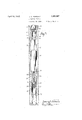
- Fig. 1 is a broken side elevation illustrating the tester as lowered into the hole at the lower end of the drill pipe or at the foot of several sections of pipe forming a container for the sample to be recovered;
- Fig. 2 is a somewhat enlarged and broken sectional view of the tester in the condition shown in the -irst view, that is with the anchor pipe just 4;, touching bottom and before the relatively telescopic parts have shifted to expand the packer and open the valve;
- Fig. 3 is a view generally similar to Fig. 2 b utshowing the parts as shifted to expand the packer and su open the valve;
- Fig. 4 is a sectional view ilend with the under-cut shoulde'rnl of the slidlustrating a modified form of the valve mechanism.
- the apparatus is made as a unitary structure in the nature of a tool, which can be secured to the lower end of the drill string in place of the bit in case of rotar drilling or be lowered into the well by aca le, rods or the like, in the case of other methods of drilling.
- a con- 00 nectingcollar is indicated at 7 having a screw 8 to it the screw socket 9 in a drill collar 10, which is attached to the lower end of the drill'string. Itis to be understood however that other modes of attachment or means of 55 supporting the tool ma be employed, depending primarily on t e method of drilling whether it be rotary, by cable tools, diamond drill or a combination of these, or other. methods.
- the collar 7 vin forms' the upper member of an expander for a packer j 11, which is shown in the form of an expansible4 sleeve of rubber, rtibber composition, canvas, jute, hemp, oakum, or other suitable material or materials, engaged at the ufpper end beneath the under-eut shoulder 12 o the connecting collar and at the lower ing barrel 14.
- the lower barrel member 14 held to the upper member 7 by a sliding bearing over the wash pipe piston 15 which is shown as screwed up into the lower end of the connecting collar at 16 and as having a wrench socket 85. 1 6 in its upper end b which it may be screwed in place.
- a hea 17 is shown provided on the lower end of the wash pipe, serving by engagement with a shoulder 18 in the -bar-- rel to limit the downward sliding movement of the barrel as shown in Fig. 2, this being the position of the parts ⁇ with the packing sleeve in the contracted or unexpanded form.
- the member 15 is shown as provided in its lower end with a long screw socket 19 ad- 95 justably receiving the correspondingly screw threaded end portion of a wash pipe 20, which is held in its adjusted relation by a lock nut 21.
- This pipe acts as a valve or valve operating member to control communication 10 .sleeve 24 under one set of conditions land opens, or ogen, to the space w1tlnn the between the drill pipe and the formation sealed olf below the packer.
- the washv plpe is normall closed at the lower end as indicated and as a port or ports 23 in the side of the same back from the closed lower end which is, or are, closed by the surrounding Bv alvg well under a Fi 3.
- valve sleeve 24 is shown as seated 1n a valve body 25 screwed into the lower end of the sliding barrel at 26. Glands 27 and 28 are shown screwed into the upper and lower ierent set of conditions,
- valve head ends of the valve head and as acting on lead or other suitable packing rings 29 to seal the valve sleeve in place ameiect a non-leaking sliding connection with the wash pi e or valve pipe 20.
- the lower gland in particular is adjustable for the purposes of taking up wear on the packings.
- a erforated anchor pipe 32 is shown detacraumly secured to the lower end of the valve head by a coupling sleeve 33.
- This so-called anchor pipe by engagement with the bottom of the hole serves to effect the expansion of the packer and the opening of the valve. It further serves as a guard and strainer about the lower end of the valve pipe, as will be clear from Fig. 3, and by regulating its length or its place in a string of pipe, it will be seen .that the drill pipe may be opened to the surrounding formation directly at the bottom of the hole or at any desired distance above the bottom.
- the formation will be sealed 0H at the level of the packer and the well con- .tents below the packer will be opened up to the pi e at atmospheric pressure and at the level etermined by the length of the anchor pipe, or osition of the apparatus in the drill.
- the valve isclosed and the packer is contracted by simply lifting on the pipe or suspending line, this having the effect of sliding the upper part of the device relative to the lower part so as to retract the upper packer expander and to withdraw the valve pipe into the valve sleeve to close the Valve.
- the sample taken is thus in this action automatically trapped in the pipe and the packer freed from the hole, so that the pipe can be withdrawn with the sample sealed therein, and further, this withdrawal can be effected without releasing the static pressure and fluid contents ⁇ of the well.
- the valving is effected by the wash pipe, ut the valve itself is a separate instrumentality and the wash pipe operates .as an actuating means for such valve.
- the valve is illustrated as a downwardly opening ball check valve 34 closing upwardly' against a seat 35'carried by the valve cage structure 36, which is screwed upwardly into the bore of the valve body 25.
- This valve is normally held upwardly to its Seat by a spring 37, in the downward path of the wash pipe 20', which in this instance is open at its lower end and notched at 38, so that it cannot be closed by the ball.
- this second embodiment of the invention is substantially( as before described in connection lwith the first form, it being evident that'as the bottom of the hole is reached the packer will be expanded to seal off the formation and the wash pipe will open up communication between the formation and the inside of the drill pipe by forcing valve 34 downwardly olf its seat. Thev when the pipe is lifted out of the hole to trap slidin y cable, rods, or the like.
- the expansion packer in addition to sealing against the walls of the well also has a sealing contact with the piston. It .thus serves the double function of sealing the formation and of preventing leakage between the two relatively sliding parts of the apparatus.
- a suliicient number of lengths of 'drill pipe are employed to provide the nec-y essary sampling chamber, and the weight to set the packer and open the valve, the com- ⁇ lete apparatus being lowered into the well
- the invention is thus adaptable for use with various forms of drilling equipment and may be put to service in the course of drilling the well or when the well is completed or even when the well is flowing. Tests may be taken at different depths for instance, for the purpose of determining the point or points of production in a well or a location where water is coming in and all these tests may be conducted the full diameter of the hole.
- the well may be sunk deeper and a testrmade n of the new formation, leaving the old well as it was, to be again used if desired.
- the device also may be used to temporarily close off the well and permit a smaller outow for the purpose of starting a well flowing.
- the packer engages with the side of the well at whatever level it may be expanded, so as to make it unnecessary to provide any seat therefor, and as no rat-hole is required, the sample is taken from the full diameter of the well and hence provides a more accurate and more comprehensive test than can be had where the sample is taken from the reduced sized bore or rat-hole.
- the top length when the device is lowered in the hole by a cable, the top length may be sealed E vat atmospheric pressure, the fluid in the formation then iowing into the pipe until the air trapped therein is compressed equal to the' pressure on the formation. This ordinarily allows a suflicient sample'being taken, the quantity of the sample depending on the length of pipe used.
- Thepacker sleeve may be secured at' one or both ends so as to surely follow the movements of the two telescopically related'pa'rts, for instance, ⁇ by wrapping it with wire at one or bothvends as indicated in Fig. 1.
- pressure may be utilized as b conducting Huid from the space within the' arrel to a point in back of the packer sleeve.
- Fig. 2 a passage 41.extendin from the lower chamberin -the barrel up t rough the wall of the wash pipe piston and in back of the packet sleeve.
- vent ports 31 are indicated as screw-threaded, so that they may be closed, if desired, by screw plugs 31 as indicated in Fig. 1, so asv to cause this chambered portion of the ap aratus to act as a pump for forcing uid 1n back of the packer when the pipe is lowered and to draw outthis fluid' from in back of the packer ,when the pipe is lifted.
- a pump mechanism automatically op- 'erable to positively expand and contract the packer as the pipe is lowered and lifted. Suficient of this pumping effect may be obtained for short'periods, without using the plugs 31 if the vents 31 are small enough.
- the wash pipe may be equipped with an automatic check valve, such as shown at 22 in Figs.'2 and 3, to enable-mud being circulated in the,well for the purpose of killing a blow-out while the tester is being withdrawn.
- This check valve opens downwardly, and while normally held closed by the superior static pressure in the well, is acted on by a closing spring 43 of suiiicient strength to seat the valve against any possible .superior pressure caused by any difference in level between the liquid inside and outside in pulling the pipe out of the well.
- This check valve will vopen the valve when this use of the same is required.
- the end of the wash pipe may be closed by a suitable cap or plug.
- asupporting collar a wash pipe pist-on set in said collar.
- an expansible packer surrounding said wash pipe piston, a barrel slidingly suspended on said wash pipe piston and operable in its upward movement .over the wash pipe piston to expand the packer, a wash pipe adjustably set in the wash pipe piston and cooperating valving means carried by the barrel and wash pipe for controlling communication between well formation and the interior of said wash pipe.
- a supporting collar a wash pipe piston set in said bollar an expansible packer surrounding said wash pi e piston, a barrel slidingly suspended on sai wash pipe piston and operable in its Aupward movement over the wash pipe piston to expand the packer, a wash pipe adjustably set in the wash pi eV piston, cooperating valving means carrle by the barrel and wash pipe for controlling communication between Well formation and the interior of said wash ipe and an anchor pi e of predetermined' ciesired length depen ent from the barrel for engagement with the bottom of the well.
- a su porting collar a wash pipe piston set in said collar, an expansible packer surrounding said Wash pipe piston, a barrel slidingly suspended on said wash pipe piston and operable in its upward movement over the wash pipe piston to expand the packer, a wash pipe adjustably set in the wash plpe piston, cooperating valving means carried by the barrel and wash pipe for controlling communii cation between well formation and the interior of said pipe, the valve means including a valve body ⁇ carried by the barrel and the wash pipe having a valve element cooperating with the va ve body to form the conipanion members of a valve structure.
- Apparatus of the character dlsclosed comprising a support, a wash pipe adjustably secured to .said su port, a barrel suspended from and longitudinally shiftable relative to said support, valving means cooperatively related as to the wash pipe and barrel to control communication between well formation and the interiorof said Wash pipe, a packer operable in the sliding movements of the barrel relative to the wash pipe, said wash pipe being closed at its lower end and the valving means including a portA in the side of the wash pipe and a cooperating valve sleeve carriedby the barrel.
- Apparatus of the character disclosed comprising a wash pipe having a closed end and provided with a port in the side thereof, a valve sleeve slidable over said wash pipe to o en and close said port, and an expansible pac (er operable in conjunction with the sliding movements of said valve sleeve.
- Apparatus of the character disclosed comprising a wash pipe having a closed end and provided with a port in the side thereof, a valve sleeve slidable over said wash pipe to open and close said port, an expansible packer able in the telescopic movements of the same, a packer carried by said parts and pump means incorporated in said parts and operable in the movement of the same for applying pressure to and removing pressure from in back of said packer.
- tubular members having limited sliding movement one over the other, an abutment section carried by the outer tubular member to effect relative movement of the two members upon engagement with the bottom of a well, said inner member having a wash pipe portion extendin said abutment section, a valve s eeve carried by the outer member for cooperation with said wash pipe portion to control communication with the interior of the apparatus and an expansible pa-cker operable in the relative movement of the over-sliding members.
- Apparat-us of the character disclosed comprising telescopically related parts, valve mechanism operable in the telescopic movements of said parts, an expansible packer carried by said parts, said Iparts including a pump barrel, a piston element operating therein and a fluid passage extending from the pump barrel to a position in back of the packer, whereby in the telescopic movements of the parts pressure will be applied to or removed from in back of the packer.
- said wash pipe having an adjustable mounting relative to said valve sleeve to predetermine the timing of the valve opening and closing action relative to the sealing and unsealing operations of the packer.
- Apparatus of the character disclosed comprising telescopically related parts, valve mechanism carried by said parts and operlio
Landscapes
- Life Sciences & Earth Sciences (AREA)
- Engineering & Computer Science (AREA)
- Geology (AREA)
- Mining & Mineral Resources (AREA)
- Physics & Mathematics (AREA)
- Environmental & Geological Engineering (AREA)
- Fluid Mechanics (AREA)
- General Life Sciences & Earth Sciences (AREA)
- Geochemistry & Mineralogy (AREA)
- Pipe Accessories (AREA)
Description
April 312, i932. J, FQRTUNE; 198515,55?
FORMATION TESTING Filed May 28, 1928 2 sheets-sheet 1 YVENTOR WY@ @mme M g ATTORNEY pri l2, w32 J. c. FORTUNE FORMATION TESTING I Filed May 28, 192e 2 Sheets-Sheet R O T N E2. V N 1 Patented Apr. 12, 1932 UNITED `s'ra'resPixvrlelwr oFFic Jamas c. FORTUNE, or Naw Yoan, N. Y. :sommarie-JN TESTING v Application led. May 28, 1928. Serial No. 281,186. Y
Special objects of this invention are to ena ble the testing of the formation in wells, irrespective of the methods by which such wells are drilled, to provide reliable appara- 4tus for the purpose of and by which tests may be made atany level between the surface and the bottom'of the hole, as the drilling rogresses or after the drilling of the well has been finished and regardless of the diamw eter of the hole; to enable such. tests being made with the full diameter of the hole and without the need for providing a seat or specially preparing the hole or utilizing special conditions at thebottom of the hole, or by sinking a smaller bore or rat hole as has been re uired heretofore; to insure safe positive action and attain practically automatic operation in the taking of samples; to enable maintenance of the static head in the well by not disturbing the drilling or well fluid above the point inthe well being tested while taking t 1e samples and to provide suitable mechanism for accomplishing the foregoing, which will be simple, practical and eiiicient in every respect.
The foregoing and other desirable objects are attained in this invention by 'certain novel features of construction, combinations and relations of parts as hereinafter set forth.
The drawings accompanying and forming part of this specification illustrate certain commercial embodiments of the invention, but it is to be understood that the structure may be varied as regards this particular disclosure without departure froml the true spirit and broad scope of the invention.
Fig. 1 is a broken side elevation illustrating the tester as lowered into the hole at the lower end of the drill pipe or at the foot of several sections of pipe forming a container for the sample to be recovered; Fig. 2 is a somewhat enlarged and broken sectional view of the tester in the condition shown in the -irst view, that is with the anchor pipe just 4;, touching bottom and before the relatively telescopic parts have shifted to expand the packer and open the valve; Fig. 3 is a view generally similar to Fig. 2 b utshowing the parts as shifted to expand the packer and su open the valve; Fig. 4 is a sectional view ilend with the under-cut shoulde'rnl of the slidlustrating a modified form of the valve mechanism.
In the present disclosure, the apparatus is made as a unitary structure in the nature of a tool, which can be secured to the lower end of the drill string in place of the bit in case of rotar drilling or be lowered into the well by aca le, rods or the like, in the case of other methods of drilling. In the particular embodiment of the invention shown, a con- 00 nectingcollar is indicated at 7 having a screw 8 to it the screw socket 9 in a drill collar 10, which is attached to the lower end of the drill'string. Itis to be understood however that other modes of attachment or means of 55 supporting the tool ma be employed, depending primarily on t e method of drilling whether it be rotary, by cable tools, diamond drill or a combination of these, or other. methods. The collar 7 vin the illustration forms' the upper member of an expander for a packer j 11, which is shown in the form of an expansible4 sleeve of rubber, rtibber composition, canvas, jute, hemp, oakum, or other suitable material or materials, engaged at the ufpper end beneath the under-eut shoulder 12 o the connecting collar and at the lower ing barrel 14.
The lower barrel member 14 held to the upper member 7 by a sliding bearing over the wash pipe piston 15 which is shown as screwed up into the lower end of the connecting collar at 16 and as having a wrench socket 85. 1 6 in its upper end b which it may be screwed in place. A hea 17 is shown provided on the lower end of the wash pipe, serving by engagement with a shoulder 18 in the -bar-- rel to limit the downward sliding movement of the barrel as shown in Fig. 2, this being the position of the parts `with the packing sleeve in the contracted or unexpanded form. The member 15 is shown as provided in its lower end with a long screw socket 19 ad- 95 justably receiving the correspondingly screw threaded end portion of a wash pipe 20, which is held in its adjusted relation by a lock nut 21. This pipe acts as a valve or valve operating member to control communication 10 .sleeve 24 under one set of conditions land opens, or ogen, to the space w1tlnn the between the drill pipe and the formation sealed olf below the packer.
In the form of the 1nventionillnstrated in Figs. 1 to 3 inclusive, the washv plpe is normall closed at the lower end as indicated and as a port or ports 23 in the side of the same back from the closed lower end which is, or are, closed by the surrounding Bv alvg well under a Fi 3.
he valve sleeve 24 is shown as seated 1n a valve body 25 screwed into the lower end of the sliding barrel at 26. Glands 27 and 28 are shown screwed into the upper and lower ierent set of conditions,
ends of the valve head and as acting on lead or other suitable packing rings 29 to seal the valve sleeve in place ameiect a non-leaking sliding connection with the wash pi e or valve pipe 20. The lower gland in particular is adjustable for the purposes of taking up wear on the packings.
While the weight of the slidin barrel and thel expansive force of the rub er packing 4ring or sleeve are usually sulicient to insure the barrel normally remaining in its lowered vided in the side wall of the barrel about the valve pipe to prevent, if desired, trapping a cushion of fluid or creating a partial vacuum Within the barrel, which might, if present, interfere with the desired operation of the apparatus. I
A erforated anchor pipe 32 is shown detachalbly secured to the lower end of the valve head by a coupling sleeve 33. This so-called anchor pipe by engagement with the bottom of the hole serves to effect the expansion of the packer and the opening of the valve. It further serves as a guard and strainer about the lower end of the valve pipe, as will be clear from Fig. 3, and by regulating its length or its place in a string of pipe, it will be seen .that the drill pipe may be opened to the surrounding formation directly at the bottom of the hole or at any desired distance above the bottom. i
The operation and use of the invention will be apparent from the above description. When the device is attached to the lower end of the drill pipe, cable, rods, or the like, and lowered into the hole, it will be seen that the sliding barrel being in suspended relation' will leave the packing sleeve unexpanded and v the valve'mechanism closed as in Figs. 1 and 2. The drill pipe or sections of drill pipe above the packer -thus enter the hole dry and sealed a aina the liquid in are hole.
When the anc or pipe or the lower end of thest-ring reaches bottom, a further lowering movement will cause the upper part, carrying the upper packer expander and valve sleeve, to advance relative to the sliding barrel carryinglthe lower expander and the valve seat, and ence effect the expansion of the packer as in Fig. 3, to seal olf the formation and the automat-1c opening of the valve to establish communicatlon 'between the formation and the interior of the drill pipe or the length of drill pipe forming the container. In this condition, the formation will be sealed 0H at the level of the packer and the well con- .tents below the packer will be opened up to the pi e at atmospheric pressure and at the level etermined by the length of the anchor pipe, or osition of the apparatus in the drill.
string. hen the sample has been taken, the valve isclosed and the packer is contracted by simply lifting on the pipe or suspending line, this having the effect of sliding the upper part of the device relative to the lower part so as to retract the upper packer expander and to withdraw the valve pipe into the valve sleeve to close the Valve. The sample taken is thus in this action automatically trapped in the pipe and the packer freed from the hole, so that the pipe can be withdrawn with the sample sealed therein, and further, this withdrawal can be effected without releasing the static pressure and fluid contents `of the well.
In the form of the invention illustrated in Fi 4, the valving is effected by the wash pipe, ut the valve itself is a separate instrumentality and the wash pipe operates .as an actuating means for such valve. The valve is illustrated as a downwardly opening ball check valve 34 closing upwardly' against a seat 35'carried by the valve cage structure 36, which is screwed upwardly into the bore of the valve body 25. This valve is normally held upwardly to its Seat by a spring 37, in the downward path of the wash pipe 20', which in this instance is open at its lower end and notched at 38, so that it cannot be closed by the ball. In this form of the invention, there is-shown in addition to the lower valve an upwardly opening ball check valve 39 confined in a valve cage 40 screwed into the upper end of the connecting collar 7.
The operation of this second embodiment of the invention is substantially( as before described in connection lwith the first form, it being evident that'as the bottom of the hole is reached the packer will be expanded to seal off the formation and the wash pipe will open up communication between the formation and the inside of the drill pipe by forcing valve 34 downwardly olf its seat. Thev when the pipe is lifted out of the hole to trap slidin y cable, rods, or the like.
the formation sample. Thus asthe packer is contracted and the lower-valve 34 is closed as the wash pipe is retracted, the upper check valve carries the burden of holding the trapped liquid.
t will be observed that the expansion packer in addition to sealing against the walls of the well also has a sealing contact with the piston. It .thus serves the double function of sealing the formation and of preventing leakage between the two relatively sliding parts of the apparatus.
In uslng the apparatus with cable drilling equipment, a suliicient number of lengths of 'drill pipe are employed to provide the nec-y essary sampling chamber, and the weight to set the packer and open the valve, the com-` lete apparatus being lowered into the well The invention is thus adaptable for use with various forms of drilling equipment and may be put to service in the course of drilling the well or when the well is completed or even when the well is flowing. Tests may be taken at different depths for instance, for the purpose of determining the point or points of production in a well or a location where water is coming in and all these tests may be conducted the full diameter of the hole. Also, if desired, the well may be sunk deeper and a testrmade n of the new formation, leaving the old well as it was, to be again used if desired. The device also may be used to temporarily close off the well and permit a smaller outow for the purpose of starting a well flowing. The packer engages with the side of the well at whatever level it may be expanded, so as to make it unnecessary to provide any seat therefor, and as no rat-hole is required, the sample is taken from the full diameter of the well and hence provides a more accurate and more comprehensive test than can be had where the sample is taken from the reduced sized bore or rat-hole. No mechanical turning of the drill pipe is required either to set the packer or to open or close the valve, the sliding relation of the parts and the Weight of the pipeserving to effect the necessary expanding of the packer and openingl of the valve, and the weight ofthe valve head and attached parts operating to release the packer and close the valve when the drill string or length of drill pipe is lifted. When using only a certain length or drill pipe, as
when the device is lowered in the hole by a cable, the top length may be sealed E vat atmospheric pressure, the fluid in the formation then iowing into the pipe until the air trapped therein is compressed equal to the' pressure on the formation. This ordinarily allows a suflicient sample'being taken, the quantity of the sample depending on the length of pipe used.
-Thepacker sleeve may be secured at' one or both ends so as to surely follow the movements of the two telescopically related'pa'rts, for instance,` by wrapping it with wire at one or bothvends as indicated in Fig. 1. To aid in the expansive and contractive movements lof the packer, pressure may be utilized as b conducting Huid from the space within the' arrel to a point in back of the packer sleeve. There is thus shown for this purpose in Fig. 2 a passage 41.extendin from the lower chamberin -the barrel up t rough the wall of the wash pipe piston and in back of the packet sleeve. The vent ports 31 are indicated as screw-threaded, so that they may be closed, if desired, by screw plugs 31 as indicated in Fig. 1, so asv to cause this chambered portion of the ap aratus to act as a pump for forcing uid 1n back of the packer when the pipe is lowered and to draw outthis fluid' from in back of the packer ,when the pipe is lifted. There is thus provided a pump mechanism automatically op- 'erable to positively expand and contract the packer as the pipe is lowered and lifted. Suficient of this pumping effect may be obtained for short'periods, without using the plugs 31 if the vents 31 are small enough.
The wash pipe may be equipped with an automatic check valve, such as shown at 22 in Figs.'2 and 3, to enable-mud being circulated in the,well for the purpose of killing a blow-out while the tester is being withdrawn. This check valve opens downwardly, and while normally held closed by the superior static pressure in the well, is acted on by a closing spring 43 of suiiicient strength to seat the valve against any possible .superior pressure caused by any difference in level between the liquid inside and outside in pulling the pipe out of the well. This check valve will vopen the valve when this use of the same is required. When this automatic valve is not considered necessary, the end of the wash pipe may be closed by a suitable cap or plug.
What is claimed is:
'1. In apparatus of the character disclosed, asupporting collar, a wash pipe pist-on set in said collar. an expansible packer surrounding said wash pipe piston, a barrel slidingly suspended on said wash pipe piston and operable in its upward movement .over the wash pipe piston to expand the packer, a wash pipe adjustably set in the wash pipe piston and cooperating valving means carried by the barrel and wash pipe for controlling communication between well formation and the interior of said wash pipe.
2. In apparatus of the character disclosed, a supporting collar, a wash pipe piston set in said bollar an expansible packer surrounding said wash pi e piston, a barrel slidingly suspended on sai wash pipe piston and operable in its Aupward movement over the wash pipe piston to expand the packer, a wash pipe adjustably set in the wash pi eV piston, cooperating valving means carrle by the barrel and wash pipe for controlling communication between Well formation and the interior of said wash ipe and an anchor pi e of predetermined' ciesired length depen ent from the barrel for engagement with the bottom of the well.
3. In apparatus of the character disclosed, a su porting collar, a wash pipe piston set in said collar, an expansible packer surrounding said Wash pipe piston, a barrel slidingly suspended on said wash pipe piston and operable in its upward movement over the wash pipe piston to expand the packer, a wash pipe adjustably set in the wash plpe piston, cooperating valving means carried by the barrel and wash pipe for controlling communii cation between well formation and the interior of said pipe, the valve means including a valve body `carried by the barrel and the wash pipe having a valve element cooperating with the va ve body to form the conipanion members of a valve structure.
4. Apparatus of the character dlsclosed, comprising a support, a wash pipe adjustably secured to .said su port, a barrel suspended from and longitudinally shiftable relative to said support, valving means cooperatively related as to the wash pipe and barrel to control communication between well formation and the interiorof said Wash pipe, a packer operable in the sliding movements of the barrel relative to the wash pipe, said wash pipe being closed at its lower end and the valving means including a portA in the side of the wash pipe and a cooperating valve sleeve carriedby the barrel.
5. Apparatus of the character disclosed, comprising a wash pipe having a closed end and provided with a port in the side thereof, a valve sleeve slidable over said wash pipe to o en and close said port, and an expansible pac (er operable in conjunction with the sliding movements of said valve sleeve.
6. Apparatus of the character disclosed, comprising a wash pipe having a closed end and provided with a port in the side thereof, a valve sleeve slidable over said wash pipe to open and close said port, an expansible packer able in the telescopic movements of the same, a packer carried by said parts and pump means incorporated in said parts and operable in the movement of the same for applying pressure to and removing pressure from in back of said packer.
8. In a paratus of the character disclosed, the combination of tubular members having limited sliding movement one over the other, an abutment section carried by the outer tubular member to effect relative movement of the two members upon engagement with the bottom of a well, said inner member having a wash pipe portion extendin said abutment section, a valve s eeve carried by the outer member for cooperation with said wash pipe portion to control communication with the interior of the apparatus and an expansible pa-cker operable in the relative movement of the over-sliding members.
9. Apparat-us of the character disclosed, comprising telescopically related parts, valve mechanism operable in the telescopic movements of said parts, an expansible packer carried by said parts, said Iparts including a pump barrel, a piston element operating therein and a fluid passage extending from the pump barrel to a position in back of the packer, whereby in the telescopic movements of the parts pressure will be applied to or removed from in back of the packer.
down into In testimony whereof I affix my signature. I
i JAMES C. FORTUNE,
operable in conjunction with the sliding movements of said valve sleeve,.said wash pipe having an adjustable mounting relative to said valve sleeve to predetermine the timing of the valve opening and closing action relative to the sealing and unsealing operations of the packer.
7. Apparatus of the character disclosed, comprising telescopically related parts, valve mechanism carried by said parts and operlio
Priority Applications (1)
| Application Number | Priority Date | Filing Date | Title |
|---|---|---|---|
| US281136A US1853557A (en) | 1928-05-28 | 1928-05-28 | Formation testing |
Applications Claiming Priority (1)
| Application Number | Priority Date | Filing Date | Title |
|---|---|---|---|
| US281136A US1853557A (en) | 1928-05-28 | 1928-05-28 | Formation testing |
Publications (1)
| Publication Number | Publication Date |
|---|---|
| US1853557A true US1853557A (en) | 1932-04-12 |
Family
ID=23076089
Family Applications (1)
| Application Number | Title | Priority Date | Filing Date |
|---|---|---|---|
| US281136A Expired - Lifetime US1853557A (en) | 1928-05-28 | 1928-05-28 | Formation testing |
Country Status (1)
| Country | Link |
|---|---|
| US (1) | US1853557A (en) |
-
1928
- 1928-05-28 US US281136A patent/US1853557A/en not_active Expired - Lifetime
Similar Documents
| Publication | Publication Date | Title |
|---|---|---|
| US2404825A (en) | Well tester | |
| US2121002A (en) | Cement retainer and bridge plug for well casings | |
| US3273646A (en) | Circulating casing hanger assembly | |
| US2218155A (en) | Formation tester | |
| US3460624A (en) | Thru-tubing bridge plug | |
| US2742968A (en) | Self-inflating balloon type formation tester | |
| US3908769A (en) | Method and means for controlling kicks during operations in a borehole penetrating subsurface formations | |
| US2216268A (en) | Method and means for testing wells | |
| US3165919A (en) | Method and apparatus for testing well pipe such as casing or flow tubing | |
| US2262655A (en) | Formation tester | |
| US3048998A (en) | Method and apparatus for testing casing | |
| US2128253A (en) | Hydraulic lock dry pipe valve with well testing and well flowing apparatus | |
| US2633200A (en) | Sample taking tool | |
| US2963092A (en) | Testing tool | |
| US2389512A (en) | Tester for wells | |
| US2516580A (en) | Formation testing tool | |
| US2107655A (en) | Tester | |
| US2836246A (en) | Method of removing liquid from well bore hole | |
| US1853557A (en) | Formation testing | |
| US3299959A (en) | Multiple string well packer | |
| US2338369A (en) | Well tester | |
| US2214550A (en) | Testing device for wells | |
| US3482628A (en) | Methods and apparatus for drill stem testing | |
| US2337752A (en) | Means of testing wells | |
| US3204697A (en) | Gas well casing test packer |