US1853550A - Adjustable foot support - Google Patents
Adjustable foot support Download PDFInfo
- Publication number
- US1853550A US1853550A US392508A US39250829A US1853550A US 1853550 A US1853550 A US 1853550A US 392508 A US392508 A US 392508A US 39250829 A US39250829 A US 39250829A US 1853550 A US1853550 A US 1853550A
- Authority
- US
- United States
- Prior art keywords
- screw
- support
- foot support
- arch
- sole
- Prior art date
- Legal status (The legal status is an assumption and is not a legal conclusion. Google has not performed a legal analysis and makes no representation as to the accuracy of the status listed.)
- Expired - Lifetime
Links
- 239000002184 metal Substances 0.000 description 5
- 235000014787 Vitis vinifera Nutrition 0.000 description 1
- 240000006365 Vitis vinifera Species 0.000 description 1
- 238000010276 construction Methods 0.000 description 1
- 230000000694 effects Effects 0.000 description 1
- 238000004519 manufacturing process Methods 0.000 description 1
- 230000004048 modification Effects 0.000 description 1
- 238000012986 modification Methods 0.000 description 1
- 210000004722 stifle Anatomy 0.000 description 1
- XLYOFNOQVPJJNP-UHFFFAOYSA-N water Substances O XLYOFNOQVPJJNP-UHFFFAOYSA-N 0.000 description 1
Images
Classifications
-
- A—HUMAN NECESSITIES
- A43—FOOTWEAR
- A43B—CHARACTERISTIC FEATURES OF FOOTWEAR; PARTS OF FOOTWEAR
- A43B7/00—Footwear with health or hygienic arrangements
- A43B7/14—Footwear with health or hygienic arrangements with foot-supporting parts
- A43B7/1405—Footwear with health or hygienic arrangements with foot-supporting parts with pads or holes on one or more locations, or having an anatomical or curved form
- A43B7/1455—Footwear with health or hygienic arrangements with foot-supporting parts with pads or holes on one or more locations, or having an anatomical or curved form with special properties
- A43B7/1464—Footwear with health or hygienic arrangements with foot-supporting parts with pads or holes on one or more locations, or having an anatomical or curved form with special properties with adjustable pads to allow custom fit
- A43B7/1466—Footwear with health or hygienic arrangements with foot-supporting parts with pads or holes on one or more locations, or having an anatomical or curved form with special properties with adjustable pads to allow custom fit adjustable by screws or threads
Definitions
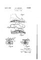
- Figure 1 is a side elevation of a shoe partly in section showing two forms of my adjustable support for the arch and ball of the foot respectively.
- Figure 2 is top view of the same partly broken away. 4
- Figure'3 is a cross-sectional side view of a shoe showing the form of adjustable support preferable for supporting the arch.
- Figure 4 is an enlarged sectional view of my adjuster taken on the line 44 of Figure 3.
- Fi ure 5 is a sectional view of my adjuster provided with a spiral spring.
- This adjusting member A which ts into a hole made in the sole or bottom of the shoe, usuall below the arch, is composed of a screw 18 havlng a head 19 which fits over said spring lece 14 and at the other end of said screw is a slot 20 to receive a screw driver.
- An outer casing or skirt 21 threads on this screw 18, which sln'rt has a flange 22 at the top.
- a plug 23 screws into the lower portion of the skirt to keep water and dirt out.
- a supporting plate 24 extends from the front of the heel portion of the shoe to the sole so that it bridges the arch of the foot. This plate 24 is flat and preferably made of metal as it must by sufliciently stifl to support the weight of the erson'using it.
- a ho e is provided in this supporting plate 24 and the skirt 21 extends through sa1d hole so that the under ed e of its flange 22 rests on said plate 24. en it is desired to adjust the support a screw driver is inserted in the slot 20 and the screw 18 is thereby turned to move it u wardly or downwardly as desired. If the arc requires greater or higher support the screw is moved upwar whereas if less su port is desired it is moved downwardly. 0 course, it will be understood that as many adjusters may be used as are necessary by merely providing more holes irti1 the spring piece 14 and in the sole of the s oe.
- spiral spring 30 is more especially adapted for use when it is desired to support the ball of the foot.
- a screw 35 is provided with a flange or shoulder 36, and a slot 39 at the outer end.
- a metal backer 37 is fastened under the inner sole.
- One end 31 of the spiral spring 30 is fastened to this ,1
- a foot support for a -'hoe' which has a hole in the outer sole, comprisin a curved backer under the inner sole of t eshoe, a spring piece under said backer and attached at one end to said backer and havingahole therein in alinement with said hole in the outer sole, a supporting plate be1ovsaidspring piece having a hole therein in alininent with said other holes, and an adjusting member embodying screwe on said screw, said screw having a portion adjacent the top extending beyond the body of the screw on which the'under side of said spring piece contacts, said sln'rt having a flange at its top ortion which flange rests 101::e the uppersur ace of said support- 1ng p a DR. WALTER E. COPITHORN.
Landscapes
- Health & Medical Sciences (AREA)
- Epidemiology (AREA)
- General Health & Medical Sciences (AREA)
- Public Health (AREA)
- Footwear And Its Accessory, Manufacturing Method And Apparatuses (AREA)
Description
April 12, 1932. w E COP|THQRN 1,853,550
ADJUSTABLE FOOT SUPPORT Filed Sept. 14, 1929 fl iifeiiioi' WM 6.
atkoz-zngy Patented Apr. 12, 1932 UNITED STATES wanna a corrrnoan, or NA'HQK, mucnusm'rs ADJUSTABLE I'OO'I' SUPPORT Application filed September 14, 1939. Serial Io. 898,508.
each person. Another object has been tomake this support comfortable and resilient for the wearer.
With the above and other objects in view which will more readily appear as the nature of the invention is better understood, the same consists in the novel construction, combina- 29 tion and arrangement of parts hereinafter more fully described, claimed and illustrate in the accompanying drawings.
In the drawings: Figure 1 is a side elevation of a shoe partly in section showing two forms of my adjustable support for the arch and ball of the foot respectively.
Figure 2 is top view of the same partly broken away. 4
Figure'3 is a cross-sectional side view of a shoe showing the form of adjustable support preferable for supporting the arch.
Figure 4 is an enlarged sectional view of my adjuster taken on the line 44 of Figure 3.
Fi ure 5 is a sectional view of my adjuster provided with a spiral spring.
As illustrated my foot support when used to support the arch consists of an inner sole 12, which fits inside the shoe and extends from the heel to a point beyondthe arch. Attached and fitted to the under side of which inner sole is a curved arch piece or backer 13 made of metal or other strongmaterial. Beneath 45 the arch piece 13 is a spring metal piece 14 which is fastened at one end to the heel portion of the inner sole 12 by rivets 15 which also pass through the arch piece 13. This spring piece 14 is so shaped that there is a 50 space 16 between its middle portion and the arch piece 13. The front end of this spring piece 14 is preferably not fastened, so that it in said spring piece 14 in which hole the ad- -'justing member A is held at its to portion.
This adjusting member A, which ts into a hole made in the sole or bottom of the shoe, usuall below the arch, is composed of a screw 18 havlng a head 19 which fits over said spring lece 14 and at the other end of said screw is a slot 20 to receive a screw driver.
An outer casing or skirt 21 threads on this screw 18, which sln'rt has a flange 22 at the top. A plug 23 screws into the lower portion of the skirt to keep water and dirt out. A supporting plate 24 extends from the front of the heel portion of the shoe to the sole so that it bridges the arch of the foot. This plate 24 is flat and preferably made of metal as it must by sufliciently stifl to support the weight of the erson'using it.
A ho e is provided in this supporting plate 24 and the skirt 21 extends through sa1d hole so that the under ed e of its flange 22 rests on said plate 24. en it is desired to adjust the support a screw driver is inserted in the slot 20 and the screw 18 is thereby turned to move it u wardly or downwardly as desired. If the arc requires greater or higher support the screw is moved upwar whereas if less su port is desired it is moved downwardly. 0 course, it will be understood that as many adjusters may be used as are necessary by merely providing more holes irti1 the spring piece 14 and in the sole of the s oe.
In the event that my adjustable foot support is inserted in the manufacture of the shoe the usual inner sole in the shoe takes the place of the inner sole 12.
I have shown a modification of m invention whereby a spiral spring may used. This spiral spring 30 is more especially adapted for use when it is desired to support the ball of the foot. In this event a screw 35 is provided with a flange or shoulder 36, and a slot 39 at the outer end. Under the inner sole a metal backer 37 is fastened. One end 31 of the spiral spring 30 is fastened to this ,1
backer 37 while the other end 32 fits into a hole made in the side of the screw. Askirt 38, interiorly screw threaded, having a shoulder 38a, is fitted into the sole of the shoe, in which skirt the screw 35 is threaded. As the,screw 35 is moved upwardly b screwing, its flange 36 compresses the spin spring 30, exerting a force upwardly on the metal backer 37 thereby raisin it, and, of course as the screw 35 is moved ownwardly the opposite effect is produced. The cap 40 fits into the screw 35 to keep the dirt out.
While a specific embodiment of the invention has been illustrated-and described, the invention is not to be considered as limited to the particular combination'and arrangement of parts as above described, except as limited in scope by the appended I claim:
A foot support for a -'hoe' which has a hole in the outer sole, comprisin a curved backer under the inner sole of t eshoe, a spring piece under said backer and attached at one end to said backer and havingahole therein in alinement with said hole in the outer sole, a supporting plate be1ovsaidspring piece having a hole therein in alininent with said other holes, and an adjusting member embodying screwe on said screw, said screw having a portion adjacent the top extending beyond the body of the screw on which the'under side of said spring piece contacts, said sln'rt having a flange at its top ortion which flange rests 101::e the uppersur ace of said support- 1ng p a DR. WALTER E. COPITHORN.
claini.
League a screw and a: screw-threaded skirt a
Priority Applications (1)
| Application Number | Priority Date | Filing Date | Title |
|---|---|---|---|
| US392508A US1853550A (en) | 1929-09-14 | 1929-09-14 | Adjustable foot support |
Applications Claiming Priority (1)
| Application Number | Priority Date | Filing Date | Title |
|---|---|---|---|
| US392508A US1853550A (en) | 1929-09-14 | 1929-09-14 | Adjustable foot support |
Publications (1)
| Publication Number | Publication Date |
|---|---|
| US1853550A true US1853550A (en) | 1932-04-12 |
Family
ID=23550874
Family Applications (1)
| Application Number | Title | Priority Date | Filing Date |
|---|---|---|---|
| US392508A Expired - Lifetime US1853550A (en) | 1929-09-14 | 1929-09-14 | Adjustable foot support |
Country Status (1)
| Country | Link |
|---|---|
| US (1) | US1853550A (en) |
Cited By (5)
| Publication number | Priority date | Publication date | Assignee | Title |
|---|---|---|---|---|
| US2899758A (en) * | 1959-08-18 | Adjustable orthopedic support | ||
| US3794037A (en) * | 1969-11-18 | 1974-02-26 | W Matteson | Adjustable arch support for a shoe |
| US6609314B1 (en) * | 2000-03-15 | 2003-08-26 | Benjamin B. Dubner | Mechanical interior shoe adjustment |
| US20080184594A1 (en) * | 2004-10-29 | 2008-08-07 | Stephan Ebeling | Shoe Sole With Pressure Massage Function |
| US20110289798A1 (en) * | 2009-01-23 | 2011-12-01 | Foot Balance Co., Ltd. | Functional shoe |
-
1929
- 1929-09-14 US US392508A patent/US1853550A/en not_active Expired - Lifetime
Cited By (5)
| Publication number | Priority date | Publication date | Assignee | Title |
|---|---|---|---|---|
| US2899758A (en) * | 1959-08-18 | Adjustable orthopedic support | ||
| US3794037A (en) * | 1969-11-18 | 1974-02-26 | W Matteson | Adjustable arch support for a shoe |
| US6609314B1 (en) * | 2000-03-15 | 2003-08-26 | Benjamin B. Dubner | Mechanical interior shoe adjustment |
| US20080184594A1 (en) * | 2004-10-29 | 2008-08-07 | Stephan Ebeling | Shoe Sole With Pressure Massage Function |
| US20110289798A1 (en) * | 2009-01-23 | 2011-12-01 | Foot Balance Co., Ltd. | Functional shoe |
Similar Documents
| Publication | Publication Date | Title |
|---|---|---|
| US1920112A (en) | Spring heel seat | |
| US3266177A (en) | Adjustable heel for shoes | |
| US2139885A (en) | Removable heel | |
| US2212613A (en) | Stature increasing shoe | |
| US2336632A (en) | Athletic shoe pad | |
| US1853550A (en) | Adjustable foot support | |
| US2212414A (en) | Adjustable height increasing shoe | |
| US1778089A (en) | Rubber-heel-attaching plate for shoes | |
| US2184209A (en) | Adjustable height increasing shoe | |
| US2309783A (en) | Cleat for use on athletic shoes | |
| US2215463A (en) | Shoe sole | |
| US1998624A (en) | Rubber heel | |
| US2464251A (en) | Rubber heel | |
| US2713731A (en) | Heel | |
| US2350362A (en) | Novel resilient heel construction | |
| US2188225A (en) | Shoe construction | |
| US1546245A (en) | Shoe-straightening insole and arch support | |
| US2760280A (en) | Lady's shoe heel | |
| US2257482A (en) | Shoe construction | |
| US2525658A (en) | Ankle coupling for paralytic feet | |
| US1952330A (en) | Heel | |
| US2072765A (en) | Sole | |
| US372435A (en) | Isidoe sommeepield | |
| US1782436A (en) | Heel-attaching means | |
| US2184210A (en) | Insertable adjustable height increasing elevator for shoes |