US1853547A - Jerk line break out pulley - Google Patents
Jerk line break out pulley Download PDFInfo
- Publication number
- US1853547A US1853547A US457563A US45756330A US1853547A US 1853547 A US1853547 A US 1853547A US 457563 A US457563 A US 457563A US 45756330 A US45756330 A US 45756330A US 1853547 A US1853547 A US 1853547A
- Authority
- US
- United States
- Prior art keywords
- ring
- lugs
- casing
- jerk
- jerk line
- Prior art date
- Legal status (The legal status is an assumption and is not a legal conclusion. Google has not performed a legal analysis and makes no representation as to the accuracy of the status listed.)
- Expired - Lifetime
Links
Images
Classifications
-
- E—FIXED CONSTRUCTIONS
- E21—EARTH DRILLING; MINING
- E21B—EARTH DRILLING, e.g. DEEP DRILLING; OBTAINING OIL, GAS, WATER, SOLUBLE OR MELTABLE MATERIALS OR A SLURRY OF MINERALS FROM WELLS
- E21B19/00—Handling rods, casings, tubes or the like outside the borehole, e.g. in the derrick; Apparatus for feeding the rods or cables
- E21B19/16—Connecting or disconnecting pipe couplings or joints
- E21B19/161—Connecting or disconnecting pipe couplings or joints using a wrench or a spinner adapted to engage a circular section of pipe
- E21B19/162—Connecting or disconnecting pipe couplings or joints using a wrench or a spinner adapted to engage a circular section of pipe cathead actuated
Definitions
- This invention relates to new and useful the inner face of which are formed the inimprovements .in well drilling devices, and clined "lugs 16. Disposed longitudinally particularly to devices for loosening and un-' through the casing 10, and through the memscrewing the joint-s of drill rods, pipes, and her 12 is a shaft 17 Mounted on the stem the like, in connection with rotary drillin portion 14, ofthe member 12, is acylindrical 5 i machinery.
- I member 18, having the intermediate periph- The principal object of the invention is to eral enlarged portion 19, in the outer face provide adevice which is known as a eat of which is formed the circumferential groove head, by means of which the joint loosening 20, in which is arranged to be wound the wrench may be properly operated, in one din jerk line cable or wire 21. Acrossthe groove so rection, and wherein the device automatically isarranged the bar 22 to which one end of releases itself at each operation of said said cable orwire 21 is secured, the other end wrench. of said cable extending outwardly through a' Another object is to provide a device of slot 22 formed in the side of the casing 10.
- Figure 3 is a vertical transverse sectional in and out of the path of the lugs 16, of the View on line 33 of Figure 1.
- Projecting Figure 4 is a vertical transverse sectional from the peripheral face of the grooved porview of the device, on the line 44 of F igtion of. the member 18 is a lug 29 which is 1 ure 1. adapted to engage, at times with a lug 30 4O
- 10 re resents acylindrical casthe casing-10.
- a member Disposed within the diametrically opposite inclined cam lugs the casing is a member, represented as a 31, with which the radiating lugs 32, carried terminal spool portion 13, arranged outwardwhereby to cause the movement of sald ring ly of the casing, and the stem portion 14, longitudinally within the casing, as will be which is disposed longitudinally and centralclearly understood from an inspection of the 5 ly within the casing.
- the inner end of the drawings whole by the numeral 12, and comprising the by the ring 23, are adapted to be engaged,
- spool portion is formed with a flange 15, on The otherend of the cable or wire 21 is 16 adapted to be connected with the wrench (not shown) which is used in unscrewing the drill rod, pipe, or the like sections.
- the shaft 17 is in constant rotation, but if the clutch blades 24 are not in engagement with the lugs 16, the member 18, and the ring 23 will not rotate.
- the lever 27 Upon rocking the lever 27, to slide the ring 23, whereby to project the free ends of the blades 24 so that they will be engaged by the lugs 16, the member'j18, and-said ring will be rotated, with the result that the cable or wire 21 will be wound on the'said member, within the groove 20, pulling on the wrench so that an unscrewing action is imparted to'a section of the drill rod;
- the parts 18 and 23 are adapted tomake one complete turn, in this pulling action on the wrench, when the lugs 32' will'engage with the inclined lugs, .31, with the result that the ring 23 will be moved longitudinally on the'member 18, in a direction to withdraw the clutch blades 24 outof the path of the lugs, 16, thus permitting the member 12 to continue to rotate, while the member 18 is brought to a stop by engagement ofits
- spool rotatable with the shaft andhavingan extension'sleeve, a jerk line drumrro-tatable on the sleeve, aicollar rotatableon the sleeve, blades.
- a jerk linedevice comprising ashaft, 'a
- spool on the shaft and rotatable therewith and having an extension sleeve on the shaft, a jerk line drum rotatable on the sleeve, said drum having longitudinally inclined channels therein, a ring rotatable on the sleeve and movable toward. and away from said drum, and blades pivotally carried by said ringslidable through said channels into, and out of clutching engagement with said spool, and means for moving said ring.
- a jerk line device comprising a casin a shaft in the casing, a spool on the shaft and rotatable-therewith, a sleeve on the spool extending into the casing, a flange on the spool overlying one end of said sleeve and having inwardly extending lugs,.a ring rotatable onthe other end of said sleeve, a jerk line drum rotatable on the sleeve between said fiange and said ring, said drumhaving' longitudinallinclined channels therein, blades pivotally carried by the ring for movement through said channels into and outof engagementwith saidlugs, means for manually moving the ringinone direction, and meanson
Description
April 12, 1932. c, w, BYRD 1,853,547
JERK LINE BREAK OUT PULLEY Filed May 50, 19 30 Patented Apr. 12, 1932 g UNITED STATES PATENT; FFICE.
CHARLES W. BYRD, F COBSICANA, TEXAS V JERK L nn BREAK our IPULLEY Applicationfiled May 30, 1930. Serial No. 457,563..
'This invention relates to new and useful the inner face of which are formed the inimprovements .in well drilling devices, and clined "lugs 16. Disposed longitudinally particularly to devices for loosening and un-' through the casing 10, and through the memscrewing the joint-s of drill rods, pipes, and her 12 is a shaft 17 Mounted on the stem the like, in connection with rotary drillin portion 14, ofthe member 12, is acylindrical 5 i machinery. I member 18, having the intermediate periph- The principal object of the invention is to eral enlarged portion 19, in the outer face provide adevice which is known as a eat of which is formed the circumferential groove head, by means of which the joint loosening 20, in which is arranged to be wound the wrench may be properly operated, in one din jerk line cable or wire 21. Acrossthe groove so rection, and wherein the device automatically isarranged the bar 22 to which one end of releases itself at each operation of said said cable orwire 21 is secured, the other end wrench. of said cable extending outwardly through a' Another object is to provide a device of slot 22 formed in the side of the casing 10.
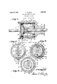
this character which is simple in construction, Mountedfor longitudinal slidable movement 05 and wherein the operating elements of the on one end of the member 18, is a peripheralclutch may be readily removed and replaced, 1y grooved ring 23, and pivotally supported without completely dismantling the entire on said ring are the clutch blades 24:, which device. are arranged to slide in the longitudinal A further object is to provide a device of grooves 25, formed in the member 18. Stop 7 this character wherein the winding drum of members 26 are disposed across these grooves the jerk line is prevented from spinning, at 25, to limit the movement of said blades, the the completion of its wrench pulling action. bottoms of said grooves inclining longitu- Other objects and advantages will be apdinally so that their deepest ends lie adjacent parent from the following description when the ring 23, while"theirshallowest ends-lie 7 5 taken in connectionv with the accompanying adjacent the other end of the member 18, as drawings. clearly seen inthe sectional view, Figure .1. In the drawings: Pivotally mounted in one end of the casing Figure 1 is a vertical longitudinal sectional is a'lever 27, the inner end of which is formed 30 view of a jerk line device, made in accordance with" a fork'28, having the ends of its furcaso with the present invention. tions engaged in the peripheral groove of Figure 2 is a vertical transverse central the ring 23, by means of which said ringmay sectional view through the device, on the line be movedv longitudinally on the member 18,
22 of Figure 1. to dispose the ends of the clutch blades 24 7 Figure 3 is a vertical transverse sectional in and out of the path of the lugs 16, of the View on line 33 of Figure 1. flange 15, of the spool portion 13. Projecting Figure 4 is a vertical transverse sectional from the peripheral face of the grooved porview of the device, on the line 44 of F igtion of. the member 18 is a lug 29 which is 1 ure 1. adapted to engage, at times with a lug 30 4O Referring particularly to the accompanyprojecting inwardly from'the inner face of v ing drawings, 10 re resents acylindrical casthe casing-10. Also carried by the inner ing which is provi ed with a removable clofaceof the casing adjacent the ring 23, are sure disk 11, in one end. Disposed within the diametrically opposite inclined cam lugs the casing is a member, represented as a 31, with which the radiating lugs 32, carried terminal spool portion 13, arranged outwardwhereby to cause the movement of sald ring ly of the casing, and the stem portion 14, longitudinally within the casing, as will be which is disposed longitudinally and centralclearly understood from an inspection of the 5 ly within the casing. The inner end of the drawings whole by the numeral 12, and comprising the by the ring 23, are adapted to be engaged,
spool portion is formed with a flange 15, on The otherend of the cable or wire 21 is 16 adapted to be connected with the wrench (not shown) which is used in unscrewing the drill rod, pipe, or the like sections.
In the operation of the device, the shaft 17 is in constant rotation, but if the clutch blades 24 are not in engagement with the lugs 16, the member 18, and the ring 23 will not rotate. Upon rocking the lever 27, to slide the ring 23, whereby to project the free ends of the blades 24 so that they will be engaged by the lugs 16, the member'j18, and-said ring will be rotated, with the result that the cable or wire 21 will be wound on the'said member, within the groove 20, pulling on the wrench so that an unscrewing action is imparted to'a section of the drill rod; The parts 18 and 23 are adapted tomake one complete turn, in this pulling action on the wrench, when the lugs 32' will'engage with the inclined lugs, .31, with the result that the ring 23 will be moved longitudinally on the'member 18, in a direction to withdraw the clutch blades 24 outof the path of the lugs, 16, thus permitting the member 12 to continue to rotate, while the member 18 is brought to a stop by engagement ofits lugs 29 with the lugs 80, of
th casing. It is understood thatthe wrench is swungto get a new grip on the drill rod section by any suitable means, as springs, or
byhand, but as this forms no part ofthe present invention, such is not illustatedr lpon the return movement of the wrench, the cable or wire 21- is pulled, whereby to unwind the latter from the member 18, which causes a retrograde rotation of such member, such rotation continuing. until the lug 29 again engages the lug 30, "which brings this rotation to an end. Upon again'swinging the lever 27, the wire 21 will be wound on the ,member 18, and'the wrench given another movement'toimpart an unscrewing action on the. drillirod' section. This is continued until'the'drill rod sections have beencome pletely separated, or unscrewed sufficiently to permit the operator to complete the opera 'tion by handor machinery.
spool rotatable with the shaft andhavingan extension'sleeve, a jerk line drumrro-tatable on the sleeve, aicollar rotatableon the sleeve, blades. movably carried by the collar and slidable through said drum into and outof clutching engagement with saidspool, means for moving the collar in one direction to engagethe blades'with the spool, and means for automatically'moving the collar in the opposite direction to disengage said blades.
2. A jerk linedevice comprising ashaft, 'a
spool on the shaft and rotatable therewith and having an extension sleeve on the shaft, a jerk line drum rotatable on the sleeve, said drum having longitudinally inclined channels therein, a ring rotatable on the sleeve and movable toward. and away from said drum, and blades pivotally carried by said ringslidable through said channels into, and out of clutching engagement with said spool, and means for moving said ring.
3. A jerk line device comprising a casin a shaft in the casing, a spool on the shaft and rotatable-therewith, a sleeve on the spool extending into the casing, a flange on the spool overlying one end of said sleeve and having inwardly extending lugs,.a ring rotatable onthe other end of said sleeve, a jerk line drum rotatable on the sleeve between said fiange and said ring, said drumhaving' longitudinallinclined channels therein, blades pivotally carried by the ring for movement through said channels into and outof engagementwith saidlugs, means for manually moving the ringinone direction, and meanson
Priority Applications (1)
| Application Number | Priority Date | Filing Date | Title |
|---|---|---|---|
| US457563A US1853547A (en) | 1930-05-30 | 1930-05-30 | Jerk line break out pulley |
Applications Claiming Priority (1)
| Application Number | Priority Date | Filing Date | Title |
|---|---|---|---|
| US457563A US1853547A (en) | 1930-05-30 | 1930-05-30 | Jerk line break out pulley |
Publications (1)
| Publication Number | Publication Date |
|---|---|
| US1853547A true US1853547A (en) | 1932-04-12 |
Family
ID=23817215
Family Applications (1)
| Application Number | Title | Priority Date | Filing Date |
|---|---|---|---|
| US457563A Expired - Lifetime US1853547A (en) | 1930-05-30 | 1930-05-30 | Jerk line break out pulley |
Country Status (1)
| Country | Link |
|---|---|
| US (1) | US1853547A (en) |
Cited By (1)
| Publication number | Priority date | Publication date | Assignee | Title |
|---|---|---|---|---|
| US2481161A (en) * | 1944-04-22 | 1949-09-06 | John H Schreiber | Joint breaker and cathead |
-
1930
- 1930-05-30 US US457563A patent/US1853547A/en not_active Expired - Lifetime
Cited By (1)
| Publication number | Priority date | Publication date | Assignee | Title |
|---|---|---|---|---|
| US2481161A (en) * | 1944-04-22 | 1949-09-06 | John H Schreiber | Joint breaker and cathead |
Similar Documents
| Publication | Publication Date | Title |
|---|---|---|
| US1621947A (en) | Casing puller | |
| US1492466A (en) | Pipe-gripping device | |
| US2192484A (en) | Pipe coupler | |
| US1853547A (en) | Jerk line break out pulley | |
| US2024891A (en) | Pinion puller | |
| US1891832A (en) | Elevating and rotating device | |
| US2012280A (en) | Chuck mechanism | |
| US2295932A (en) | Cathead | |
| US2117050A (en) | Inside casing cutter | |
| US1692302A (en) | Well-capping device and controlling head | |
| US2124129A (en) | Joint breaker | |
| US1702822A (en) | Tongs | |
| US1637383A (en) | Drill-stem clamp | |
| US2056496A (en) | Jar | |
| US2217238A (en) | Sucker rod wrench | |
| US1559874A (en) | Tool joint | |
| US1764291A (en) | Drill chuck | |
| US1627842A (en) | Device for unscrewing and withdrawing pipe | |
| US2144810A (en) | Adjusting device for jars | |
| USRE18789E (en) | Cathead | |
| US2001057A (en) | Drill boxing | |
| US1735272A (en) | Boiler-tube puller | |
| US1785590A (en) | Automatic resetting spear | |
| US1672321A (en) | Rotary jar | |
| US2122602A (en) | Rotary automatic latch trip socket |