US1853532A - Golf club - Google Patents
Golf club Download PDFInfo
- Publication number
- US1853532A US1853532A US388985A US38898529A US1853532A US 1853532 A US1853532 A US 1853532A US 388985 A US388985 A US 388985A US 38898529 A US38898529 A US 38898529A US 1853532 A US1853532 A US 1853532A
- Authority
- US
- United States
- Prior art keywords
- shaft
- sections
- section
- golf club
- portions
- Prior art date
- Legal status (The legal status is an assumption and is not a legal conclusion. Google has not performed a legal analysis and makes no representation as to the accuracy of the status listed.)
- Expired - Lifetime
Links
- 238000010276 construction Methods 0.000 description 4
- 244000141359 Malus pumila Species 0.000 description 2
- 239000002131 composite material Substances 0.000 description 2
- 230000000694 effects Effects 0.000 description 2
- 239000000463 material Substances 0.000 description 2
- 239000002184 metal Substances 0.000 description 2
- 238000000034 method Methods 0.000 description 2
- 239000002023 wood Substances 0.000 description 2
- 244000046052 Phaseolus vulgaris Species 0.000 description 1
- 235000010627 Phaseolus vulgaris Nutrition 0.000 description 1
- 239000000853 adhesive Substances 0.000 description 1
- 230000001070 adhesive effect Effects 0.000 description 1
- 238000004519 manufacturing process Methods 0.000 description 1
- 230000008439 repair process Effects 0.000 description 1
- 239000007787 solid Substances 0.000 description 1
Images

Classifications
-
- A—HUMAN NECESSITIES
- A63—SPORTS; GAMES; AMUSEMENTS
- A63B—APPARATUS FOR PHYSICAL TRAINING, GYMNASTICS, SWIMMING, CLIMBING, OR FENCING; BALL GAMES; TRAINING EQUIPMENT
- A63B53/00—Golf clubs
- A63B53/10—Non-metallic shafts
-
- A—HUMAN NECESSITIES
- A63—SPORTS; GAMES; AMUSEMENTS
- A63B—APPARATUS FOR PHYSICAL TRAINING, GYMNASTICS, SWIMMING, CLIMBING, OR FENCING; BALL GAMES; TRAINING EQUIPMENT
- A63B60/00—Details or accessories of golf clubs, bats, rackets or the like
-
- A—HUMAN NECESSITIES
- A63—SPORTS; GAMES; AMUSEMENTS
- A63B—APPARATUS FOR PHYSICAL TRAINING, GYMNASTICS, SWIMMING, CLIMBING, OR FENCING; BALL GAMES; TRAINING EQUIPMENT
- A63B60/00—Details or accessories of golf clubs, bats, rackets or the like
- A63B60/06—Handles
-
- A—HUMAN NECESSITIES
- A63—SPORTS; GAMES; AMUSEMENTS
- A63B—APPARATUS FOR PHYSICAL TRAINING, GYMNASTICS, SWIMMING, CLIMBING, OR FENCING; BALL GAMES; TRAINING EQUIPMENT
- A63B60/00—Details or accessories of golf clubs, bats, rackets or the like
- A63B60/06—Handles
- A63B60/08—Handles characterised by the material
-
- A—HUMAN NECESSITIES
- A63—SPORTS; GAMES; AMUSEMENTS
- A63B—APPARATUS FOR PHYSICAL TRAINING, GYMNASTICS, SWIMMING, CLIMBING, OR FENCING; BALL GAMES; TRAINING EQUIPMENT
- A63B60/00—Details or accessories of golf clubs, bats, rackets or the like
- A63B60/06—Handles
- A63B60/10—Handles with means for indicating correct holding positions
Definitions
- My invention relates to the construction of shafts such as are utilized in golf clubs and the like.
- a further object of my invention is to provide a shaft so constructed that it will keep its shape and form without warping or buckling with change of weather conditions.
- a further obj ect of my invention is to provide a shaft construction of such a nature'v that the shaft is manufactured and assembled with a greater ease and economy than has been possible with shafts heretofore.
- FIG. 1 is an elevational view of a golf club employing a shaft constructed in accordance with my invention.
- Figure 2 is a section through the shaft il- ,n lustrated in Fig. 1 along the lines 2 2 there- Figures 3 to 5 inclusive,villustrate other shaft sections and methods of constructing a l shaft in accordance with my invention.
- Figure 6 is a cross section thru another i form of shaft.
- Figure 7 is a. side elevation of a form of shaft which I employ.
- Figure 8 is a cross section through the 5 shaft illustrated in Fig. 7 along the line 8-.8
- my invention may be generally characterized as comprising the construction of a shaft of segmental portions, the portions being so formed as to provide interlocking ⁇ surfaces which increase and impart certain desired features.
- Vtheshaft is preferably formed of substantially identical portions8 and 9. These portions I have conveniently formed of a suitable material such as metal.
- the shaft 7 does not comprise merely a hollow tube or 85 solid rod as has been utilized with shafts heretofore, but includes portions 8 and 9 which are.k provided with interlocking surfaces.
- portions 8 and 9 which are.k provided with interlocking surfaces.
- extensions 11 and 12 which are formed on the respective portions 8 and 9 are curved back upon the portions to provide what may be termed a diametral base to the portions;
- the exten-sions are provided with means for A effecting an interlock between them.
- My invention is also useful in providing nl Wooden shafts for those clubs in Which it is believed that Wood is the most satisfactory material for the shaft.
- I have expediently formed the shaft of a plu- Yrality of sections 21.
- I am enabled to effect a greater economy in the manufacture and assembly of the shaft, in that smaller portions of Wood need be utilized to build up the shaftV
- the several sections have been glued together, is securely joined together not only by the adhesive used but by the interlocking vof the several projections with the recesses. Y Further, by providing the interlockthe assembly of the shaft from the several sections is facilitated.
- QI also prefer to form the shaft of the sections With the grains of therWood running i'nsubstantially different directions, and with the interlocking of the several sections together, a greater resistance isV thus provided Vin the shaft for those changes which are occasioned upon yWeather or climatic variations.
- the metal portions' 8 and 9 are provided With interengaging members 27 and y28 respectively. These are adapted to be engaged to provide a' Ycomposite shaft structure which I have found is most usefulY and desirable Where certain characteristics' are desired as in the game of golf.
- the joining ofthe portions is conveniently done With aY rivet V29 extending thru the aperture 26.
- a bolt or other engaging means may be employed so that the shaft structure may be disassembledfor repairs or replacement.
- a iirst shaft section In a composite shaft, a iirst shaft section, a second shaft section substantially identical in form With said first section, and means on each of said sections for substantially locking said sections together against only relative transverse sliding movement.
- a first section having 'a recess formed therein, and a second section substantially identical With said first section and having a projection thereon, said project-ion being formed to engage said recess to provide an interlock between said sections substantially to resist torsion and to prevent ransverse sliding of one section on the second section.
- a golf club having a shaft, a rst shaft section, a second shaft section, a projection formed upon said first section, the second section having a recess to receive said projection Twhereby relative transverse movement ofthe sections is prevented, and means for securing the shaft sections together to prevent only the relative transverse movement.
- a shaft consisting of a first shaft section, a second shaft section, said shaft sections each including a tongue and groove portion adapted to cooperate with a groove or tongue on another section to restrain the sections against relative transverse sliding movement, but permitting relative longitudinal sliding movement.
Landscapes
- Health & Medical Sciences (AREA)
- General Health & Medical Sciences (AREA)
- Physical Education & Sports Medicine (AREA)
- Golf Clubs (AREA)
Description
P. F. APFEL April l2, 1932.
EE F5 L. I IN V EN TOR Phil/'lo F. Apfz/ A TTORNEY April 12, 1932. p. F APFEL 1,853,532
GOLF CLUB Filed Aug. 28. 1929 2 Sheets-Sheet 2 FIE E INVENToR. Dh/ICD E 4,02%/
Patented Apr. 12, 1932i` 'rares PHILIP F. APFEL, iOEk SEATTLE, WASHINGTON GOLF CLUB Application filed August 28, 1929. Serial No. 388,985.
My invention relates to the construction of shafts such as are utilized in golf clubs and the like.
lt is known that in such articles as golfclubs the provision of a shaft having relatively great flexibility or whip is extremely desirable inasmuch as a greater distance is obtainable with a club having such a shaft. 'In methods of construction used heretofore the whip obtainable is limited because of the mechanical strength which has been found necessary, in a given size, for a reasonable durability of the shaft. It is therefore an object of my invention to provide a shaft in which the flexibility, the strength, and the durability are increased without increasing substantially either size or weight.
A further object of my invention is to provide a shaft so constructed that it will keep its shape and form without warping or buckling with change of weather conditions.
A further obj ect of my invention is to provide a shaft construction of such a nature'v that the shaft is manufactured and assembled with a greater ease and economy than has been possible with shafts heretofore.
My invention possesses other advantageous features some of which with the foregoing will be set forth in the following description.
i It is to be understood that the invention as defined by the claims is to be accorded a range of equivalents consistent with the state of the prior art.
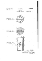
In the drawings "u Figure 1 is an elevational view of a golf club employing a shaft constructed in accordance with my invention.
Figure 2 is a section through the shaft il- ,n lustrated in Fig. 1 along the lines 2 2 there- Figures 3 to 5 inclusive,villustrate other shaft sections and methods of constructing a l shaft in accordance with my invention. Figure 6 is a cross section thru another i form of shaft.
Figure 7 is a. side elevation of a form of shaft which I employ.
Figure 8 is a cross section through the 5 shaft illustrated in Fig. 7 along the line 8-.8
thereof.
Briefly, my invention may be generally characterized as comprising the construction of a shaft of segmental portions, the portions being so formed as to provide interlocking` surfaces which increase and impart certain desired features.
In that form` of my invention which is parV- ticularly shown in Figs., 1 and 2, a head@ is al'iXed toa shaft 7 in any convenientmannen As is shown in Fig. l2, Vtheshaft is preferably formed of substantially identical portions8 and 9. These portions I have conveniently formed of a suitable material such as metal.
It iste benoted, however, that the shaft 7 does not comprise merely a hollow tube or 85 solid rod as has been utilized with shafts heretofore, but includes portions 8 and 9 which are.k provided with interlocking surfaces. Thus extensions 11 and 12 which are formed on the respective portions 8 and 9 are curved back upon the portions to provide what may be termed a diametral base to the portions; The exten-sions are provided with means for A effecting an interlock between them. To effect this interlock conveniently, I form a substantially symmetrical eye 13 upon each of the extensions which are so adapted that theycan be interengaged to lock` the respective portions 8 and 9 together. i
I have found thatA the flexibility and whip 8( of the shaft is materially enhanced if the extensions 11 and 12 are positioned in such a manner with. respect to the face 16 of the head 6 that they are substantially parallel thereto. This provides for an increased degree of exibility since the respective sections can slide along each other to a certainV extent while other movements than this as a transverse sliding movement aresubstantially prohibited A VThe sections are conveniently maintained in position with respect to each other by the wrappings and grip portion usually provided upon the shaft. Thus the wrapping indicated at 17 near` thel head of the club serves to secure the sections together :at this point while the wrappings 18 andthe grip portion 19 secure the sections at the handle end ofthe club. i
My invention is also useful in providing nl Wooden shafts for those clubs in Which it is believed that Wood is the most satisfactory material for the shaft. In this connection I have expediently formed the shaft of a plu- Yrality of sections 21. By providing a plurality of sections, I am enabled to effect a greater economy in the manufacture and assembly of the shaft, in that smaller portions of Wood need be utilized to build up the shaftV When the several sections have been glued together, is securely joined together not only by the adhesive used but by the interlocking vof the several projections with the recesses. Y Further, by providing the interlockthe assembly of the shaft from the several sections is facilitated.
QI also prefer to form the shaft of the sections With the grains of therWood running i'nsubstantially different directions, and with the interlocking of the several sections together, a greater resistance isV thus provided Vin the shaft for those changes which are occasioned upon yWeather or climatic variations.
In that form of my invention which is illustrated in Figures 6 to 8 inclusive the shaft 7 Vis assembled sothat the movement of the component parts of the shaft is provided for. Thus in that form shown particularly in Figure 8 theshaft sections 21 are joined together conveniently as by a bolt Qavvhich extends thru an aperture 26. This aperture is of a Width to receive the bolt and of a length suiiicient to allow for a degree of sliding of the faces relative to each other. This aids also in assembling the shafts and in securing the sections together.
In that form shown in Figure 6 the metal portions' 8 and 9 are provided With interengaging members 27 and y28 respectively. These are adapted to be engaged to provide a' Ycomposite shaft structure which I have found is most usefulY and desirable Where certain characteristics' are desired as in the game of golf. The joining ofthe portions is conveniently done With aY rivet V29 extending thru the aperture 26. When desired a bolt or other engaging means may be employed so that the shaft structure may be disassembledfor repairs or replacement. In
prising a shaftjoined to said head, said shaft being formed of substantially identical sections, and means onone of said sections for providing an interlock With another of the sections whereby the sections are substantial- `ly secured against relative transverse movement.
3. In a composite shaft, a iirst shaft section, a second shaft section substantially identical in form With said first section, and means on each of said sections for substantially locking said sections together against only relative transverse sliding movement.
4. In a composite shaft, a first section having 'a recess formed therein, and a second section substantially identical With said first section and having a projection thereon, said project-ion being formed to engage said recess to provide an interlock between said sections substantially to resist torsion and to prevent ransverse sliding of one section on the second section. Y
5. In a golf club having a shaft, a rst shaft section, a second shaft section, a projection formed upon said first section, the second section having a recess to receive said projection Twhereby relative transverse movement ofthe sections is prevented, and means for securing the shaft sections together to prevent only the relative transverse movement.
6. Ina golf club having a shaft, a first shaft section, a second shaft section, and means for interlocking said sections together, said means extending substantially entirely throughout the length of said sections so that relative transverse movement of the sections is prevented While relative sliding movement substantially can occur.
7. Ina golf club, a shaft consisting of a first shaft section, a second shaft section, said shaft sections each including a tongue and groove portion adapted to cooperate with a groove or tongue on another section to restrain the sections against relative transverse sliding movement, but permitting relative longitudinal sliding movement.
In testimony whereof, I have hereunto set my hand.
PHILIP F. APFEL.
this connection such a feature'as disassembly isadvantageous since various shaft portions of different characteristics may be assembled y to'secure a shaft havior in use.
Iclaim: l. A golf club including having al very definite bean head and com-
Priority Applications (1)
| Application Number | Priority Date | Filing Date | Title |
|---|---|---|---|
| US388985A US1853532A (en) | 1929-08-28 | 1929-08-28 | Golf club |
Applications Claiming Priority (1)
| Application Number | Priority Date | Filing Date | Title |
|---|---|---|---|
| US388985A US1853532A (en) | 1929-08-28 | 1929-08-28 | Golf club |
Publications (1)
| Publication Number | Publication Date |
|---|---|
| US1853532A true US1853532A (en) | 1932-04-12 |
Family
ID=23536366
Family Applications (1)
| Application Number | Title | Priority Date | Filing Date |
|---|---|---|---|
| US388985A Expired - Lifetime US1853532A (en) | 1929-08-28 | 1929-08-28 | Golf club |
Country Status (1)
| Country | Link |
|---|---|
| US (1) | US1853532A (en) |
Cited By (1)
| Publication number | Priority date | Publication date | Assignee | Title |
|---|---|---|---|---|
| US2878021A (en) * | 1955-08-12 | 1959-03-17 | Lippert Edward John | Bowling pin |
-
1929
- 1929-08-28 US US388985A patent/US1853532A/en not_active Expired - Lifetime
Cited By (1)
| Publication number | Priority date | Publication date | Assignee | Title |
|---|---|---|---|---|
| US2878021A (en) * | 1955-08-12 | 1959-03-17 | Lippert Edward John | Bowling pin |
Similar Documents
| Publication | Publication Date | Title |
|---|---|---|
| US1677099A (en) | Golf club | |
| US1549803A (en) | Ball bat | |
| US3265401A (en) | Reinforcement for a pole | |
| US1840183A (en) | Golf bag construction | |
| US1853532A (en) | Golf club | |
| US2457177A (en) | Golf club | |
| US2360240A (en) | Ski stick | |
| US1508286A (en) | Racket | |
| US1122159A (en) | Tennis-racket. | |
| US1345447A (en) | Rolling door | |
| US533272A (en) | Base-ball bat | |
| US1545879A (en) | Floor mat | |
| US2284214A (en) | Timber coupling | |
| US2036524A (en) | Device for use in sports | |
| US1530816A (en) | Ring-toss ring | |
| US1839811A (en) | Propeller | |
| US20130281225A1 (en) | Integrally Formed Golf Club | |
| US1648714A (en) | Shovel handle | |
| US1520108A (en) | Bowling pin | |
| US2878021A (en) | Bowling pin | |
| US330837A (en) | Pocket-rule | |
| US602258A (en) | Gael haupt | |
| US158689A (en) | Improvement in iron columns | |
| US433085A (en) | Metal boat | |
| US1921930A (en) | Golf club shaft |