US1853527A - Extension table - Google Patents
Extension table Download PDFInfo
- Publication number
- US1853527A US1853527A US552424A US55242431A US1853527A US 1853527 A US1853527 A US 1853527A US 552424 A US552424 A US 552424A US 55242431 A US55242431 A US 55242431A US 1853527 A US1853527 A US 1853527A
- Authority
- US
- United States
- Prior art keywords
- filler
- leaf
- members
- plane
- arm
- Prior art date
- Legal status (The legal status is an assumption and is not a legal conclusion. Google has not performed a legal analysis and makes no representation as to the accuracy of the status listed.)
- Expired - Lifetime
Links
Images

Classifications
-
- A—HUMAN NECESSITIES
- A47—FURNITURE; DOMESTIC ARTICLES OR APPLIANCES; COFFEE MILLS; SPICE MILLS; SUCTION CLEANERS IN GENERAL
- A47B—TABLES; DESKS; OFFICE FURNITURE; CABINETS; DRAWERS; GENERAL DETAILS OF FURNITURE
- A47B1/00—Extensible tables
- A47B1/02—Extensible tables with insertable leaves arranged in the centre and fixed frames
- A47B1/03—Extensible tables with insertable leaves arranged in the centre and fixed frames the leaves being foldable or revolvable
- A47B2001/035—Extensible tables with insertable leaves arranged in the centre and fixed frames the leaves being foldable or revolvable the extension leaves being unfoldable
Definitions
- My invention relates in general to extension tables and in particular to that type in which there is employed folding filler-leaves which may be adjusted in folded position for storage beneath the level of the table topmembers, or swung upwardly and unfolded into the same plane with the top-members to extend the service area of the table.
- An important advantage derived from the use of my improvements is that the same may be employed with any size of filler-leaf so that it is not necessary to keep different sizes of my device in stock.
- Another advantageous feature is that the device is directly attachable to the table top and independent of functioning with a bridge which may be dispensed with and it is double acting and can be employed with any type of base structure of the table. If the table'base is made with central legs, a pedestal or any other arrangement of base structure, so that the hinged end of the folding filler-leaf collides therewith, such hinged end will engage the same and be caused to raise up and thereby swing upwardly the filler-leaf support, which latter is so mounted that it cannot swing down below its normal level or position. This latter feature may be carried out' in either one of the two ways which I have herewith illustrated. Other advantages derived from the use of my improvements, will appear from the detailed description hereinafter given.
- Figure 1 shows a top plan view of an extension table embodying my improvements and with the table top-members slid apart for the reception of the folding filler-leaf which lies in stored position beneath the level of said top-members ready to be lifted up and unfolded into service position.
- Figure 2 is a view of a cross-section of the parts shown in Fig. 1, the plane of the section being indicated by the line 22, Fig. 1, and with the filler-leaf being shown in dotted lines in the position assumed thereby when it is partly unfolded.
- Figure 3 shows a sectional view on an en- 1931. Serial no. 552,424.
- Figure '4 is an enlarged sectional view of the difierent parts of the structure, with the filler-leaf unfolded into service position and with section being taken at right-angles to the section shown in'Fig. 3.
- Figure 5 shows a similar view to that in Fig. 2, but with the'section taken on a 'dif-' ferent plane which cuts the supporting bar of the filler-leaf.
- Figure 6 shows on a reduced scale a cross- 6 sectional view of the structure, with the bridge omitted so as to show how the hingedend of the filler-leaf is free to swing down, in its movements of folding and unfolding.
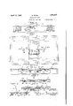
- Figure 7 is a top I plan view, similar to 70 that shown in Fig. 1, of a modified form of the filler-leaf supporting means.
- Figure 8 is across-sectional view of the structure shown in Fig. 7, the plane of the section being indicated by the line 88, 75 Fig. 7.
- Figures 9 and 10 are cross-sectional views of the structure shown in Fig. 7 but with the filler-leaf raised into unfolded position of service in cooperation wit-h the top-mem 80 bers, the two views being taken at right-angles to each other.
- 1 and 2 are sliding table top- 5 members movable toward and away, from each other by means of slides 3 and4, of member 1, moving on the guides 7 and 8, and slides 5 and 6, of member 2, moving on said guides, which guidesare supportedatthe'OO respective ends of the bridge 9, in the usual way.
- a folding fillerelea'f comprising two sections 10 and 11, hinged together at 12, is mounted on supporting means consisting'in 95 a bar or lever having a central part 13, with its ends angled or elbowed so as to provide oppositely projecting end-portions 14 and 15, respectively, all of the said parts 13, 14 and 15,
- brackets 18, 19, which are fas-' filler-leaf from dropping down.
- the inner arm 15 is disposed to one side of such line.
- I mayuse either the'projection or extension 20 on arm 14"at its end, which is arranged to strike against the underside of the top-member 2, and prevent the turning of the arm 14, in but one direction in order to keep arm 15 at its proper level, or a stop 'or' rest 21, consisting in a bracket secured to the underside of the top-member'and projecting beyond its edge so as to lie beneath the center part 13, and
- the filler-leaf is of large size and heavy, it is advisable to use a subj acent prop 22, consisting in.a U-shaped member having ltS'llPPGI' endpivoted at 23, to the brackets 18, and 19, in which the arm 15, is mounted.
- the prop is free to swing and when the fillerleaf-is unfolded, the prop will gravitate into vertical positon with-its lower free end rest- 1ng on the bridge 9-, and support the fillerleaf as shown in Figs. 3 and4.
- gAn upwardly inclined guide-24 is mounted on the slide 5, which is securedto and travels with the top-member 2, on which the fillerleaf is'mounted, and this guide is engaged by the free end of the filler-section 11, which rests on a fiat part25, of said guide when the The filler-leaf 10-11 is mounted- In order to filler sections are folded in stored position, as shown in Figs. 1, 2, 7 and 8.
- the filler-leaf is to be raised and unfolded into. the plane of the top-members, the operator grasps with his hand the free end of the then upper section 10, and lifts it and this causes the then under section 11, to slide from the flat part 25, thence up the incline part 24, and over the slide 5, as indicated in Fig. 2, in dotted-lines, and this movement continues until the sections assume the horizontal and rest with their ends across the slides and guides of the table, as indicated in Fig. 5.
- the operator seizes with his hand the outer free end of the section 10, lifts it and this causes the several parts to move in the reverse way from that just described and until the filler-sections close on each other in folded stored position,
- the supporting device for the filler-leaf is held against endwise movement by the bend 26, in arm 14, takingagainst one side i of bracket 17, and the pin 27 taking against the other side, see Fig. 1.
- the filler-leaf has. a slight sidewise movement on the supporting arm 15,'which movement is limited by the head 28, taking against one sideof the bracket 18, and the pin 29, on the arm taking against the other side.
- This lateral play of the fillerleaf is sufiicient to permit the functioning of the dowel pins 30 and their corresponding sockets 31, formed in the abutting edges of the filler-leaf and the top-members when the same are pushed together to extend the service area of the top. See Fig. 1.
- the supporting bar 13, 14 and 15* are duplicates of the parts 13, 14 and 15, of the other'form.
- the parts 13 and 14 are constructed the same as parts13 and 14- and form anextension of the part 15. It is whatI consider as a double-crank structure, with the severalparts disposed in the same plane.
- The. central part 15 is loosely mounted in the brackets 18 and 19*, secured upon the underside of the filler-leaf section 10, so that the filler may be swung on said part.
- the oppositely extending end portions 1 1 and 1 1- are mounted loosely in the re spective brackets 32and 33, which depend from the underside of the respective topmembers 1 and 2, and thus the filler supporting means is provided with bearings at its respective ends, instead of one end only, and a well balanced action is thereby obtained.
- the central part 15 which carries the swinging filler-leaf, is held up in normal horizontal position by means of the extension slide back and forth on said end portions, as-
- top-members are slid apartand then together, as will be understood from the several views shown in Figs. 7 to 10.
- Fig. 7 the folded-filler leaf is shown as in its lowermost position for storage, likewise the view in F 1g.
- FIG. 9 shows the filler-leaf opened into horizontal position and interposed between the top-memhers which'are closed against the filler.
- Fig. 10 the filler-leaf is stored away beneath the topnnembers which are closed together over the same.
- the table shown in the modification is of the leg type as indicated atthe corners at 34, and there is no bridge so there is nothing to obstruct the movement of the hinged ends of the filler-leaf sections in their downward sweep when being unfolded and also folded, as will be understood from Fig. 6.
- the supporting bar is prevented from being rocked in such a manner that the center part 15* cannot be lowered or dropped below normal position, it may be turned in the opposite direction so as to raise such part, and this will permit of the structure being used with a bridge.
- the freely swinging prop 22 is pivoted upon the back of the filler-deaf section 10, which lies uppermost when the sections are folded, so that the prop comes into action as the section 10 is lifted and swung into-horizontal position.
- the vertical position of the prop will then give a substantial support to the arbor on which the filler-leaf is mounted.
- An extension table having relatively adjustable table top-members, a folding fillerleaf adjustably mounted so that it may be moved into the plane of the top-members and also folded in stored position beneath said plane, means for adjustably supporting said filler-leaf consisting in an attaching part mounted upon one of said top-members, an arbor upon which said filler-leaf is mounted to swing on a horizontal axis, a connecting member between said arbor and attachingpart normally disposed below the level of' the said top-member transversely thereof,
- An extension table having relatively ad justable table top-members, a folding fillerleaf adjustably mounted so that it may be movedjinto the plane of the top-1nembersand also, folded in stored position beneath said plane, a supporting device for said fillerleaf consisting in a central part having at each end an elbowed arm extending at rightangles therefrom and in opposite directions, one of said arms being mounted upon one of said top-members and the other arm having.
- the arm which is mounted on said top-member being provided with means for preventing the arm' from turning but in one direction to prevent the. filler-leaf'carrying-arm from dropping down below its normal level.
- An extension table having relatively movable table top-members, a folding fillerleaf adjustably mounted so that itmay be moved into the plane of the top-members and also folded in stored position beneath said plane, a filler-leaf supporting bar having angled end portions projecting in opposite directions, one of said end portions being loosely mounted on one of said top-members substantially on the central longitudinal line thereof while the said-filler-leaf is mounted to swing on the other said end portion on an axis of motion disposed to one side of said central longitudinal line.
- An. extension table having relatively movable table top-members, a folding fillerleaf adjustably mounted so that it may be moved into the plane of said top-members and also folded instored position beneath said plane, a supporting device for said fillerleafv consisting in a centralpart having at each end a right-angled arm extending in opposite directions, one of said arms being mountedon one of said top-members and the other arm, having the filler-leaf mounted to swing thereon, and a rest or stop engaging said central-part to hold it against'downward movement.
- An extension-table having relatively movable table top-members, a folding fillerleaf adjustably mounted so that it may be moved into the plane of the top-members and also foldedin stored position beneath said plane, a filler-leaf supporting bar having elbowed end portions extending in opposite directions, one of said end portions being mounted on one of said top-members so as to rock thereon and permit the other said end portion to vertically reciprocate, means for preventing said latter end portion from dropping below its normal level, the said filler-leaf being mounted to swing on said latter end portion.
- An extension table havlng relatively movable table top-members, a folding fillerleaf adjustably mounted so that it may be moved into the plane of the top members and also folded in stored position beneath saidplane, a filler-leaf supporting bar having m angled end portions projecting in opposite di- 1 9 member to limit the rocking movement, the
- An extension table having relatively movable table top-members, a folding fillerleaf adjustably mounted so that it maybe moved into the plane of the top-members and also folded in stored position beneath said plane, a filler-leaf supporting device of substantial U-shape having its side members provided with outwardly and oppositely extending end portions, said end portlons being mounted on the respective top-members and thesaid filler-leaf being mounted to swing upon the middle-part of said supporting device, and means for preventing said middlepart of the support from dropping down below its normal position.
- An extension table having relatively movable table top-members, a folding fillerleaf adjustably mounted so that it may be moved into the plane of the top members and also folded in stored position beneath said plane, a filler-leaf supporting device of substantial U-shape having its'side parts provided with outwardly and oppositely extending end-portions, said end portions being loosely mounted on said respective topmembers so as to rock thereon and the said 'ller-leaf being mounted to swing on the middle-part of said device, and each end portion having means for preventing it from turning in but one direction.
- An extension cable having relatively movable table top-members, a folding fillerleaf composed of two sections hinged together and adjustably mounted so that they may be moved into the plane of the top-members and also folded in stored position beneath said plane, afiller-leaf supporting-bar secured to the underside of one of said top-members and projecting beyond the inner edge thereof, said filler-leaf being mounted to swing on said projecting part of the bar, and a freely swinging prop pivoted to the filler section which lies uppermost when folded and adapt- I ed to gravitate into vertical position when said sections are unfolded into horizontal position, and a fixed part for the bottom of said prop to rest on when in vertical position.
Description
April 12, 1932. M. WURM EXTENSION TABLE Filed July 22, 1931 2 Sheets- Sheet 2 Fad INVENTOR /fl Wax fi ar/zz v ATTORNEY Patented Apr. 12, 1932 "so srarus MAX WURM, or DETROIT, MICHIGAN EXTENSION TABLE Application filed July 22,
My invention relates in general to extension tables and in particular to that type in which there is employed folding filler-leaves which may be adjusted in folded position for storage beneath the level of the table topmembers, or swung upwardly and unfolded into the same plane with the top-members to extend the service area of the table.
An important advantage derived from the use of my improvements is that the same may be employed with any size of filler-leaf so that it is not necessary to keep different sizes of my device in stock. Another advantageous feature is that the device is directly attachable to the table top and independent of functioning with a bridge which may be dispensed with and it is double acting and can be employed with any type of base structure of the table. If the table'base is made with central legs, a pedestal or any other arrangement of base structure, so that the hinged end of the folding filler-leaf collides therewith, such hinged end will engage the same and be caused to raise up and thereby swing upwardly the filler-leaf support, which latter is so mounted that it cannot swing down below its normal level or position. This latter feature may be carried out' in either one of the two ways which I have herewith illustrated. Other advantages derived from the use of my improvements, will appear from the detailed description hereinafter given.
I have illustrated types of my improve ments in the accompanying drawings, wherein:
Figure 1 shows a top plan view of an extension table embodying my improvements and with the table top-members slid apart for the reception of the folding filler-leaf which lies in stored position beneath the level of said top-members ready to be lifted up and unfolded into service position.
Figure 2 is a view of a cross-section of the parts shown in Fig. 1, the plane of the section being indicated by the line 22, Fig. 1, and with the filler-leaf being shown in dotted lines in the position assumed thereby when it is partly unfolded.
, Figure 3 shows a sectional view on an en- 1931. Serial no. 552,424.
la'rged scale of the supporting device of the filler-leaf and the swinging prop, in the positionsassumed thereby when the filler-leaf is unfolded into the plane of the top-memers.
Figure '4 is an enlarged sectional view of the difierent parts of the structure, with the filler-leaf unfolded into service position and with section being taken at right-angles to the section shown in'Fig. 3.
Figure 5 shows a similar view to that in Fig. 2, but with the'section taken on a 'dif-' ferent plane which cuts the supporting bar of the filler-leaf.
Figure 6 shows on a reduced scale a cross- 6 sectional view of the structure, with the bridge omitted so as to show how the hingedend of the filler-leaf is free to swing down, in its movements of folding and unfolding.
Figure 7 is a top I plan view, similar to 70 that shown in Fig. 1, of a modified form of the filler-leaf supporting means.
Figure 8 is across-sectional view of the structure shown in Fig. 7, the plane of the section being indicated by the line 88, 75 Fig. 7. I
Figures 9 and 10 are cross-sectional views of the structure shown in Fig. 7 but with the filler-leaf raised into unfolded position of service in cooperation wit-h the top-mem 80 bers, the two views being taken at right-angles to each other.
Referring to the drawings, in which like numerals of reference designate like parts throughout, 1 and 2, are sliding table top- 5 members movable toward and away, from each other by means of slides 3 and4, of member 1, moving on the guides 7 and 8, and slides 5 and 6, of member 2, moving on said guides, which guidesare supportedatthe'OO respective ends of the bridge 9, in the usual way.
A folding fillerelea'f comprising two sections 10 and 11, hinged together at 12, is mounted on supporting means consisting'in 95 a bar or lever having a central part 13, with its ends angled or elbowed so as to provide oppositely projecting end-portions 14 and 15, respectively, all of the said parts 13, 14 and 15,
are shown as being disposed in a common by means of brackets 18, 19, which are fas-' filler-leaf from dropping down.
tened to the back of the filler section 10, and while the outer arm 14 is disposed substantially on the central longitudinal line of the top-member 2, the inner arm 15,is disposed to one side of such line. prevent the. filler carryingearm 15, from dropping below its normal level, I mayuse either the'projection or extension 20 on arm 14"at its end, which is arranged to strike against the underside of the top-member 2, and prevent the turning of the arm 14, in but one direction in order to keep arm 15 at its proper level, or a stop 'or' rest 21, consisting in a bracket secured to the underside of the top-member'and projecting beyond its edge so as to lie beneath the center part 13, and
" holdit in horizontal position and keep it from dropping. down. The bracket 21 is notched at 35 for receiving the part 13. 'This arrangementserves to sustain the filler carrying. arm 15, and likewise prevent it and the While either of these arrangements acts to prevent the dropping downof the filler-leaf carrying arm 15, they both permit a slight upward movement of such arm which occurs when the bridge 9, is used, for in such case the hinged ends of the filler sections engage the bridge and slide over it in the unfolding and folding movements of the sections, as shown in dotted linesin Fig. 8. In cases where the table has. no center leg or pedestal construction which would obstruct the free'downward swinging movement of the filler-leaf, the latter in such movement does'not raise the filler carrying arm 15, as shown in Fig. 6.
'VVhen the filler-leaf is of large size and heavy, it is advisable to use a subj acent prop 22, consisting in.a U-shaped member having ltS'llPPGI' endpivoted at 23, to the brackets 18, and 19, in which the arm 15, is mounted.
' The prop is free to swing and when the fillerleaf-is unfolded, the prop will gravitate into vertical positon with-its lower free end rest- 1ng on the bridge 9-, and support the fillerleaf as shown in Figs. 3 and4.
gAn upwardly inclined guide-24, is mounted on the slide 5, which is securedto and travels with the top-member 2, on which the fillerleaf is'mounted, and this guide is engaged by the free end of the filler-section 11, which rests on a fiat part25, of said guide when the The filler-leaf 10-11 is mounted- In order to filler sections are folded in stored position, as shown in Figs. 1, 2, 7 and 8.
hen the filler-leaf is to be raised and unfolded into. the plane of the top-members, the operator grasps with his hand the free end of the then upper section 10, and lifts it and this causes the then under section 11, to slide from the flat part 25, thence up the incline part 24, and over the slide 5, as indicated in Fig. 2, in dotted-lines, and this movement continues until the sections assume the horizontal and rest with their ends across the slides and guides of the table, as indicated in Fig. 5. In order to remove the filler-leaf from its horizontal position of service, the operator seizes with his hand the outer free end of the section 10, lifts it and this causes the several parts to move in the reverse way from that just described and until the filler-sections close on each other in folded stored position,
as shown in Figs. 1, 2, 7 and 8.
The supporting device for the filler-leaf is held against endwise movement by the bend 26, in arm 14, takingagainst one side i of bracket 17, and the pin 27 taking against the other side, see Fig. 1. The filler-leaf has. a slight sidewise movement on the supporting arm 15,'which movement is limited by the head 28, taking against one sideof the bracket 18, and the pin 29, on the arm taking against the other side. This lateral play of the fillerleaf is sufiicient to permit the functioning of the dowel pins 30 and their corresponding sockets 31, formed in the abutting edges of the filler-leaf and the top-members when the same are pushed together to extend the service area of the top. See Fig. 1.
In Figures 7 8,9 and 10, I show a modified form of the folding filler-leaf supporting means which gives a very substantial balanced action in the operation of the various parts, especially where a large and heavy filler is employed.
In this form the supporting bar 13, 14 and 15*, are duplicates of the parts 13, 14 and 15, of the other'form. The parts 13 and 14 are constructed the same as parts13 and 14- and form anextension of the part 15. It is whatI consider as a double-crank structure, with the severalparts disposed in the same plane. The. central part 15 is loosely mounted in the brackets 18 and 19*, secured upon the underside of the filler-leaf section 10, so that the filler may be swung on said part. The oppositely extending end portions 1 1 and 1 1- are mounted loosely in the re spective brackets 32and 33, which depend from the underside of the respective topmembers 1 and 2, and thus the filler supporting means is provided with bearings at its respective ends, instead of one end only, and a well balanced action is thereby obtained. The central part 15 which carries the swinging filler-leaf, is held up in normal horizontal position by means of the extension slide back and forth on said end portions, as-
the top-members are slid apartand then together, as will be understood from the several views shown in Figs. 7 to 10. In Fig. 7, the folded-filler leaf is shown as in its lowermost position for storage, likewise the view in F 1g.
8, with the top-membersslid apart. Fig. 9, shows the filler-leaf opened into horizontal position and interposed between the top-memhers which'are closed against the filler. In Fig. 10, the filler-leaf is stored away beneath the topnnembers which are closed together over the same. The table shown in the modification is of the leg type as indicated atthe corners at 34, and there is no bridge so there is nothing to obstruct the movement of the hinged ends of the filler-leaf sections in their downward sweep when being unfolded and also folded, as will be understood from Fig. 6. lVhile the supporting bar is prevented from being rocked in such a manner that the center part 15* cannot be lowered or dropped below normal position, it may be turned in the opposite direction so as to raise such part, and this will permit of the structure being used with a bridge. In both forms of the supporting device, there is a lever effect with each end portion fulcrumed on a top-member and the stretch or part between such end portion and the filler-leaf carrying part, which latter is disposed transversely of the top-rnember and lies normally beneath the other top-member on which it is not mounted. WVhen the filler-leaf is unfolded into the her izontal. the said transverse stretch of the support then lies beneath said filler-leaf.
The freely swinging prop 22, is pivoted upon the back of the filler-deaf section 10, which lies uppermost when the sections are folded, so that the prop comes into action as the section 10 is lifted and swung into-horizontal position. The vertical position of the prop will then give a substantial support to the arbor on which the filler-leaf is mounted.
I wish to be understood as not limiting my invention to the specific construction of the various parts as herein shown, as it is evident that modifications may be made in the same, without, however, departing from the spirit of the invention.
Having thus described my invention, what I claim and desire to secure by Letters Patent is:
1. An extension table having relatively adjustable table top-members, a folding fillerleaf adjustably mounted so that it may be moved into the plane of the top-members and also folded in stored position beneath said plane, means for adjustably supporting said filler-leaf consisting in an attaching part mounted upon one of said top-members, an arbor upon which said filler-leaf is mounted to swing on a horizontal axis, a connecting member between said arbor and attachingpart normally disposed below the level of' the said top-member transversely thereof,
and means for preventing said arbor from,
dropping down below normal position.
2. An extension table having relatively ad justable table top-members, a folding fillerleaf adjustably mounted so that it may be movedjinto the plane of the top-1nembersand also, folded in stored position beneath said plane, a supporting device for said fillerleaf consisting in a central part having at each end an elbowed arm extending at rightangles therefrom and in opposite directions, one of said arms being mounted upon one of said top-members and the other arm having.
said filler-leaf mounted to swing thereon, the arm which is mounted on said top-member being provided with means for preventing the arm' from turning but in one direction to prevent the. filler-leaf'carrying-arm from dropping down below its normal level.
3. An extension table having relatively movable table top-members, a folding fillerleaf adjustably mounted so that itmay be moved into the plane of the top-members and also folded in stored position beneath said plane, a filler-leaf supporting bar having angled end portions projecting in opposite directions, one of said end portions being loosely mounted on one of said top-members substantially on the central longitudinal line thereof while the said-filler-leaf is mounted to swing on the other said end portion on an axis of motion disposed to one side of said central longitudinal line.
4. An. extension table having relatively movable table top-members, a folding fillerleaf adjustably mounted so that it may be moved into the plane of said top-members and also folded instored position beneath said plane, a supporting device for said fillerleafv consisting in a centralpart having at each end a right-angled arm extending in opposite directions, one of said arms being mountedon one of said top-members and the other arm, having the filler-leaf mounted to swing thereon, and a rest or stop engaging said central-part to hold it against'downward movement.
5. An extension-table having relatively movable table top-members, a folding fillerleaf adjustably mounted so that it may be moved into the plane of the top-members and also foldedin stored position beneath said plane, a filler-leaf supporting bar having elbowed end portions extending in opposite directions, one of said end portions being mounted on one of said top-members so as to rock thereon and permit the other said end portion to vertically reciprocate, means for preventing said latter end portion from dropping below its normal level, the said filler-leaf being mounted to swing on said latter end portion.
6. An extension table havlng relatively movable table top-members, a folding fillerleaf adjustably mounted so that it may be moved into the plane of the top members and also folded in stored position beneath saidplane, a filler-leaf supporting bar having m angled end portions projecting in opposite di- 1 9 member to limit the rocking movement, the
rections, one of said end portions being mounted on the underside of one of said topmembers so as to rock thereon and being provided with a projection engaging said topsaid filler-leaf being mounted to swing on the other said end portion of the supporting barb 7. An extension table having relatively movable table top-members, a folding fillerleaf adjustably mounted so that it maybe moved into the plane of the top-members and also folded in stored position beneath said plane, a filler-leaf supporting device of substantial U-shape having its side members provided with outwardly and oppositely extending end portions, said end portlons being mounted on the respective top-members and thesaid filler-leaf being mounted to swing upon the middle-part of said supporting device, and means for preventing said middlepart of the support from dropping down below its normal position.
8. An extension table having relatively movable table top-members, a folding fillerleaf adjustably mounted so that it may be moved into the plane of the top members and also folded in stored position beneath said plane, a filler-leaf supporting device of substantial U-shape having its'side parts provided with outwardly and oppositely extending end-portions, said end portions being loosely mounted on said respective topmembers so as to rock thereon and the said 'ller-leaf being mounted to swing on the middle-part of said device, and each end portion having means for preventing it from turning in but one direction.
9. An extension cable having relatively movable table top-members, a folding fillerleaf composed of two sections hinged together and adjustably mounted so that they may be moved into the plane of the top-members and also folded in stored position beneath said plane, afiller-leaf supporting-bar secured to the underside of one of said top-members and projecting beyond the inner edge thereof, said filler-leaf being mounted to swing on said projecting part of the bar, and a freely swinging prop pivoted to the filler section which lies uppermost when folded and adapt- I ed to gravitate into vertical position when said sections are unfolded into horizontal position, and a fixed part for the bottom of said prop to rest on when in vertical position.
10. An extension table having relatively MAX URM.
Priority Applications (1)
| Application Number | Priority Date | Filing Date | Title |
|---|---|---|---|
| US552424A US1853527A (en) | 1931-07-22 | 1931-07-22 | Extension table |
Applications Claiming Priority (1)
| Application Number | Priority Date | Filing Date | Title |
|---|---|---|---|
| US552424A US1853527A (en) | 1931-07-22 | 1931-07-22 | Extension table |
Publications (1)
| Publication Number | Publication Date |
|---|---|
| US1853527A true US1853527A (en) | 1932-04-12 |
Family
ID=24205274
Family Applications (1)
| Application Number | Title | Priority Date | Filing Date |
|---|---|---|---|
| US552424A Expired - Lifetime US1853527A (en) | 1931-07-22 | 1931-07-22 | Extension table |
Country Status (1)
| Country | Link |
|---|---|
| US (1) | US1853527A (en) |
Cited By (6)
| Publication number | Priority date | Publication date | Assignee | Title |
|---|---|---|---|---|
| US2553976A (en) * | 1948-11-13 | 1951-05-22 | Herbert F Lyon | Extension table with additive leaf |
| DE1146230B (en) * | 1959-02-26 | 1963-03-28 | Wilhelm Heckmann | Enlargeable table with split main top |
| US4794869A (en) * | 1988-02-01 | 1989-01-03 | Jack Chiu | Structure of extendable tables |
| US20060075940A1 (en) * | 2004-10-13 | 2006-04-13 | Statecraft International Inc. | Expansible table |
| US20070012226A1 (en) * | 2005-07-12 | 2007-01-18 | Jra Furniture Industries, Llc. | Extendable table |
| US10383433B1 (en) | 2016-11-22 | 2019-08-20 | Arda Co. Ltd. | Expansible table |
-
1931
- 1931-07-22 US US552424A patent/US1853527A/en not_active Expired - Lifetime
Cited By (7)
| Publication number | Priority date | Publication date | Assignee | Title |
|---|---|---|---|---|
| US2553976A (en) * | 1948-11-13 | 1951-05-22 | Herbert F Lyon | Extension table with additive leaf |
| DE1146230B (en) * | 1959-02-26 | 1963-03-28 | Wilhelm Heckmann | Enlargeable table with split main top |
| US4794869A (en) * | 1988-02-01 | 1989-01-03 | Jack Chiu | Structure of extendable tables |
| US20060075940A1 (en) * | 2004-10-13 | 2006-04-13 | Statecraft International Inc. | Expansible table |
| US7464653B2 (en) * | 2004-10-13 | 2008-12-16 | Statecraft International Inc. | Expansible table |
| US20070012226A1 (en) * | 2005-07-12 | 2007-01-18 | Jra Furniture Industries, Llc. | Extendable table |
| US10383433B1 (en) | 2016-11-22 | 2019-08-20 | Arda Co. Ltd. | Expansible table |
Similar Documents
| Publication | Publication Date | Title |
|---|---|---|
| US2508627A (en) | Collapsible table | |
| US2256004A (en) | Movable support | |
| US2848290A (en) | Supporting mechanism for tiltable table tops and the like | |
| US1853527A (en) | Extension table | |
| US2662319A (en) | Ironing table | |
| US1655516A (en) | Dining-table cabinet | |
| US2766088A (en) | Convertible cantilever table having selectively vertically and horizontally shiftable cantilever top | |
| US2723890A (en) | Latch mechanism for folding lunchroom tables | |
| US2531233A (en) | Vertically adjustable table | |
| US2319613A (en) | Table | |
| US1939459A (en) | Folding table | |
| US1318564A (en) | Puukmkaph co | |
| US1777683A (en) | Extensible table | |
| US1288529A (en) | Sofa-bed. | |
| US2250808A (en) | Collapsible bookholder | |
| US1952621A (en) | Extension attachment | |
| US797852A (en) | Convertible crib. | |
| US1746792A (en) | Folding-table attachment | |
| US1976034A (en) | Table with adjustable rack | |
| US1262272A (en) | Folding-table. | |
| US1121713A (en) | Desk or table. | |
| US2153262A (en) | Extension table | |
| US1479805A (en) | Extension table | |
| US1891665A (en) | Combination bench and table | |
| US2061622A (en) | Extensible top table |