US1853526A - Tray table - Google Patents
Tray table Download PDFInfo
- Publication number
- US1853526A US1853526A US331935A US33193529A US1853526A US 1853526 A US1853526 A US 1853526A US 331935 A US331935 A US 331935A US 33193529 A US33193529 A US 33193529A US 1853526 A US1853526 A US 1853526A
- Authority
- US
- United States
- Prior art keywords
- tray
- movable
- stationary
- top portion
- members
- Prior art date
- Legal status (The legal status is an assumption and is not a legal conclusion. Google has not performed a legal analysis and makes no representation as to the accuracy of the status listed.)
- Expired - Lifetime
Links
- 238000012986 modification Methods 0.000 description 2
- 230000004048 modification Effects 0.000 description 2
- 102000012152 Securin Human genes 0.000 description 1
- 108010061477 Securin Proteins 0.000 description 1
- 235000021152 breakfast Nutrition 0.000 description 1
- 239000006071 cream Substances 0.000 description 1
- 230000000994 depressogenic effect Effects 0.000 description 1
- 235000012054 meals Nutrition 0.000 description 1
- 239000002184 metal Substances 0.000 description 1
- 230000000284 resting effect Effects 0.000 description 1
- 230000000153 supplemental effect Effects 0.000 description 1
Images

Classifications
-
- A—HUMAN NECESSITIES
- A47—FURNITURE; DOMESTIC ARTICLES OR APPLIANCES; COFFEE MILLS; SPICE MILLS; SUCTION CLEANERS IN GENERAL
- A47B—TABLES; DESKS; OFFICE FURNITURE; CABINETS; DRAWERS; GENERAL DETAILS OF FURNITURE
- A47B23/00—Bed-tables; Trays; Reading-racks; Book-rests, i.e. items used in combination with something else
Definitions
- An object of our invention is the provision of a table, preferably of the so-called tray type, having a tray portion which is stationary and a supplemental movable tray invention, the table proper comprises four legs of relatively short height and uniformity, enabling the tray to be placed upon a bed or like support; the top of the tray comprises an outer, stationary portion and a substantially central movable portion mounted at its opposite sides on adjustable so-called lazy tong supports in pivotal relation thereto, and suitable means for setting'the lazy tongs individually and the movable tray portion per
- Fig. 1 is a perspective view of a preferred form of our invention, illustrating its use by the user while resting in bed, and similarly for invalid purposes; the movable tray portion is illustrated adjusted at an elevated and tilting position;
- Fig. 2 is a central verticalsection of our device illustrated in Fig. 1, on enlarged scale;
- Fig. 3 is a sectionalelevation on line 33 of Fig. 2;
- Fig. 4 is a central vertical sectional view similar to Fig. 3, but showing the movable tray portion in depressed position;
- Fig. 5 is a top plan view of Fig. 4, on a somewhat reduced scale.
- the invention is particularly adapted for use by the user while in bed, as at leisure for breakfast or other service, or for invalid or like purposes.
- legs of the tray are relatively short and uniform in height, to thereby position the top 11 of the tray within convenient reach of the user while seated in bed.
- our invention is applicable for the service of a meal, such as breakfastas indicated by the coffee pot, saucer, sugar bowl and cream pitcher, which may be conveniently placed upon the stationary portion 12 of the tray top.
- a meal such as breakfastas indicated by the coffee pot, saucer, sugar bowl and cream pitcher, which may be conveniently placed upon the stationary portion 12 of the tray top.
- Such stationary tray portion 12 may extend peripherally completely about the top 11 and may be provided with the elevated guard strip 13, which may extend about three sides, excepting the side 14, which is particularly arranged, as by cutting away inwardly as indicated at 15, to be positioned approximate the user.
- the movable tray portion 16 is adjustably mounted relative to. the stationary tray portion 12 and is supported for elevated'or' tiltmg position for receiving a book, newspaper, a dish or other use as may be desired.
- a convenient form of such elevatable or tiltable support is had by the provision of a pair of lazy tongs 17, 17, the respective lower link ends of which are pivotally mounted at 18, 19, for the indicated lowermost long and short link lengths 17a, by suitable, headed plvot pins secured to the oppositely disposed, verticallyextending brackets 20, 20.
- the upper horizontally flanged portions 21 of the brackets 20, are secured by screws or the like (not shown) to the under face of the stationary tray portion 12.
- each plate 22 is pivoted to the upper link ends of each of the lazy tongs 17, 17, is pivoted an adjustable plate 22, namely, to the indicated long and short links 176, 17 6; each plate 22 is provided with an arcuate slot 23.
- the movable tray 16 is pivotally supported on the oppositely disposed plates 22 by means of the bracket 24 pivoted at 25 by the indicated headed pivot pins.
- the upper, horizontally flanged portion 26 of each plate 22 is secured by screws or the like (not shown) to the under face of the movable tray 16'.
- each arcuate slot 23 Projecting through each arcuate slot 23, is a pin 27, which is secured at its fixed end to the bracket 24 and threaded at its free end to receive a winged nut 28 or the like, for
- the movable tray portion 16 may be provided with a guard strip 29, and particularly at its side corresponding to the side 14 of the tray top. As indicated in Fig. 2, the movable tray portion 16 may be tilted from any horizontal position indicated in full outline to any inclined position indicated in dot and dash outline 16, the guard 29 in such 1nclined position serving to prevent a book or the like from sliding from the movable tray portion.
- the movably tray portlon 1s provided with the finger holds mdicated at 30, 30, see Fig. 5, such as comprising a dished metal plate countersunk relative to the upper surface of the movable tray portion 16 and provided with pivoted rings 31, of semi-circumferential length, the rings being arranged to be swung upwardly for grasping by the fingers when it is desired to raise or lower the movable tray portion 16, and to present a smooth surface with the tray portion 12 when in loweredv position.
- guard edge strips 32 are provided at the inner margin of the stationary tray portion 12.
- a table comprising a movable top portion, a stationary top portion substantially completely surrounding said movable top portion, a pair of lazy tong members disposed oppositely of said movable to portion, means for pivoting the lower lin elements of said lazy tong members to said stationary top portion, plates pivotally carried by the upper link elements of said lazy tong members, said plates respectively having arcuate grooves, depending members secured to the under face of said movable top portion, and means respectively passing through said arcuate grooves for securin said depending members to said plates, to thereby adjust the angular position of said movable top portion relative to said stationary top portion.
- a stationary top portion a movable top portion disposed inwardly of said stationary top portion, a pair of lazy tong members, means for ,ivotally supporting the lower link elements of said lazy tong members to stationary top portion to allow said movable top portion to fold down into the same plane with said stationary top portion, plates carried by the upper link elements of said lazy tong members, said plates having arcuate faces, and means for adjustably supporting said movable top portion to said plates, said supporting meanscomprising locking elements co-acting with said arcuate faces.
- a stationary top portion a movable top portion disposed inwardly of said stationary top portion, a pair of lazy tong members, means for pivotally supporting the lower link elements of said lazy tong members to said stationary top portion, and means carried by the up er link elements of said lazy tong members or effecting angular movement of said movable top portion relative to said lazy tong supportlng members.
Landscapes
- Table Equipment (AREA)
Description
April 12, 1932. w. c. WETMORE ET AL 1,853,526
TRAY TABLE Filed Jan. 11, 1929 2 Sheets-Sheet l INVENTORS WlLLARD c. wETMbRE RiCA s -Y BY ML/ TH ATT NEY April 1932- w. c. WETMORE ET AL 1,853,526
TRAY TABLE Filed Jan. 11, 1929 2 Sheets-Sheet 2 INVENTORS, my WILLARD CWETMORE RICA H. 5; LEY
Patented Apr. 12, 1932 UNITED STATES PATENT OFFICE WILLARD c. wn'rmoan, or SAYBROOK, AND men nenwoon smear, or ESSEX,
. comrncrrcur TRAY TABLE Application filed January 11, 1929. Serial No. 331,985.
This invention relates to adjustable tables. An object of our invention is the provision of a table, preferably of the so-called tray type, having a tray portion which is stationary and a supplemental movable tray invention, the table proper comprises four legs of relatively short height and uniformity, enabling the tray to be placed upon a bed or like support; the top of the tray comprises an outer, stationary portion and a substantially central movable portion mounted at its opposite sides on adjustable so-called lazy tong supports in pivotal relation thereto, and suitable means for setting'the lazy tongs individually and the movable tray portion per Further features and objects of our invention will be more fully understood from the following detail description and the accompanying drawings, in which:
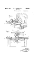
Fig. 1 is a perspective view of a preferred form of our invention, illustrating its use by the user while resting in bed, and similarly for invalid purposes; the movable tray portion is illustrated adjusted at an elevated and tilting position;
Fig. 2 is a central verticalsection of our device illustrated in Fig. 1, on enlarged scale;
Fig. 3 is a sectionalelevation on line 33 of Fig. 2;
Fig. 4 is a central vertical sectional view similar to Fig. 3, but showing the movable tray portion in depressed position; and
Fig. 5 is a top plan view of Fig. 4, on a somewhat reduced scale.
Referring to the drawings, the invention is particularly adapted for use by the user while in bed, as at leisure for breakfast or other service, or for invalid or like purposes.
It will be understood that the manner of use of the invention is not restricted as above indicated and that suitable modifications of the structure of our tray table as required are made for such other purposes.
legs of the tray are relatively short and uniform in height, to thereby position the top 11 of the tray within convenient reach of the user while seated in bed. As is illustrat ed in Fig. 1, our invention is applicable for the service of a meal, such as breakfastas indicated by the coffee pot, saucer, sugar bowl and cream pitcher, which may be conveniently placed upon the stationary portion 12 of the tray top. Such stationary tray portion 12 may extend peripherally completely about the top 11 and may be provided with the elevated guard strip 13, which may extend about three sides, excepting the side 14, which is particularly arranged, as by cutting away inwardly as indicated at 15, to be positioned approximate the user.
The movable tray portion 16 is adjustably mounted relative to. the stationary tray portion 12 and is supported for elevated'or' tiltmg position for receiving a book, newspaper, a dish or other use as may be desired.
A convenient form of such elevatable or tiltable support is had by the provision of a pair of lazy tongs 17, 17, the respective lower link ends of which are pivotally mounted at 18, 19, for the indicated lowermost long and short link lengths 17a, by suitable, headed plvot pins secured to the oppositely disposed, verticallyextending brackets 20, 20. The upper horizontally flanged portions 21 of the brackets 20, are secured by screws or the like (not shown) to the under face of the stationary tray portion 12.
To the upper link ends of each of the lazy tongs 17, 17, is pivoted an adjustable plate 22, namely, to the indicated long and short links 176, 17 6; each plate 22 is provided with an arcuate slot 23. The movable tray 16 is pivotally supported on the oppositely disposed plates 22 by means of the bracket 24 pivoted at 25 by the indicated headed pivot pins. The upper, horizontally flanged portion 26 of each plate 22 is secured by screws or the like (not shown) to the under face of the movable tray 16'.
Projecting through each arcuate slot 23, is a pin 27, which is secured at its fixed end to the bracket 24 and threaded at its free end to receive a winged nut 28 or the like, for
locking each bracket 24 to its plate 22. The movable tray portion 16 may be provided with a guard strip 29, and particularly at its side corresponding to the side 14 of the tray top. As indicated in Fig. 2, the movable tray portion 16 may be tilted from any horizontal position indicated in full outline to any inclined position indicated in dot and dash outline 16, the guard 29 in such 1nclined position serving to prevent a book or the like from sliding from the movable tray portion.
Preferably, the movably tray portlon 1s provided with the finger holds mdicated at 30, 30, see Fig. 5, such as comprising a dished metal plate countersunk relative to the upper surface of the movable tray portion 16 and provided with pivoted rings 31, of semi-circumferential length, the rings being arranged to be swung upwardly for grasping by the fingers when it is desired to raise or lower the movable tray portion 16, and to present a smooth surface with the tray portion 12 when in loweredv position.
It will be observed that when the tray portion 16 has been elevated, access to the winged nuts 28 is freely had at the opposite sides of the movable tray portion. When it is desired to depress the movable tray portion 16 to its lowermost position, the winged nuts 28 are loosened to permit relative movement of the link members of the lazy tong 17, the number and lengths of the lazy tong members 17 being selected to position the movable tray 16 substantially flush with the outer, stationary tray portion 12 when the members of the lazy tongs 17 are moved to fully contracted position, as indicated in Fig. 4.
If desired, and as is illustrated in the drawings, the guard edge strips 32 are provided at the inner margin of the stationary tray portion 12.
Whereas, we have described our invention by reference to specific forms thereof, it will be understood that many changes and modifications may from the spirit of the invention.
We claim 1. A table comprising a movable top portion, a stationary top portion substantially completely surrounding said movable top portion, a pair of lazy tong members disposed oppositely of said movable to portion, means for pivoting the lower lin elements of said lazy tong members to said stationary top portion, plates pivotally carried by the upper link elements of said lazy tong members, said plates respectively having arcuate grooves, depending members secured to the under face of said movable top portion, and means respectively passing through said arcuate grooves for securin said depending members to said plates, to thereby adjust the angular position of said movable top portion relative to said stationary top portion.
be made without departing 4 2. In a bed table, a stationary top portion a movable top portion disposed inwardly of said stationary top portion, a pair of lazy tong members, means for ,ivotally supporting the lower link elements of said lazy tong members to stationary top portion to allow said movable top portion to fold down into the same plane with said stationary top portion, plates carried by the upper link elements of said lazy tong members, said plates having arcuate faces, and means for adjustably supporting said movable top portion to said plates, said supporting meanscomprising locking elements co-acting with said arcuate faces.
3. In a bed table, a stationary top portion, a movable top portion disposed inwardly of said stationary top portion, a pair of lazy tong members, means for pivotally supporting the lower link elements of said lazy tong members to said stationary top portion, and means carried by the up er link elements of said lazy tong members or effecting angular movement of said movable top portion relative to said lazy tong supportlng members.
In testimony whereof we have signed this specification this 10th day of August, 1928.
WILLARD C. WETMORE. RICA HARWOOD SEELEY.
Priority Applications (1)
| Application Number | Priority Date | Filing Date | Title |
|---|---|---|---|
| US331935A US1853526A (en) | 1929-01-11 | 1929-01-11 | Tray table |
Applications Claiming Priority (1)
| Application Number | Priority Date | Filing Date | Title |
|---|---|---|---|
| US331935A US1853526A (en) | 1929-01-11 | 1929-01-11 | Tray table |
Publications (1)
| Publication Number | Publication Date |
|---|---|
| US1853526A true US1853526A (en) | 1932-04-12 |
Family
ID=23295986
Family Applications (1)
| Application Number | Title | Priority Date | Filing Date |
|---|---|---|---|
| US331935A Expired - Lifetime US1853526A (en) | 1929-01-11 | 1929-01-11 | Tray table |
Country Status (1)
| Country | Link |
|---|---|
| US (1) | US1853526A (en) |
Cited By (4)
| Publication number | Priority date | Publication date | Assignee | Title |
|---|---|---|---|---|
| US2587469A (en) * | 1947-11-12 | 1952-02-26 | Wayland F Herring | Typewriter support |
| US4431239A (en) * | 1980-10-01 | 1984-02-14 | Matti Vainikka | Pivot means |
| US6056129A (en) * | 1995-04-14 | 2000-05-02 | Ahearn; David J. | Dental delivery platform |
| NL1038533C2 (en) * | 2011-01-22 | 2012-07-24 | Teachyou B V | Support system for display device. |
-
1929
- 1929-01-11 US US331935A patent/US1853526A/en not_active Expired - Lifetime
Cited By (4)
| Publication number | Priority date | Publication date | Assignee | Title |
|---|---|---|---|---|
| US2587469A (en) * | 1947-11-12 | 1952-02-26 | Wayland F Herring | Typewriter support |
| US4431239A (en) * | 1980-10-01 | 1984-02-14 | Matti Vainikka | Pivot means |
| US6056129A (en) * | 1995-04-14 | 2000-05-02 | Ahearn; David J. | Dental delivery platform |
| NL1038533C2 (en) * | 2011-01-22 | 2012-07-24 | Teachyou B V | Support system for display device. |
Similar Documents
| Publication | Publication Date | Title |
|---|---|---|
| US3194403A (en) | Holder on upright support of detachable rotatable trays | |
| US2723037A (en) | Adjustable tray having glass retaining means | |
| US2771124A (en) | Divan with independently adjustable back and seat | |
| US3315858A (en) | Service tray | |
| US2208945A (en) | Combined reclining chair and reading stand | |
| US3146738A (en) | Tray adapted to be secured to a chair for an invalid | |
| US1676108A (en) | Convertible table | |
| US1821060A (en) | Adjustable bookrest | |
| US1853526A (en) | Tray table | |
| US3622199A (en) | Adjustable desk and chair combination | |
| US1133804A (en) | Make-up table. | |
| US1892745A (en) | Reading stand | |
| US1765514A (en) | Bed table | |
| US1928327A (en) | Hospital serving cabinet | |
| US804019A (en) | Commode. | |
| US2175488A (en) | Footrest | |
| US2723891A (en) | Adjustable bracket for sliding table top | |
| US1645769A (en) | Combination desk and table | |
| US2044675A (en) | Adjustable seat | |
| US2192574A (en) | Book rest and copy holder | |
| US4177739A (en) | Vertically adjustable table | |
| US1976034A (en) | Table with adjustable rack | |
| US2277929A (en) | Perpetual inventory device | |
| US1339525A (en) | Serving apparatus for dining-tables | |
| US3815967A (en) | File device |