US1853510A - Indicator - Google Patents
Indicator Download PDFInfo
- Publication number
- US1853510A US1853510A US334496A US33449629A US1853510A US 1853510 A US1853510 A US 1853510A US 334496 A US334496 A US 334496A US 33449629 A US33449629 A US 33449629A US 1853510 A US1853510 A US 1853510A
- Authority
- US
- United States
- Prior art keywords
- drum
- indicator
- carriage
- dial
- disk
- Prior art date
- Legal status (The legal status is an assumption and is not a legal conclusion. Google has not performed a legal analysis and makes no representation as to the accuracy of the status listed.)
- Expired - Lifetime
Links
Images
Classifications
-
- G—PHYSICS
- G01—MEASURING; TESTING
- G01C—MEASURING DISTANCES, LEVELS OR BEARINGS; SURVEYING; NAVIGATION; GYROSCOPIC INSTRUMENTS; PHOTOGRAMMETRY OR VIDEOGRAMMETRY
- G01C9/00—Measuring inclination, e.g. by clinometers, by levels
- G01C9/02—Details
- G01C9/08—Means for compensating acceleration forces due to movement of instrument
Definitions
- This invention is a device for indicatingthe inclination or angle assumed by an aeroplane when banking, climblng or descending.-
- the invention seeks to provide asimple, -ineX-' pensive and automatic device which may be secured in an aeroplane in front of the pilot so that it may be easily read by him and which will operate instantly to indicate departures from an even keel.
- the invention is illustrated in the accompanying drawings and will be hereinafter fully set fort-h.
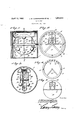
- Figure 1 is a longitudinal section through a casing containing the operating mechanism of an indicator embodying the invention
- the casing 1 is secured in the areoplane by any convenient means and is so located that one end 2 will be in theview range of the pilot, said end being referred to as the front end, for convenience, and being equipped with a pane 3 of transparent material covering the open end and permitting a reading of the indexes.
- the fixed dial is secured in the case 1, said dial consisting of an annulus 4 having radial arms 5 extending from low points thereof to its center to constitute a support for the a front bearing of the carriage.
- the annulus In its upper portion, the annulus tcarries graduations, indicated at 6, which may be of any'approved form and which cooperate with a movable indicator to denote the degree of inclination assumed in banking.
- the carriage? is a rectangular frame provided at its front end with i I a bearing point 8 adapted to engage'in the,
- the indicator 10 is secured-rigidly to the front end of the carriage and ispreferably in the V v so I form of a disk fitting closely to the annulus 1 1 or stationarydial and having its normally horizontal diameter definedby a line 11 contrasting with the face of the disk, so as to be easily read, and indicating the true horizon.
- Cooperating index markers 12 are provided on the fixed dial to aline with the line 11 and thereby aid the pilot in reading the indi- 13 marked upon its face at its normally highest point tocoop'erate with the graduations 6 upon the stationary dial andthereby give the pilot a correct readingof the degree of bank.
- a drumle is rotatably mounted within, the
- the carriage 7 has its circumferential surface calibrated in degrees in both directions from the zero point, as indicated at 15.
- the rotary indicator disk has'a bezel 16 stamped cator.
- the rotating disk- also has a pointer I p in its upper portion to fit closely to the cir- 'cumference ofthe drum and facilitate a read ing of the'same.
- the index marker 13 is con tinued acrossthe top wall of the bezel, and at the center of each side wall is a tapered lug 17 which will facilitate the reading of the drum.
- the drum consists of a disk 18 having a circumferential flange or rim bearing the calibrations 15.
- the drum is carriedby a shaft 19, the ends ofwhich are journaled in the sides of the carriage 7, as shown in Fig. 3, the shaft being provided with a fixed collar 20 bearing against the outer side of the disk 7 18 and a movable collar 21 which is mounted upon the. shaftat theinner side of the disk.”
- the movable collar may be adjusted upon and j I secured to the shaft19 in any preferred mannerand between the same and the disk 18 is a bar 22 which is clamped against the disk 18 by said collar, 'as willjbe understood upon reference to Fig. 3.
- the parts will appear as shown in Fig. 2, the index 13 alining with the central graduation 6 and the horizon line 17 V alining with the markers 12 while the drum has its zero point alined with the indicator lugs 17.
- the drum will rotate about its pivotal support in the carriage 7 so that the zero point thereof will be moved away from the lugs 17 and a different calibration or degree mark of the drum will be brought into alinement with said 1 lugs.
- the angle at which the plane is rising or falling will thus be automatically and quickly denoted and may be read by the pilot.
- the carriage 7 will rotate upon its' bearings so that the index marker 13 will be shifted relative to the graduations 6 and the horizon line 11 will be shifted relative to the markers 12, the pilot being thereby notified if his bank is sufficient for a safeturn.
- the floats or hollow members 26 and 31 tend to remain at the top of the device in all positions so that there is a constant tendency of the working elementsto remain in a single vertical plane.
- the weights-27 and 30 cooperate with the floats to accomplish this end.
- the bar 22 with its enlarged ends 23 is rather heavy and acts with. the weights 27, and 30 intending to maintain theworking elements in a vertical plane.
- the case isconstructed with leak-proof joints and it maybe provided with a filling opening through which a stabilizing liquid such as alcohol, may be poured,'the opening being permanently closed by sealing when the .case has been filled.
- the presence of the stabilizing liquid will prevent the weights and floats imparting a erky motion to the several working parts and, consequently, stability in the device and accuracy in the readings will be maintained.
- the drum and frame oscillating in planes at a right angle to each other and the calibrated circumference of the drum being'viewable through the open end of the casing, a fixed dial in the open end of the casing receiving one pivot of the frame, and a rotatable indicator disk secured to the frame immediately at the rear of the dial and cooperating with the'dial and having a bezel extending close to the circumference of the drum to permit reading of the drum.
- An indicator of the type described com prising acase having an open end, a frame pivotally mounted at the ends of the case, a
- An indicator of the type described comprising a casing having an open end, a stationary dial comprising an annulus secured in the open end of the casing and having graduations upon its upper portion and radial armsextending from its lower portion, a carriage journaled in the upper ends of said radial arms and in the casing at a point remote from the open end of the casin a calibrated'drum pivotally mounted in the carriage, and a rotatableindicator disk secured upon the carriage to cooperate with the fixed dial and having asight opening through which the drum may be viewed, the disk hav-. ing a horizon line marker upon its normal- 11 'ly horizontal diameter and the stationary dial having markers to cooperate with said line upon its marginal portion.
Landscapes
- Physics & Mathematics (AREA)
- Engineering & Computer Science (AREA)
- General Physics & Mathematics (AREA)
- Radar, Positioning & Navigation (AREA)
- Remote Sensing (AREA)
- Indicating Or Recording The Presence, Absence, Or Direction Of Movement (AREA)
Description
April 12, 1932.
J. M. CUNNINGHAM ET AL INDICATOR Filed Jan. 23, 192 9 wwawbtou JMC aiming/tam. J. 115 'zmnzln ghalfiv,
/ attozmuga Patented Apr. 12, 1932 uNrrsn sr rEs. PA ENT oFFIc JOSEPH M. CUNNINGHAM AND Jomv w. CUNNINGHAM, or KANSAS crrm'mrssounr INDICATOR Application. filedlanuary 23, 1929. Serial No. 334,496. c
This invention is a device for indicatingthe inclination or angle assumed by an aeroplane when banking, climblng or descending.- The invention seeks to provide asimple, -ineX-' pensive and automatic device which may be secured in an aeroplane in front of the pilot so that it may be easily read by him and which will operate instantly to indicate departures from an even keel. The invention is illustrated in the accompanying drawings and will be hereinafter fully set fort-h.
In the drawings:
Figure 1 is a longitudinal section through a casing containing the operating mechanism of an indicator embodying the invention,
relatively coh'ol, which will absorb violent movements e of the operating devices and'thereby prevent jumping or uneven action in the indicating elements. The casing 1 is secured in the areoplane by any convenient means and is so located that one end 2 will be in theview range of the pilot, said end being referred to as the front end, for convenience, and being equipped with a pane 3 of transparent material covering the open end and permitting a reading of the indexes. Immediately at the rear of the pane?) and bearing against the same, the fixed dial is secured in the case 1, said dial consisting of an annulus 4 having radial arms 5 extending from low points thereof to its center to constitute a support for the a front bearing of the carriage. In its upper portion, the annulus tcarries graduations, indicated at 6, which may be of any'approved form and which cooperate with a movable indicator to denote the degree of inclination assumed in banking. The carriage? is a rectangular frame provided at its front end with i I a bearing point 8 adapted to engage'in the,
upper end of the support provided by the arms 5 of the relatively stationary dial, as shown most clearly in Fig. 1, while the rear end-of the carriage is supported upon anadjustable needle point bearingct) mounted in the end wall of the case, as shown in Fig. 1. The indicator 10 is secured-rigidly to the front end of the carriage and ispreferably in the V v so I form of a disk fitting closely to the annulus 1 1 or stationarydial and having its normally horizontal diameter definedby a line 11 contrasting with the face of the disk, so as to be easily read, and indicating the true horizon.
Cooperating index markers 12 are provided on the fixed dial to aline with the line 11 and thereby aid the pilot in reading the indi- 13 marked upon its face at its normally highest point tocoop'erate with the graduations 6 upon the stationary dial andthereby give the pilot a correct readingof the degree of bank.
A drumle is rotatably mounted within, the
The drum consists of a disk 18 having a circumferential flange or rim bearing the calibrations 15. The drum is carriedby a shaft 19, the ends ofwhich are journaled in the sides of the carriage 7, as shown in Fig. 3, the shaft being provided with a fixed collar 20 bearing against the outer side of the disk 7 18 and a movable collar 21 which is mounted upon the. shaftat theinner side of the disk."
The movable collar may be adjusted upon and j I secured to the shaft19 in any preferred mannerand between the same and the disk 18 is a bar 22 which is clamped against the disk 18 by said collar, 'as willjbe understood upon reference to Fig. 3. The en'dsof the oar-are IOU carriage, the arms 29 carrying weights 30 at their lower ends, while the arms 28 support at their upper ends" floats 31, and it will .be noted upon reference to Fig. 1 that the floats 31 are elongated so that one float is provided at each side of the drum and said float constitutes a connection between the adjacent arms 28.
Assuming that the plane is on an even keel,
the parts will appear as shown in Fig. 2, the index 13 alining with the central graduation 6 and the horizon line 17 V alining with the markers 12 while the drum has its zero point alined with the indicator lugs 17. Should the plane be steered into a rise or a'drop, the drum will rotate about its pivotal support in the carriage 7 so that the zero point thereof will be moved away from the lugs 17 and a different calibration or degree mark of the drum will be brought into alinement with said 1 lugs. The angle at which the plane is rising or falling will thus be automatically and quickly denoted and may be read by the pilot. Should the plane be entering a turn, the carriage 7 will rotate upon its' bearings so that the index marker 13 will be shifted relative to the graduations 6 and the horizon line 11 will be shifted relative to the markers 12, the pilot being thereby notified if his bank is sufficient for a safeturn.
The floats or hollow members 26 and 31 tend to remain at the top of the device in all positions so that there is a constant tendency of the working elementsto remain in a single vertical plane. The weights-27 and 30 cooperate with the floats to accomplish this end. The bar 22 with its enlarged ends 23 is rather heavy and acts with. the weights 27, and 30 intending to maintain theworking elements in a vertical plane. As previously stated, the case isconstructed with leak-proof joints and it maybe provided with a filling opening through which a stabilizing liquid such as alcohol, may be poured,'the opening being permanently closed by sealing when the .case has been filled. The presence of the stabilizing liquid will prevent the weights and floats imparting a erky motion to the several working parts and, consequently, stability in the device and accuracy in the readings will be maintained. i
Having thus described claim r 1'. An indicator of the type described comthe invention, we
' prising a casi ng having an open end, a frame pivotally mounted at the ends of the casing,
trally within the frame and having a calibrated circumference, the drum and frame oscillating in planes at a right angle to each other and the calibrated circumference of the drum being'viewable through the open end of the casing, a fixed dial in the open end of the casing receiving one pivot of the frame, and a rotatable indicator disk secured to the frame immediately at the rear of the dial and cooperating with the'dial and having a bezel extending close to the circumference of the drum to permit reading of the drum.
2. An indicator of the type described com prising acase having an open end, a frame pivotally mounted at the ends of the case, a
the dial and cooperating with the fixed dial and having a bezel extending close to the circumference of the drum to permit reading of the drum, the bezel being provided with indicator elements cooperating with the calibrations on the drum and there being an index, at the top of the bezel extending to and cooperating, with the graduations on the face of the rotary dial.
3. An indicator of the type described comprising a casing having an open end, a stationary dial comprising an annulus secured in the open end of the casing and having graduations upon its upper portion and radial armsextending from its lower portion, a carriage journaled in the upper ends of said radial arms and in the casing at a point remote from the open end of the casin a calibrated'drum pivotally mounted in the carriage, and a rotatableindicator disk secured upon the carriage to cooperate with the fixed dial and having asight opening through which the drum may be viewed, the disk hav-. ing a horizon line marker upon its normal- 11 'ly horizontal diameter and the stationary dial having markers to cooperate with said line upon its marginal portion.
In testimony whereof we afiix our signatures.
JOSEPH M. CUNNINGHAM. [11. s.] JOHN W. CUNNINGHAM; [1 s] a drum pivotally mounted atits sides cen-
Priority Applications (1)
| Application Number | Priority Date | Filing Date | Title |
|---|---|---|---|
| US334496A US1853510A (en) | 1929-01-23 | 1929-01-23 | Indicator |
Applications Claiming Priority (1)
| Application Number | Priority Date | Filing Date | Title |
|---|---|---|---|
| US334496A US1853510A (en) | 1929-01-23 | 1929-01-23 | Indicator |
Publications (1)
| Publication Number | Publication Date |
|---|---|
| US1853510A true US1853510A (en) | 1932-04-12 |
Family
ID=23307478
Family Applications (1)
| Application Number | Title | Priority Date | Filing Date |
|---|---|---|---|
| US334496A Expired - Lifetime US1853510A (en) | 1929-01-23 | 1929-01-23 | Indicator |
Country Status (1)
| Country | Link |
|---|---|
| US (1) | US1853510A (en) |
Cited By (1)
| Publication number | Priority date | Publication date | Assignee | Title |
|---|---|---|---|---|
| US2482504A (en) * | 1946-08-12 | 1949-09-20 | Thomas D Pennington | Inclinometer |
-
1929
- 1929-01-23 US US334496A patent/US1853510A/en not_active Expired - Lifetime
Cited By (1)
| Publication number | Priority date | Publication date | Assignee | Title |
|---|---|---|---|---|
| US2482504A (en) * | 1946-08-12 | 1949-09-20 | Thomas D Pennington | Inclinometer |
Similar Documents
| Publication | Publication Date | Title |
|---|---|---|
| US2924022A (en) | Rotary indicators | |
| US2859725A (en) | True vertical indicator | |
| US1853510A (en) | Indicator | |
| US2032245A (en) | Flow meter | |
| US2177244A (en) | Anemometer with altitude correction | |
| US1397490A (en) | Inclinometer | |
| US1360102A (en) | Grade-meter | |
| US2142124A (en) | Angle measuring device | |
| US2353911A (en) | Level indicator | |
| US2202154A (en) | Aperiodic compass | |
| US2015627A (en) | Aircraft and artillery observation instrument | |
| US2141173A (en) | Geological instrument | |
| US1667840A (en) | Instrument for indicating direction of forces | |
| US3978730A (en) | Indicating instruments | |
| US2430814A (en) | hagner | |
| US4012960A (en) | Pressure gauge with expansible bellows | |
| US2205574A (en) | Oscillative indicating instrument | |
| US2300710A (en) | Universal flight indicator | |
| GB2061503A (en) | Inclinometer | |
| US2073352A (en) | Adjustable direction-finder chart | |
| US1863044A (en) | Pendulum bank and climb indicator for aeroplanes | |
| US1282859A (en) | Scale. | |
| CN103175511A (en) | Lever using buoyancy | |
| US2312307A (en) | Hydrometer | |
| US2206420A (en) | Level and clinometer |