US1853498A - Sheet glass scoring device - Google Patents
Sheet glass scoring device Download PDFInfo
- Publication number
- US1853498A US1853498A US68829A US6882925A US1853498A US 1853498 A US1853498 A US 1853498A US 68829 A US68829 A US 68829A US 6882925 A US6882925 A US 6882925A US 1853498 A US1853498 A US 1853498A
- Authority
- US
- United States
- Prior art keywords
- sheet
- glass
- motor
- scoring
- scoring device
- Prior art date
- Legal status (The legal status is an assumption and is not a legal conclusion. Google has not performed a legal analysis and makes no representation as to the accuracy of the status listed.)
- Expired - Lifetime
Links
- 239000005357 flat glass Substances 0.000 title description 4
- 239000011521 glass Substances 0.000 description 9
- 238000000137 annealing Methods 0.000 description 2
- 230000001788 irregular Effects 0.000 description 2
- 239000002699 waste material Substances 0.000 description 2
- 229910000831 Steel Inorganic materials 0.000 description 1
- 229910003460 diamond Inorganic materials 0.000 description 1
- 239000010432 diamond Substances 0.000 description 1
- 238000006073 displacement reaction Methods 0.000 description 1
- 230000000694 effects Effects 0.000 description 1
- 239000006060 molten glass Substances 0.000 description 1
- 239000010959 steel Substances 0.000 description 1
Images
Classifications
-
- C—CHEMISTRY; METALLURGY
- C03—GLASS; MINERAL OR SLAG WOOL
- C03B—MANUFACTURE, SHAPING, OR SUPPLEMENTARY PROCESSES
- C03B33/00—Severing cooled glass
- C03B33/02—Cutting or splitting sheet glass or ribbons; Apparatus or machines therefor
- C03B33/023—Cutting or splitting sheet glass or ribbons; Apparatus or machines therefor the sheet or ribbon being in a horizontal position
- C03B33/027—Scoring tool holders; Driving mechanisms therefor
Definitions
- the present invention relates to a sheet glass scoring device.
- An object of the presentinvention is to provide a scoring device wherein a sheet of glass may be divided up into suitable lengths,
- Another object of the invention is to provide an apparatus wherein a carriage may be made to move with a ribbon of glass, the said carriage carrying thereon a power driven rotatable wheel which may be moved transversely of the ribbon of glass to score the same, after which the end of the ribbon may be separated from the main body.
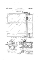
- Fig. 1 is a top plan vie-w of a form of the as apparatus
- Fig. 2 is an end view thereof
- Fig. 3 is a front elevation
- Fig. 4 is a top plan view of the motor, partially broken away to show the switching o mechanism.
- the numeral 5 designates a ribbon of glass which may be continuousl drawn from a mass of molten glass. As i lustrated in the drawings the ribbon of glass is arranged in the horizontal plane.
- the sheet In the Colburn type of machine illustrated in Patent No. 1,248,809, granted Dec. 4, 1917 the sheet is drawn vertically from a mass of glass, after which it is deflected over a suitable member, passed over a flattening table,
- the present invention has particular reference to the severing of the sheet intolengths at the end of the annealin leer.
- the numeral 6 designates the cutting table which ordinarily comprises. a plurality of wooden blocks 7 hin edly con? nected as at 8 in an endless belt ormation, the blocks having associated therewith roller means 9 which run upon a track 10.
- the scoring device comprises a truck 11 operable upon a track 12.
- a track or rail 12 is arran ed at both sides of the cutting table, the true s running thereon by means of the l I wheels 13.
- a pinion 14 is carried each truck, the pinion being received to run
- the rack bars ma easily be lined up so that the pinions 14 wi I prevent one end of the scoring device moving without the other end moving.
- a straight ed e 17 arranged transversely of the cutting ta le is supported at its opposite ends by the trucks 11 and has mounted thereon a motor 18 carrying a scoring wheel 19.
- the scoring wheel 19 is preferably acarborundum or similar type of disc having an edge 20 thereon adapted to form a score mark as at 21 in Fig. 1. Suitable connections are made from the motor 18 to a-source of electrical energy.
- the motor is controlled by means of a handle 22 which is also used to move the scoring member across the straight edge 17 to produce a transverse score mark 21.
- the operating handle 22 is pivotally associated with a switching mechanism 23.
- the switching mechanism 23 may include any well known type of switch connected in series with the motor 18 and to which switch the handle- Fig.1t
- the switch 22 is adapted to be connected.
- the switch is so positioned that when the operator pulls upon the handle 22 to draw the tool across the sheet, the switch will be closed to complete the circuit through the motor and thus effect 0 eration of the disc.
- the scoring mechanism As arranged in he score mark is just starting, and to finish the score the scoring mechanism is moved across the sheet toward the operating levers 24 and 25. After the score has been made the lever 22 may be moved in the opposite direction to stop the rotation of the scorin disc 19.
- a sprin clip 26 may be provided to prevent accifental' displacement of the scoring member, and to also sufiiciently retard movement of the scoring disc until the switching portion 23 has been moved into or out of engagement as the case may be.
- a link mechanism 27 is in operable relation with the lever 24: so that the straight edge 17 may be moved toward or away from the 'sheet 5 which is to be scored.
- the straight edge 17 is carried at its opposite ends by posts 28 having connection with the link mechanism 27 and movable up and down the standards 16 carried by the trucks 11 by reason of the bearings 29 arranged around the said standards.
- Measuring means 30 may be associated with the scoring mechanism to indicate the length of sheet to be cut. After the desired length has been ascertained the straight edge may be lowered by means of the lever 24. After this adjustment has been made the scoring disc 19 may be moved along the sheet to score the same.
- a breaker mechanism 31 is raised to contact with the sheet by means of the lever 25 to separate the end of the ribbon from the remainder thereof.
- the scoring mechanism is preferably raised out of contact with the sheet prior to the raising of the breaker arms 31.
- a table for supportinga moving sheet of glass to be cut, a cross-member extending transversely above the table and movable with the sheet, a motor mounted upon the cross-memher for movement longitudinally thereof, a cutting tool movable with and operable from said motor, a switch for the motor, and an operating handle connected to said switch for moving the motor and cutting tool alon the cross-member and for also opening and closing the switch.
- a table for supporting a moving sheet of glass to be cut, a track arranged beneath a portion of the table, a truck movable along the track, a cross-member carried by the truck and extending transversely above the sheet, means for moving the cross-member relative to the truck to engage the sheet whereby said member will be caused to move therewith, a motor mounted upon the cross-member for movement longitudinally thereof, a cutting tool movable with and operable from said motor, a switch for the motor, and an operating handle connected to said switch and by means of which the motor and cutting tool are moved along the cross-member and the said switch opened and closed.
Landscapes
- Chemical & Material Sciences (AREA)
- Engineering & Computer Science (AREA)
- Materials Engineering (AREA)
- Organic Chemistry (AREA)
- Re-Forming, After-Treatment, Cutting And Transporting Of Glass Products (AREA)
Description
I April 12, 1932. Q E BLWEN 1,853,498
SHEET GLASS SCORING DEVICE Filed Nov. 13, 1925 gChar/es E. B/iven Fiq4.
AT T EIENEY.
INVE NTU'Q- V Patented Apr. 12, 1932 UNITED STATES PATENT OFFICE OfiARLES E. IBLIVEN, OF CHARLESTON, WEST VIRGINIA, ASSIGNOR TO LIBBEY-OWENS.
FORD GLASS OOMPANY, OF TOLEDO, OHIO, A CORPORATION 01 OHIO sum Grass sconme DEVICE Application filed November 13, 19115. Serial No. 68,829.
The present invention relates to a sheet glass scoring device.
An object of the presentinvention is to provide a scoring device wherein a sheet of glass may be divided up into suitable lengths,
each cut being parallel to the preceding cut the score for the out being accomplishe preferably by means of a power driven rotatable wheel. m Another object of the invention is to provide an apparatus wherein a carriage may be made to move with a ribbon of glass, the said carriage carrying thereon a power driven rotatable wheel which may be moved transversely of the ribbon of glass to score the same, after which the end of the ribbon may be separated from the main body.
Other objects and advantages of the invention will become apparent during the no course of the following description.
In the drawings wherein like numerals are employed to designate like parts throughout the same,
Fig. 1 is a top plan vie-w of a form of the as apparatus,
Fig. 2 is an end view thereof,
Fig. 3 is a front elevation, and
Fig. 4 is a top plan view of the motor, partially broken away to show the switching o mechanism.
In the drawings the numeral 5 designates a ribbon of glass which may be continuousl drawn from a mass of molten glass. As i lustrated in the drawings the ribbon of glass is arranged in the horizontal plane. In the Colburn type of machine illustrated in Patent No. 1,248,809, granted Dec. 4, 1917 the sheet is drawn vertically from a mass of glass, after which it is deflected over a suitable member, passed over a flattening table,
and through an annealing leer. After the sheet passes through the annealing leer, it is run out upon a cutting table where the. ribbon is severed into suitable lengths. The sheets thus removed from the ribbon are then cut into the desired commercial sizes. The present invention has particular reference to the severing of the sheet intolengths at the end of the annealin leer.
Heret'ofore it. has een common practice to along a rack bar 15.
have an operator at the cutting end of the machine who makes the score mark across the sheet with a diamond or steel cutter and without any guide means. As the sheet is moving it is ahnost impossible to make a cut parallel to the preceding cut or at right angles to, the edges thereof. As the finished commercial sheets must be squared up a considerable loss is had due to these irregular and ununiform score lines. In the present invention means are provided which are movable with the sheet and which permit a score line to be made at right angles to the sides of the sheet and parallel to the precedingcut so that no waste is had when the sheet is cut up into commercial sizes.
In the drawings the numeral 6 designates the cutting table which ordinarily comprises. a plurality of wooden blocks 7 hin edly con? nected as at 8 in an endless belt ormation, the blocks having associated therewith roller means 9 which run upon a track 10.
The scoring device comprises a truck 11 operable upon a track 12. A track or rail 12 is arran ed at both sides of the cutting table, the true s running thereon by means of the l I wheels 13. In order to insure perfect aliggiw ment of the trucks, a pinion 14 is carried each truck, the pinion being received to run The rack bars ma easily be lined up so that the pinions 14 wi I prevent one end of the scoring device moving without the other end moving.
A straight ed e 17 arranged transversely of the cutting ta le is supported at its opposite ends by the trucks 11 and has mounted thereon a motor 18 carrying a scoring wheel 19. The scoring wheel 19 is preferably acarborundum or similar type of disc having an edge 20 thereon adapted to form a score mark as at 21 in Fig. 1. Suitable connections are made from the motor 18 to a-source of electrical energy. The motor is controlled by means of a handle 22 which is also used to move the scoring member across the straight edge 17 to produce a transverse score mark 21. The operating handle 22 is pivotally associated with a switching mechanism 23. The switching mechanism 23 may include any well known type of switch connected in series with the motor 18 and to which switch the handle- Fig.1t
22 is adapted to be connected. The switch is so positioned that when the operator pulls upon the handle 22 to draw the tool across the sheet, the switch will be closed to complete the circuit through the motor and thus effect 0 eration of the disc. As arranged in he score mark is just starting, and to finish the score the scoring mechanism is moved across the sheet toward the operating levers 24 and 25. After the score has been made the lever 22 may be moved in the opposite direction to stop the rotation of the scorin disc 19. A sprin clip 26 may be provided to prevent accifental' displacement of the scoring member, and to also sufiiciently retard movement of the scoring disc until the switching portion 23 has been moved into or out of engagement as the case may be.
A link mechanism 27 is in operable relation with the lever 24: so that the straight edge 17 may be moved toward or away from the 'sheet 5 which is to be scored. The straight edge 17 is carried at its opposite ends by posts 28 having connection with the link mechanism 27 and movable up and down the standards 16 carried by the trucks 11 by reason of the bearings 29 arranged around the said standards. When the straight edge 17 is in a lowered position its own weight will create suflicient frictional engagement with the sheet to cause movement of the scoring mechanism with the sheet. Measuring means 30 may be associated with the scoring mechanism to indicate the length of sheet to be cut. After the desired length has been ascertained the straight edge may be lowered by means of the lever 24. After this adjustment has been made the scoring disc 19 may be moved along the sheet to score the same. After the sheet has been scored a breaker mechanism 31 is raised to contact with the sheet by means of the lever 25 to separate the end of the ribbon from the remainder thereof. The scoring mechanism is preferably raised out of contact with the sheet prior to the raising of the breaker arms 31.
After the end of the ribbon has been removed, the operation may be continued to cut 011' another length. By reason of the fact that the straight edge 17 moved with the sheet and as the pinions 14 and rack bars 15 maintain a straight edge 17 in a parallel relation with the end 32, no waste will be had due to irregular cutting. J t is to be understood that the form of the invention herewith shown and described is to be taken as the preferred embodiment of the same, and that various changes in the shape, size and arrangement of parts may be resorted to without departing from the spirit of the invention or the scope of the subjoined claims.
. Claims: I
1. In combination with a movable table adapted to carry a sheet of glass to be cut,
of a carriage disposed at one side of the sheet, a cross-member carried by said carriage and extending across and above the sheet, means for moving said'member to engage said sheet causing the same to be moved therewith, a rotatable scorin tool carried by said member, power actuated means for driving said tool, switching mechanism for said driving means, and manually operable means connected with said switching mechanism for operating the same and for also moving said tool and driving means along said member transversely of said sheet with the tool in contact therewith.
2. In sheet glass cutting apparatus, a table for supportinga moving sheet of glass to be cut, a cross-member extending transversely above the table and movable with the sheet, a motor mounted upon the cross-memher for movement longitudinally thereof, a cutting tool movable with and operable from said motor, a switch for the motor, and an operating handle connected to said switch for moving the motor and cutting tool alon the cross-member and for also opening and closing the switch. I
3. In sheet glass cutting apparatus, a table for supporting a moving sheet of glass to be cut, a track arranged beneath a portion of the table, a truck movable along the track, a cross-member carried by the truck and extending transversely above the sheet, means for moving the cross-member relative to the truck to engage the sheet whereby said member will be caused to move therewith, a motor mounted upon the cross-member for movement longitudinally thereof, a cutting tool movable with and operable from said motor, a switch for the motor, and an operating handle connected to said switch and by means of which the motor and cutting tool are moved along the cross-member and the said switch opened and closed.
Signed at Charleston, in the county of Kanawha, and State ofWest Virginia, this 9th day of November, 1925.
CHARLES E. BLIVEN.
Priority Applications (1)
| Application Number | Priority Date | Filing Date | Title |
|---|---|---|---|
| US68829A US1853498A (en) | 1925-11-13 | 1925-11-13 | Sheet glass scoring device |
Applications Claiming Priority (1)
| Application Number | Priority Date | Filing Date | Title |
|---|---|---|---|
| US68829A US1853498A (en) | 1925-11-13 | 1925-11-13 | Sheet glass scoring device |
Publications (1)
| Publication Number | Publication Date |
|---|---|
| US1853498A true US1853498A (en) | 1932-04-12 |
Family
ID=22084963
Family Applications (1)
| Application Number | Title | Priority Date | Filing Date |
|---|---|---|---|
| US68829A Expired - Lifetime US1853498A (en) | 1925-11-13 | 1925-11-13 | Sheet glass scoring device |
Country Status (1)
| Country | Link |
|---|---|
| US (1) | US1853498A (en) |
Cited By (4)
| Publication number | Priority date | Publication date | Assignee | Title |
|---|---|---|---|---|
| US2957244A (en) * | 1958-03-20 | 1960-10-25 | Internat Typographical Union O | Precision ruling and scribing device for line-up tables |
| US3164046A (en) * | 1959-06-19 | 1965-01-05 | Saint Gobain | Method and apparatus for automatically cutting a strip of glass |
| US3165017A (en) * | 1962-07-16 | 1965-01-12 | Saint Gobain | Method and apparatus for automatically cutting a strip of glass |
| US5321892A (en) * | 1991-11-26 | 1994-06-21 | Mutoh Industries Ltd. | Automatic paper-cutting device in plotter |
-
1925
- 1925-11-13 US US68829A patent/US1853498A/en not_active Expired - Lifetime
Cited By (4)
| Publication number | Priority date | Publication date | Assignee | Title |
|---|---|---|---|---|
| US2957244A (en) * | 1958-03-20 | 1960-10-25 | Internat Typographical Union O | Precision ruling and scribing device for line-up tables |
| US3164046A (en) * | 1959-06-19 | 1965-01-05 | Saint Gobain | Method and apparatus for automatically cutting a strip of glass |
| US3165017A (en) * | 1962-07-16 | 1965-01-12 | Saint Gobain | Method and apparatus for automatically cutting a strip of glass |
| US5321892A (en) * | 1991-11-26 | 1994-06-21 | Mutoh Industries Ltd. | Automatic paper-cutting device in plotter |
Similar Documents
| Publication | Publication Date | Title |
|---|---|---|
| US1853498A (en) | Sheet glass scoring device | |
| US1996387A (en) | Sheet glass apparatus | |
| US1946356A (en) | Glass cutting apparatus | |
| US2259765A (en) | Sheet glass breaking apparatus | |
| US1988565A (en) | Glass cutting apparatus | |
| US1117736A (en) | Sheet-glass-cutting machine. | |
| US1895779A (en) | Method and apparatus for cross cutting wire glass | |
| US1834143A (en) | Glass cutting apparatus | |
| US2198264A (en) | Apparatus for welding | |
| US1798625A (en) | Apparatus for trimming glass sheets | |
| US1469379A (en) | Sheet-glass-drawing mechanism | |
| US1970932A (en) | Sheet glass cutting apparatus | |
| US1755365A (en) | Cutting apparatus for sheet glass | |
| US2058307A (en) | Method of and apparatus for cutting wired glass | |
| US1973723A (en) | Apparatus for severing sheet glass | |
| US2197560A (en) | Sheet glass cutting apparatus | |
| US1785496A (en) | Apparatus for cutting sheet glass | |
| US1853298A (en) | Glass cutting apparatus | |
| US1999593A (en) | Glass cutting apparatus | |
| US1857492A (en) | Method and apparatus for completing pressed blown ware or blown ware | |
| US1720546A (en) | Glass-cutting apparatus | |
| US2002346A (en) | Cut-off mechanism for sheet material | |
| US1869044A (en) | Glass cutting mechanism | |
| US2270462A (en) | Cutting machine | |
| US1310451A (en) | Combined glass-machine |