US1853497A - Furnace pressure regulator - Google Patents
Furnace pressure regulator Download PDFInfo
- Publication number
- US1853497A US1853497A US532097A US53209731A US1853497A US 1853497 A US1853497 A US 1853497A US 532097 A US532097 A US 532097A US 53209731 A US53209731 A US 53209731A US 1853497 A US1853497 A US 1853497A
- Authority
- US
- United States
- Prior art keywords
- furnace
- suction
- air
- tube
- tubes
- Prior art date
- Legal status (The legal status is an assumption and is not a legal conclusion. Google has not performed a legal analysis and makes no representation as to the accuracy of the status listed.)
- Expired - Lifetime
Links
- 239000007789 gas Substances 0.000 description 22
- 238000000034 method Methods 0.000 description 2
- CVSVTCORWBXHQV-UHFFFAOYSA-N creatine Chemical compound NC(=[NH2+])N(C)CC([O-])=O CVSVTCORWBXHQV-UHFFFAOYSA-N 0.000 description 1
- 230000008595 infiltration Effects 0.000 description 1
- 238000001764 infiltration Methods 0.000 description 1
- 238000012986 modification Methods 0.000 description 1
- 230000004048 modification Effects 0.000 description 1
- 230000005855 radiation Effects 0.000 description 1
- 239000011435 rock Substances 0.000 description 1
Images

Classifications
-
- F—MECHANICAL ENGINEERING; LIGHTING; HEATING; WEAPONS; BLASTING
- F27—FURNACES; KILNS; OVENS; RETORTS
- F27D—DETAILS OR ACCESSORIES OF FURNACES, KILNS, OVENS OR RETORTS, IN SO FAR AS THEY ARE OF KINDS OCCURRING IN MORE THAN ONE KIND OF FURNACE
- F27D7/00—Forming, maintaining or circulating atmospheres in heating chambers
- F27D7/02—Supplying steam, vapour, gases or liquids
Definitions
- the present invention provides a relatively simple mechanical control apparatus for this purpose.
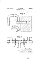
- Figure 2 is an enlarged fragmentary view of the furnace end of the apparatus.
- Figure 3 isan enlarged sectional elevation throughthe remote ends of the suction tubes.
- a pipe 3 is mounted in the opening or port 2 and is provided with a port or orifice 3 in its side wall which communicates with 4 the furnace end of a suction tube 4 which is provided with a restriction wall or choke 5 adjacent its other end remote from the furnace, having an orifice 5 therein of the same diameter as the orifice 3.
- the orifices 3 and 5 are only a fraction of the diameter of the pipe 4.
- a second suction tube 40 has one end located adjacent the furnace end of the tube 4 but turned on so as not to receive any of the hot gases issuing from the furnace through the pipe 3.
- the tube 40 is provided with a restricted port or orifice 40 at its furnace end 45 and with a restriction wall or choke 41 adj acent its end remote from the furnace, having an orifice 41 therein.
- the orifices 40 and 41 are of the same diameter and are equal to the orifices 3 and 5 in the tube 4.
- the tubes 4 and 40 have their ends remote from the furnace connected by a T-fittlng 42 with a suction conduit 7 which leads to a station 18.
- the station 18 includes a steam jet exhauster 17 controlled by a valve 20. It
- valve 20 is automatically controlled by rods 21 and 21 connected to anoil sealed bell 19.
- the bell 19 is located in a vessel 22 which is connected by a T-fitting 25 to the conduit 7.
- the rod 21 carries a counterweight 23. If the suction created by the exhauster 17, acting on the bell 19, overcomes the combined weights of the bell and counterweight 23, the bell rises and the rods 21 and 21 operate the valve 20 to throttle the suction, thereby maintaining a constant suction in'the pipe 7 and on the cold ends of the tubes 4 and 40.
- suction from the conduit or pipe 7 will draw gases or air from the tube 4 through the orifice 5 This suction will cause a flow of gases or air through the inlet orifice 3 into the tube 4.
- the suction in the tube 4 will increase until the same weight of gas or air enters into the conduit 4 through the orifice 3 as is withdrawn through the orifice5.
- the suction in the tube 4 remains con- I stant as long as the suction in the conduit or pipe 7 remains constant and the temperature of the gases or air flowing through the orifices of the tube 4 remains constant.
- the temperature at the outlet orifice 5 is atmosoheric, and therefore ma be considered consta'ntfor practical purposes.
- the temperature at the inlet orifice 3* varies con-.
- Furnace gases and air have substantially the same density at atmospheric temperature but the gases, say at 2000 degrees Fahrenheit,
- the second suction tube 40 receives atmospheric air at its furnace end and, therefore, the suction in this tube remains substantially constant at all times.
- the furnace or inlet r end of the tube 40 is located adjacent the furnace or inlet end of the tube 4 so'that the atmospheric air entering the tube will be of substantially the same temperature as the temperature of the cold air entering the fur- "nace through the pipe 3, The radiation of heat from the furnace will have some effect on the temperature of the air adjacent the furnace. Therefore, 1n order to properly 7 balance the suction of the tubes 4 and 40', it is desirable to draw. atmospheric air of the same temperature through the tubes.
- the suction in the tubes 4 and 40' is communicated to the balanced bells 47 and 48,
- I claim: 7 In a furnace pressure control the combination with a furnace having a port through which hot gases may escape when the furnace is above atmospheric pressure and through which atmospheric air will flow into the furnace when the furnace is operating below atmospheric pressure, of a pair of suction tubes, one of said tubes having one end in communication with said port in said furnace and the other of said tubes having one end in close proximity to said port and positioned so as not to receive the gases or air flowing through said port, said suction tubes having their other ends remote from said furnace, a control apparatus consisting ofa balanced beam, a sealed bell on each end of said beam, one of said tubes being connected adjacent its end remote from said fur- :nacetoone ofsaidbells and the other of said tubes being connected adjacent its end remote from said furnaceto the other of said bells, a restricted orifice adjacent each end of each of said tubes, means for providinga suction to the ends of each of said tubes remote from said furnace whereby the gas or air flowing through said furnace port will be drawn through the tube communicating with said port and atmospheric air will be drawn through the other
Landscapes
- Engineering & Computer Science (AREA)
- Mechanical Engineering (AREA)
- General Engineering & Computer Science (AREA)
- Tunnel Furnaces (AREA)
Description
April 12, 1932. F BLEYER' 1,853,497
FURNACE PRESSURE REGULATOR Filed April 22, 1951 2 Sheets-Sheet 1 leg].
[wen afar:
CH4E4E5 f ELL-FEE) April 1932- c. F. BLEYER I FURNACE PRESSURE REGULATOR Filed April 22, 1931 2 Sheets-Sheet 627448455 f. 525 542, M x M Patented Apr. 12, 1932 ATENT OFFICE CHARLES F. IBLEYER, OF LORAIN, OHIO FURNACE PRESSURE REGULATOR Application filed 41111122, 1931. Serial No. 532,097.
This invention relates to furnace pressure regulators and, while not limited thereto, relates more particularly to means for and a method of maintaining a balanced pressure in open hearth furnaces and the like.
In the operation of a furnace it is desirable to maintain a balance between the furnace pressure and the atmosphere if possible in order to retain the hot gases in the furnace and toprevent the infiltration of cold air.
The present invention provides a relatively simple mechanical control apparatus for this purpose.
In the drawings: I Figure 1 is an elevation of apparatus constructed in accordance with this invention.
Figure 2 is an enlarged fragmentary view of the furnace end of the apparatus.
Figure 3 isan enlarged sectional elevation throughthe remote ends of the suction tubes.
Referring more particularly to the drawings the numeral 2 designates an open hearth furnace which is provided with an opening 2 in its wall through which hot gases may escape from the furnace and air may enter the furnace in accordance to unbalanced pressure between the interior of the furnace and the atmosphere.
A pipe 3 is mounted in the opening or port 2 and is provided with a port or orifice 3 in its side wall which communicates with 4 the furnace end of a suction tube 4 which is provided with a restriction wall or choke 5 adjacent its other end remote from the furnace, having an orifice 5 therein of the same diameter as the orifice 3.
The orifices 3 and 5 are only a fraction of the diameter of the pipe 4.
A second suction tube 40 has one end located adjacent the furnace end of the tube 4 but turned on so as not to receive any of the hot gases issuing from the furnace through the pipe 3. The tube 40 is provided with a restricted port or orifice 40 at its furnace end 45 and with a restriction wall or choke 41 adj acent its end remote from the furnace, having an orifice 41 therein. The orifices 40 and 41 are of the same diameter and are equal to the orifices 3 and 5 in the tube 4.
The tubes 4 and 40 have their ends remote from the furnace connected by a T-fittlng 42 with a suction conduit 7 which leads to a station 18. The station 18 includes a steam jet exhauster 17 controlled by a valve 20. It
will be understood that any standard form of exhauster may be substituted for the ex hauster 17 if desired. The valve 20 is automatically controlled by rods 21 and 21 connected to anoil sealed bell 19.
The bell 19 is located in a vessel 22 which is connected by a T-fitting 25 to the conduit 7. The rod 21 carries a counterweight 23. If the suction created by the exhauster 17, acting on the bell 19, overcomes the combined weights of the bell and counterweight 23, the bell rises and the rods 21 and 21 operate the valve 20 to throttle the suction, thereby maintaining a constant suction in'the pipe 7 and on the cold ends of the tubes 4 and 40.
The tubes 4 and 40 are provided with branches and 46, respectively, closely adjacent their ends remote from the furnace which are in communication, respectively, with bells 47 and 48 mounted on the opposite ends of a balanced beam 49 and having their lower or open ends sealed in oil in a housing 11. The balanced beam 49 is connected by levers 80 and 31 to a valve 32 of a compressed air motor'13 which has its piston rod 14 connected by a cable or rope 15 to the damper 16 in the draft flue 16 of the furnace 2.
In operation, suction from the conduit or pipe 7 will draw gases or air from the tube 4 through the orifice 5 This suction will cause a flow of gases or air through the inlet orifice 3 into the tube 4. The suction in the tube 4 will increase until the same weight of gas or air enters into the conduit 4 through the orifice 3 as is withdrawn through the orifice5. After this equilibrium is "established, the suction in the tube 4 remains con- I stant as long as the suction in the conduit or pipe 7 remains constant and the temperature of the gases or air flowing through the orifices of the tube 4 remains constant. The temperature at the outlet orifice 5 is atmosoheric, and therefore ma be considered consta'ntfor practical purposes. The temperature at the inlet orifice 3*, however, varies con-.
siderably as at times the hot gas from the furnace flows through the inlet orifice and at other times cold air, which is bein drawn into the furnace, flows through tie inlet orifice.
Furnace gases and air have substantially the same density at atmospheric temperature but the gases, say at 2000 degrees Fahrenheit,
have only 21 per cent. of the density of atmospheric air. As a result,m:uch less weight of gases enters the inlet orifice when hot furnace gases are entering the tube 4 and, therefore, the suction in the tube 4 rises immediately and drops again when cold air enters. From the above it will be readily understood tliat'the suction in the tube 4 Varies in accordance with the temperature of the gaseous products drawn into said tube.
The second suction tube 40 receives atmospheric air at its furnace end and, therefore, the suction in this tube remains substantially constant at all times.
The furnace or inlet r end of the tube 40 is located adjacent the furnace or inlet end of the tube 4 so'that the atmospheric air entering the tube will be of substantially the same temperature as the temperature of the cold air entering the fur- "nace through the pipe 3, The radiation of heat from the furnace will have some effect on the temperature of the air adjacent the furnace. Therefore, 1n order to properly 7 balance the suction of the tubes 4 and 40', it is desirable to draw. atmospheric air of the same temperature through the tubes. The suction in the tubes 4 and 40' is communicated to the balanced bells 47 and 48,
, itedthereto since various modifications may be made without departing from the scope of our invention, as defined in the appended claims.
I claim: 7 1. In a furnace pressure control the combination with a furnace having a port through which hot gases may escape when the furnace is above atmospheric pressure and through which atmospheric air will flow into the furnace when the furnace is operating below atmospheric pressure, of a pair of suction tubes, one of said tubes having one end in communication with said port in said furnace and the other of said tubes having one end in close proximity to said port and positioned so as not to receive the gases or air flowing through said port, said suction tubes having their other ends remote from said furnace, a control apparatus consisting ofa balanced beam, a sealed bell on each end of said beam, one of said tubes being connected adjacent its end remote from said fur- :nacetoone ofsaidbells and the other of said tubes being connected adjacent its end remote from said furnaceto the other of said bells, a restricted orifice adjacent each end of each of said tubes, means for providinga suction to the ends of each of said tubes remote from said furnace whereby the gas or air flowing through said furnace port will be drawn through the tube communicating with said port and atmospheric air will be drawn through the other of said tubes and'the suction in the tube having the gas or air from said furnace port passing therethrough varying in accordance with the temperature and density ofsaid gas and air so as to unbalance the suction in said bells and rock said beam, and means operable by said beam for controlling the furnacedraft.
2. The combination with a furnace having a port therein through which hot gases-will issue when the pressure in the furnace is above atmospheric pressure, and through which atmospheric air will stream when the furnace is below atmospheric pressure, means for utilizing the differences in density of the gas and air flowing through said port to pro vide a suction varying in accordance with said density, means forrutilizing atmospheric air of substantially constant temperature and density to provide a suction of relatively constant value, and means for balancing the suction provided by said first named means against the suction provided by said second named means, and means operable by said balancing means for controlling the draft to said furnace.
3. .The method of automatically maintainin g balanced pressure in a furnacewhich consists in allowing hot gases fromthe furnace to issue from a port when the pressure in the furnace is above atmospheric pressure, and allowing cold air to stream into the furnace through the same port when the furnace is below atmospheric pressure, drawing the air or gases flowing through said opening with constant suction successively through a series of two orifices at opposite endsof a confined flow path thereby creatin differences in suction responsive to the di erences in temperature and density of said gas or air, drawing atmospheric air successively through a series of two orifices at opposite ends of a second confined flow path so as to provide a substantially constant suction between said orifices, said air being drawn through said orifices under the same head of suction as said air or gas from said furnace port, balancing the suction in said first named confined flow path against the suction in said second named confined fiow path and utilizing the differences between said suctions to, control the draft in said furnace.
In testimony whereof, I have hereunto set my hand.
CHARLES F. BLEYER.
Priority Applications (1)
| Application Number | Priority Date | Filing Date | Title |
|---|---|---|---|
| US532097A US1853497A (en) | 1931-04-22 | 1931-04-22 | Furnace pressure regulator |
Applications Claiming Priority (1)
| Application Number | Priority Date | Filing Date | Title |
|---|---|---|---|
| US532097A US1853497A (en) | 1931-04-22 | 1931-04-22 | Furnace pressure regulator |
Publications (1)
| Publication Number | Publication Date |
|---|---|
| US1853497A true US1853497A (en) | 1932-04-12 |
Family
ID=24120366
Family Applications (1)
| Application Number | Title | Priority Date | Filing Date |
|---|---|---|---|
| US532097A Expired - Lifetime US1853497A (en) | 1931-04-22 | 1931-04-22 | Furnace pressure regulator |
Country Status (1)
| Country | Link |
|---|---|
| US (1) | US1853497A (en) |
Cited By (1)
| Publication number | Priority date | Publication date | Assignee | Title |
|---|---|---|---|---|
| US2696325A (en) * | 1949-10-01 | 1954-12-07 | John E Beier | Paper bag dispenser |
-
1931
- 1931-04-22 US US532097A patent/US1853497A/en not_active Expired - Lifetime
Cited By (1)
| Publication number | Priority date | Publication date | Assignee | Title |
|---|---|---|---|---|
| US2696325A (en) * | 1949-10-01 | 1954-12-07 | John E Beier | Paper bag dispenser |
Similar Documents
| Publication | Publication Date | Title |
|---|---|---|
| US2378632A (en) | Apparatus for separating solids from liquids | |
| US1884896A (en) | Fluid analysis | |
| US1853497A (en) | Furnace pressure regulator | |
| US1745059A (en) | Pilot-controlled demand meter | |
| US2526898A (en) | Vapor temperature control | |
| US1721800A (en) | Apparatus for regulating combustion | |
| US1725374A (en) | Pilot-controlled demand meter | |
| US1573079A (en) | Apparatus for proportionately mixing air and gas | |
| US2246934A (en) | Fractional distillation | |
| US2244821A (en) | Combustion apparatus | |
| US1308569A (en) | Thomas b | |
| US2800919A (en) | Fluid flow regulator | |
| US1869442A (en) | Furnace pressure regulator | |
| US2906258A (en) | Steam generating apparatus | |
| US1591324A (en) | Gas and air mixing apparatus | |
| US2009711A (en) | Gravity flow control | |
| US2875736A (en) | Gas recirculation method and automatic apparatus for superheat control | |
| US2540778A (en) | Furnace control system | |
| US2586503A (en) | Fluid heater temperature control system | |
| US3066533A (en) | Temperature equalizing multiport water level gauge | |
| US1215669A (en) | Apparatus for controlling the velocity of a fluid flowing through a passage. | |
| US1338928A (en) | Regulation and apparatus therefor | |
| US966064A (en) | Hot-air furnace. | |
| US1383258A (en) | Constant-volume regulator for turbo-compressors | |
| US1751893A (en) | Regulation of combustion of gases in furnaces |