US1853492A - Strut construction - Google Patents
Strut construction Download PDFInfo
- Publication number
- US1853492A US1853492A US459748A US45974830A US1853492A US 1853492 A US1853492 A US 1853492A US 459748 A US459748 A US 459748A US 45974830 A US45974830 A US 45974830A US 1853492 A US1853492 A US 1853492A
- Authority
- US
- United States
- Prior art keywords
- wing
- strut
- struts
- fuselage
- lifting
- Prior art date
- Legal status (The legal status is an assumption and is not a legal conclusion. Google has not performed a legal analysis and makes no representation as to the accuracy of the status listed.)
- Expired - Lifetime
Links
Images
Classifications
-
- B—PERFORMING OPERATIONS; TRANSPORTING
- B64—AIRCRAFT; AVIATION; COSMONAUTICS
- B64C—AEROPLANES; HELICOPTERS
- B64C3/00—Wings
- B64C3/18—Spars; Ribs; Stringers
- B64C3/185—Spars
Definitions
- rlhe invention relates to airplanes and more particularly has reference to a strut therefor.
- struts or compressionmembers employed for bracing between the Wing surfacesof an airplane or between a Wing surface and the fuselage have generally been given a circular cross section.
- a strutV of this type has had a fairing added thereto so as to pro-duce a stream lined i0 section.
- Other constructions have also been employed for eecting such a section.
- the major object of this invention is the provision of an airplane strut provided With a lifting surface.
- An equally important object of the invention is t-he designing of a construction allowing a plurality of struts provided with lifting surfaces to be attached to a Wing of an airplane for the purpose of supporting the same.
- Another object of the invention is the designing of an airplane strut having a lifting surface portion to which is secured anextension column member.
- Still another object of the invention is the provision of an airplane strut having a lifting surface portion of an airfoil section, a
- Yet another object of the invention' is the designing of an airplane strut having a lifting surface portion adapted to be connected 40 to the fuselage of a plane and an extension column member connected to a Wing of the plane, the lifting surfacerof the strut being so positioned with respect to the Wing of the plane with which it is associated as to substantially prevent interference betweenV air currents adjacent said Wing and the lifting surface.
- a further object of the invention is the provision of a plurality of struts provided With lifting surfaces, the struts being connected to 1930. Serial N'o. 459,748.
- Still a further object of the invention is the provision of a design allowing the use of a plurality of lift struts, the
- each strut being connected to the the struts adjacent the Wing being additionally supported by a cross frame Which also ties the 'struts together.
- Still another object of the invention is the provision Aof a truss framework whereby the Wing supporting end of a strut may be spaced from the Wing surface and interference of air currents preve nted.
- the invention comprehends the provision of a novel strut or a compression member for supporting the Wings of an airplane, and also includes the positioning of a plurality of struts in tandem, one ybehind the other.
- One method of practically effecting the concept of the invention ⁇ istheprovision of a strut having an elongated lifting surface portion adapted to beconnected to the fuselage of the plane. To the lifting surface portion is secured an extension column member which is also connected to the Wing .With Which the strut isassociated.
- the struts on the same side of the fuselage are positioned parallel tofeach other and have their upper ends connected tothe Wing surface along thesarne chord of the Wing and their lo fuselage.
- a novel cross frame construction which is connected to the extension column members and the Wing is employed.
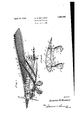
- sion column taken along the line 2-2 of Figure. ⁇ 1 andV shows in detail the connection of the struts to thel wing.
- Figure 1 Shown in Figure 1 is an airplane having a fuselage 17 ofthe cabin type.
- a wing -9 provided with ailerons 10.
- Wing 9 may be of any desired airfoil section and is formed ofthe usual spars 11, ribs l2, and surfacing material 13.
- the wing construction may be one of the all-metal type or'th'e ribs and spars'may be formed of'wood .and a suitable fabric covering material employed; f
- each strut is formed of aV spar .and rib construction
- each column member possesses a relatively small cross section, when compared withv that of the lifting surfaceV portion of the strut.
- extension column members are stream lined.
- the end of the lifting surface portion of each strut, adjacent has an outward taper 17.
- the end 15 of the lifting surface portion possesses a smaller cross section than. the main body of the'lifting surface. Because of the taper just mentioned, the cross sectional area of the liftingv surface portionv progressively increases from minimum at its end l5 to a maximum where the taper joins the main body ofthe lifting surface.
- the struts In positioning the struts so that they may function. as compression members for supporting' they wing'7 the end of. eacli extension member is secured to the wing ⁇ of the plane, while the free end of the lifting ⁇ surface portion is connected to the; fuselage..
- the struts are arranged in pairs on opposite sides of the fuselage, although more than two on each side of the wing may be. employed ifdesired.
- each extension column member 12 is secured to a suitablefitting 18 which isattachedl to one of the sp'ars of the wing.
- a short stubwinglt of any suitable airfoilf design, is mounted upon each side ofthe fuselage ⁇ adjacent the landing carriage, and to this the free end of the lifting surface. of the forward strut is secured.
- the. free end of thelifting surface ofthe rearward strut is attached directly' to the lower portion of the fuselage without the use' of' a stub wing.
- eachof thelift struts hasbeen shown positioned so as to have the same angle of incidence, it is understood that this vneed not necessarilybe followed.
- the angle of incidence of each lift strut may be of the same or differentsignand likewise of different degree.
- the angle of incidence of each liftV strut is less than that of themain wing. Itis tov be understood, however, that av greater angle of Vincidence may be given to the lift strut than tothe main wing without departing from the spirit of they invention or thescope ofthe appended claims.
- Whilestruts on the same sideiof the fuselage have been disclosed -as substantiallyT parallel to each other this arrangement may be varied so that ⁇ the rearward strut maybe connected to the fuselage at a point nearer the tail of the airplane than is shown.
- an exceedingly strong support having the effect of an A-frame for the wings would be provided.
- the load on the semi-span of a wing increases for increased angles of attack.
- the resultant of this load on the semi-wing span consequently changes its position with respect to the fuselage of the plane to which the semi-span is connected.
- the lateral center of pressure through which the resultant load passes moves outwardly towards the wing tips, and as the Vangle of attack decreases it moves inwardly towards the fuselage of the airplane.
- the lateral center of pressure thus has a range of travel and it is within this zone that the extension column members are connected to the wing.
- the length of the entire strut is determined by the location of the range of travel ofthe lateral center of pressure on the semi-wing span and the point at whichthe strut is connected to the fuselage.
- each strut is positioned at sucha point so as to take the resultant load directly and hence strengthen the wing at the greatest point of load thrust.
- extension column members may be connected to the wing at a point nearer the tips and without the range of center of pressure travel.
- a greater lifting surface would be provided for the struts.
- crossed tie wires 22 are employed. VThese wires are connected adjacent the wing surface to the vertical hanger 21 and to the lower end of the opposite hanger. In @dect they provide diagonal tension members of a truss construction and are placed under have their other ends secured of the lifting surface portion. However, in
- metal tubular construction is preferred, although it is to be understood that I-beams, T'-beams, built up box girders, or otherstructural beams and forms maybe employed if desired. In the latter instance,
- the extension column members may be coveredl with suitable fabric and stream lined or any other method of stream lining may be employed.
- the spars and ribs ofthe lifting surfaces of the struts are constructed of wood or metal as desired. Fabric surfacing material or metal may be used for ycovering the framef work formed by the spars and ribs. y
- extension column members which allow the airfoil section of thestrut tobestopped a considerable distance below the bottom surface of the wing, interference of air currents adjacent the lifting surface of the struts and the wing is substantially prevented. This interference is further pref vented by providing the tapered portion 17 near the end of the lifting surface of each strut. i f
- the struts are of benefit in that they may be so positioned.as.to 101W the. planeltolclirnb. at an'imicreased angle offarttalc' eonstructions'v also; affords strong and rigidly bracedcompression members which are ofic'omparatively light weight: Because ofthe-fact' that the extension columns arefso positioned'with'.respect to the lifting surface' cipal' sparsth'ereofwhich carry tliei greatest ofthe load' uponv the wing.V Thus will be appreciated that the load carried on the spar i'stransmitted directly tothe struts: and not. through the medium of inter'- mediaitefmembers.. Y Y lfVlclude' the invention liasfbeen shown as. ap-
- each of said struts being formed. with al lifting'sur-face portion having secured. thereto an extension. column member, the lifting'surface of one strut beingconnected directly to the fuselage ofthe plane, the other being connected to a' stub wing mountedron the fuselage of the plane, the extension column of eaclistrut being connected'to a spar of the Wing which the strut is associated and cross bracing. between the struts connected to. thefwing. y
- AnA air-foil strutV comprising a lifting surface portion and an extension column member secured thereto, said lifting surface portion having an. airfoil section formed of rib vand'spar' construction with surfacing material therefor, saiol ⁇ extension column member being stream lined, the lifting surface of they strut: adapted to be connected to a stub wing'monuted on the fuselage of an airplane and the extension column member adapted to besecured to awin'g of the airplane.
- each of'said struts provided withV a. lifting surface portion having an extension column member secured to the end thereof, the struts on each side of the fuselage being positioned in tandem one behind the other, the extension column members offeach strut being connected to the wing along the same chord and-,the lift surface portions of. the. forward strut being connected to a stub Wing mounted on the fuselage of the Y plane and the other being connected. directly to the: fuselage.
- GIUSEPPE M. BELLANCA.
Description
Patented Apr. 12, 1932 N ffl GIUSEPPE M. BELLANCA, F NEW CASTLE, DELAWARE STRUT CONSTRUCTION Application filed .Tune 7,
rlhe invention relates to airplanes and more particularly has reference to a strut therefor. ln the past struts or compressionmembers employed for bracing between the Wing surfacesof an airplane or between a Wing surface and the fuselage have generally been given a circular cross section. In some instances a strutV of this type has had a fairing added thereto so as to pro-duce a stream lined i0 section. Other constructions have also been employed for eecting such a section. HOW- ever, but little attention has been given to forming a strut of sufficient size and such shape as to provide a lifting surface, the art considering chiefly the advantage of eliminating parasitic resistance by stream lining the struts and making them of as small a cross section as is structurally feasible.
The major object of this invention is the provision of an airplane strut provided With a lifting surface. Y
An equally important object of the invention is t-he designing of a construction allowing a plurality of struts provided with lifting surfaces to be attached to a Wing of an airplane for the purpose of supporting the same.
Another object of the invention is the designing of an airplane strut having a lifting surface portion to which is secured anextension column member.
Still another object of the invention is the provision of an airplane strut having a lifting surface portion of an airfoil section, a
. stream lined extension column member being secured to the lifting portion of the strut.
Yet another object of the invention'is the designing of an airplane strut having a lifting surface portion adapted to be connected 40 to the fuselage of a plane and an extension column member connected to a Wing of the plane, the lifting surfacerof the strut being so positioned with respect to the Wing of the plane with which it is associated as to substantially prevent interference betweenV air currents adjacent said Wing and the lifting surface. A further object of the invention is the provision of a plurality of struts provided With lifting surfaces, the struts being connected to 1930. Serial N'o. 459,748.
the fuselage and a Wing of the plane and po` sitioned in tandem relation one behind the other.
Still a further object of the inventionis the provision of a design allowing the use of a plurality of lift struts, the
tioned in tandem struts being posifrom the leading to jthe trailing edge of the Wingon each side ofthe fuselage,
fuselage and the Wing,
each strut being connected to the the struts adjacent the Wing being additionally supported by a cross frame Which also ties the 'struts together.
Still another object of the inventionis the provision Aof a truss framework whereby the Wing supporting end of a strut may be spaced from the Wing surface and interference of air currents preve nted.
With these and'other objects in vievv,.which may be incident to my improvements, the invention consists in the parts and combina-r tions to be hereinafter set forth and claimed,l
with the understanding that the several necessary elements comprising my invention may be varied 1n construction, proportions and arrangement Without departing from the spirit and scope of the appended claims.
The invention comprehends the provision of a novel strut or a compression member for supporting the Wings of an airplane, and also includes the positioning of a plurality of struts in tandem, one ybehind the other. One method of practically effecting the concept of the invention `istheprovision of a strut having an elongated lifting surface portion adapted to beconnected to the fuselage of the plane. To the lifting surface portion is secured an extension column member which is also connected to the Wing .With Which the strut isassociated.
In use the struts on the same side of the fuselage are positioned parallel tofeach other and have their upper ends connected tothe Wing surface along thesarne chord of the Wing and their lo fuselage. For the purpose of strongly sup- Wer ends connected to the porting the struts and tying them together,l a novel cross frame construction which is connected to the extension column members and the Wing is employed.
In order to mak e my inventionmore clear- 'curedf an.
sion column taken along the line 2-2 of Figure. `1 andV shows in detail the connection of the struts to thel wing.
Throughout the drawings similar reference numerals refer to like parts in the differentv views. Shown in Figure 1 is an airplane having a fuselage 17 ofthe cabin type.
upon which is provided the customary tailY surfaces 2,` and rudder 3. The plane is driven by a suitable motor 4 to which is connectedfa propeller 5. Secured to the lower part ofthe fuselageis a landing' gear 6, of any convenient design, provided with wheels A t'aill skid 8 is also disclosed. Mounted upon the fuselage is a wing -9 provided with ailerons 10.
Wing 9 may be of any desired airfoil section and is formed ofthe usual spars 11, ribs l2, and surfacing material 13. The wing construction may be one of the all-metal type or'th'e ribs and spars'may be formed of'wood .and a suitable fabric covering material employed; f
' For the purpose ofsupporting the wing 9,' I have disclosed a novell form ofl strut which comprises'a liftingsurface portion 14 having an airfoilfsection (Figure 2) of any desired typeto they end 15 off which is seextensionv column member 16..
The liftingsurfaceportion Mof each strut is formed of aV spar .and rib construction,
VwhichV for the purpose of simplifyingrthe Upon the' sparv drawings hask been. omitted. and rib construction ju'st'mentioned, there is placed suitable surfacing or covering material 14.
There is secured to the lend 15 ofthe Ylifting` 'surface portion of each strut, as previously pointed out, an extension column member. 16. The extension `col-umu Amember. 16- is so positioned upon the lifting surface portion that the center of gravity ofits. cross section coincides with ythe center of gravity of the cross section of the lifting section portion, thus preventing theload transmitted 'to the lifting surface portion through the extenmember from being applied lec- C'en'trically., As may be obseiwed'V in Figure 1f, each column member possesses a relatively small cross section, when compared withv that of the lifting surfaceV portion of the strut.
.its extension column,
It is also to be observed that the extension column members are stream lined.
It should be noted that'the end of the lifting surface portion of each strut, adjacent has an outward taper 17. Thus it may be observed that the end 15 of the lifting surface portion possesses a smaller cross section than. the main body of the'lifting surface. Because of the taper just mentioned, the cross sectional area of the liftingv surface portionv progressively increases from minimum at its end l5 to a maximum where the taper joins the main body ofthe lifting surface.
In positioning the struts so that they may function. as compression members for supporting' they wing'7 the end of. eacli extension member is secured to the wing` of the plane, while the free end of the lifting` surface portion is connected to the; fuselage.. The struts are arranged in pairs on opposite sides of the fuselage, although more than two on each side of the wing may be. employed ifdesired.
Thus there isprovided a forward strut and a rearward strut for each semi-span of the wing, which have their upper or. extension column ends connected to the wing along the. same wing chord. The free end of each extension column member 12 is secured toa suitablefitting 18 which isattachedl to one of the sp'ars of the wing. A short stubwinglt), of any suitable airfoilf design, is mounted upon each side ofthe fuselage` adjacent the landing carriage, and to this the free end of the lifting surface. of the forward strut is secured. As shown in the drawings, the. free end of thelifting surface ofthe rearward strut is attached directly' to the lower portion of the fuselage without the use' of' a stub wing.
Itl is tovbe understood, however, that the free ends of the lifting surface portions of bothstruts may be directly'connected tothe fuselage or connected Ythereto through the medium,` ofia stub wine. VIn some instances it may be desirable to'connect the free end of the lifting, surface of the. forward strut to the landing gearof the plane. Such practice, it is to be. understood, may be followed without departing from the spirit. of the invention. or the scope of the appended claims.
Vhile eachof thelift strutshasbeen shown positioned so as to have the same angle of incidence, it is understood that this vneed not necessarilybe followed. For example, the angle of incidence of each lift strut may be of the same or differentsignand likewise of different degree. Preferably the angle of incidence of each liftV strut is less than that of themain wing. Itis tov be understood, however, that av greater angle of Vincidence may be given to the lift strut than tothe main wing without departing from the spirit of they invention or thescope ofthe appended claims. Whilestruts on the same sideiof the fuselage have been disclosed -as substantiallyT parallel to each other this arrangement may be varied so that `the rearward strut maybe connected to the fuselage at a point nearer the tail of the airplane than is shown. By such a construction, an exceedingly strong support having the effect of an A-frame for the wings would be provided.
As is well knownthe load on the semi-span of a wing increases for increased angles of attack. The resultant of this load on the semi-wing span consequently changes its position with respect to the fuselage of the plane to which the semi-span is connected. As the angle of attack increases, the lateral center of pressure through which the resultant load passes, moves outwardly towards the wing tips, and as the Vangle of attack decreases it moves inwardly towards the fuselage of the airplane. The lateral center of pressure thus has a range of travel and it is within this zone that the extension column members are connected to the wing.
Hence it will be appreciated that the length of the entire strut, that is the lifting surface portion and the extension column member, is determined by the location of the range of travel ofthe lateral center of pressure on the semi-wing span and the point at whichthe strut is connected to the fuselage. In this manner it will be appreciated that each strut is positioned at sucha point so as to take the resultant load directly and hence strengthen the wing at the greatest point of load thrust.
f course, if desired the extension column members may be connected to the wing at a point nearer the tips and without the range of center of pressure travel. By this construction a greater lifting surface would be provided for the struts.
It has been mentioned as one of the objects of the invention to provide a novel bracing and tie construction for the struts. This construction is well shown in both Figures l and 2 and comprises a horizontal tie rod 20, the ends of which are secured, in any convenient manner, to each ofthe extension column members of the struts. The tie rod Q0 is substantially parallel to the wings and is positioned adjacent the tapered end l5 of the lifting surface of each strut'. lso connected to each extension column member, adjacent the cross tie 20, is a vertical hanger or column 2l. The upper end of each column 2l is suitably secured to the wing. This connection may be made through means of 'a fitting if desired.
For providing further bracing to the con struction just described, crossed tie wires 22 are employed. VThese wires are connected adjacent the wing surface to the vertical hanger 21 and to the lower end of the opposite hanger. In @dect they provide diagonal tension members of a truss construction and are placed under have their other ends secured of the lifting surface portion. However, in
some instances, metal tubular construction is preferred, although it is to be understood that I-beams, T'-beams, built up box girders, or otherstructural beams and forms maybe employed if desired. In the latter instance,
the extension column membersmay be coveredl with suitable fabric and stream lined or any other method of stream lining may be employed. The spars and ribs ofthe lifting surfaces of the struts are constructed of wood or metal as desired. Fabric surfacing material or metal may be used for ycovering the framef work formed by the spars and ribs. y
The advantages to be derived from a strut f of this construction will at once be apparent. Besides affording compression 'members for the support of the wing, an additional lifting surface is provided. This increase in lifting surface is accompanied without the loss of efficiency of the airplane, which occurs in a triplane or biplane having the same wing surface area as a monoplane, due tothe interference of air currents passing adjacent to upper and lower wings..
By the use of extension column members which allow the airfoil section of thestrut tobestopped a considerable distance below the bottom surface of the wing, interference of air currents adjacent the lifting surface of the struts and the wing is substantially prevented. This interference is further pref vented by providing the tapered portion 17 near the end of the lifting surface of each strut. i f
Another feature of the lift strut construction resides inthe fact that their use increases the stability of the airplane. ,The resultant lift on the lifting surface kportion ofeach strut is normalto the strut. It will be appreciated that when thelines of resultant lift for similar sections on struts directlyy opposite each other on different sides of the fuselage are drawn, they will intersect each other above the fuselage. This point, it will be appreciatedis above the center of gravity of the airplane. Hence there isalways a positive force tending to preventthe shipk from losing lateral stability or to prevent it from rolling. l
'Ihe resultant lift on the struts also tends to prevent the ship from pitching downwardly and aids in controlling itslongitudinal stability. Besides the eect of aidingy the twol members coincide,
lmgitntlinallfstability the struts are of benefit in that they may be so positioned.as.to 101W the. planeltolclirnb. at an'imicreased angle offarttalc' eonstructions'v also; affords strong and rigidly bracedcompression members which are ofic'omparatively light weight: Because ofthe-fact' that the extension columns arefso positioned'with'.respect to the lifting surface' cipal' sparsth'ereofwhich carry tliei greatest ofthe load' uponv the wing.V Thus will be appreciated that the load carried on the spar i'stransmitted directly tothe struts: and not. through the medium of inter'- mediaitefmembers.. Y Y lfVliile' the invention liasfbeen shown as. ap-
' tora'- lnonoplane of the cabintype, it
will bel understood thatl the invention. may be associated with. otliertypes of monoplanes as Wells'asbiplanesand triplanes. When a multiwingship has thestrutconstruction forming Y the 'subject matter of this' invention employed therewith, the struts'maiy bee'eitherconnected to thefse'la'ge- 0I to the upper wingsurface ofa lowerplane.; Y
Y 'Front the.fore-goin'g descript-ion4 it will be` appreciated? thatjI. have provided :ai 'novel strut: construction for an.v airplane which not only provides ,compression members for supip'orting the wing, but' alsoaffords a1 lifting surface portionffwhereby the effective wing areaoif thefplane is increased- Itis-f also to be observed that a strong and rigid bracing for't'he struts ofthe invention when arranged initandemi relation has beendevised:v With the. use` off struts in tandem not only is the stability of the'planegreatly increased but a morev rigidand stronger support 'forftlie win-g surfacing is provide Vhil'e I have shownand described the pre ferred embodiment of my invention, I wishittof be' understood that I donot 'confine myself to the precise details of construction hereinfset forth, byway of illustra-tion, as it is apparent that 'ma-ny changes and vari ationsl x may' be made therein, bythose skill'edin the airtfwithout departing from the spirit ofthe invention, or exceeding the scopeof the ap-A pended claims. V
Igclaim:v l'. In an airplane aV plurality of struts for each wing! thereof, each of said struts being formed. with al lifting'sur-face portion having secured. thereto an extension. column member, the lifting'surface of one strut beingconnected directly to the fuselage ofthe plane, the other being connected to a' stub wing mountedron the fuselage of the plane, the extension column of eaclistrut being connected'to a spar of the Wing which the strut is associated and cross bracing. between the struts connected to. thefwing. y
2. AnA air-foil strutV comprising a lifting surface portion and an extension column member secured thereto, said lifting surface portion having an. airfoil section formed of rib vand'spar' construction with surfacing material therefor, saiol` extension column member being stream lined, the lifting surface of they strut: adapted to be connected to a stub wing'monuted on the fuselage of an airplane and the extension column member adapted to besecured to awin'g of the airplane.
3., In an airplane-.a plurality ofk struts for supporting a wing thereof, each of'said struts provided withV a. lifting surface portion having an extension column member secured to the end thereof, the struts on each side of the fuselage being positioned in tandem one behind the other, the extension column members offeach strut being connected to the wing along the same chord and-,the lift surface portions of. the. forward strut being connected to a stub Wing mounted on the fuselage of the Y plane and the other being connected. directly to the: fuselage.
In testimony whereof I'aiiix my signature.
GIUSEPPE M. BELLANCA.
Priority Applications (1)
| Application Number | Priority Date | Filing Date | Title |
|---|---|---|---|
| US459748A US1853492A (en) | 1930-06-07 | 1930-06-07 | Strut construction |
Applications Claiming Priority (1)
| Application Number | Priority Date | Filing Date | Title |
|---|---|---|---|
| US459748A US1853492A (en) | 1930-06-07 | 1930-06-07 | Strut construction |
Publications (1)
| Publication Number | Publication Date |
|---|---|
| US1853492A true US1853492A (en) | 1932-04-12 |
Family
ID=23825996
Family Applications (1)
| Application Number | Title | Priority Date | Filing Date |
|---|---|---|---|
| US459748A Expired - Lifetime US1853492A (en) | 1930-06-07 | 1930-06-07 | Strut construction |
Country Status (1)
| Country | Link |
|---|---|
| US (1) | US1853492A (en) |
-
1930
- 1930-06-07 US US459748A patent/US1853492A/en not_active Expired - Lifetime
Similar Documents
| Publication | Publication Date | Title |
|---|---|---|
| RU2001842C1 (en) | Light multipurpose aircraft | |
| US1862102A (en) | Airplane | |
| US1888871A (en) | Airplane | |
| US1853492A (en) | Strut construction | |
| US1516295A (en) | Aircraft | |
| US1839194A (en) | Canard type airplane | |
| US1855695A (en) | Aircraft | |
| US1887411A (en) | Aircraft construction | |
| US1835371A (en) | Airplane landing gear | |
| US1818520A (en) | Aerofoil construction | |
| US1790894A (en) | Seaplane | |
| US1998487A (en) | All-wing airplane | |
| US1453830A (en) | Airplane | |
| US1848578A (en) | scroggs | |
| US2091580A (en) | Flying machine | |
| US1650954A (en) | Airplane | |
| US1433657A (en) | Two-seater monoplane aeroplane | |
| US1861901A (en) | Strut construction | |
| US1754733A (en) | Aeroplane glider fuselage | |
| US1888902A (en) | Airplane construction | |
| US1861902A (en) | Strut construction | |
| US2228253A (en) | Aircraft construction | |
| US2143317A (en) | Airplane | |
| US1900631A (en) | Air brake for airplanes | |
| US1859568A (en) | Airplane |