US1853475A - Bean grader - Google Patents
Bean grader Download PDFInfo
- Publication number
- US1853475A US1853475A US122559A US12255926A US1853475A US 1853475 A US1853475 A US 1853475A US 122559 A US122559 A US 122559A US 12255926 A US12255926 A US 12255926A US 1853475 A US1853475 A US 1853475A
- Authority
- US
- United States
- Prior art keywords
- beans
- size
- cylinder
- sizes
- conveyor
- Prior art date
- Legal status (The legal status is an assumption and is not a legal conclusion. Google has not performed a legal analysis and makes no representation as to the accuracy of the status listed.)
- Expired - Lifetime
Links
- 244000046052 Phaseolus vulgaris Species 0.000 title description 77
- 235000010627 Phaseolus vulgaris Nutrition 0.000 title description 75
- 238000010276 construction Methods 0.000 description 2
- 235000005489 dwarf bean Nutrition 0.000 description 2
- 238000009924 canning Methods 0.000 description 1
- 230000005484 gravity Effects 0.000 description 1
- 238000003306 harvesting Methods 0.000 description 1
- 238000007689 inspection Methods 0.000 description 1
- 238000004519 manufacturing process Methods 0.000 description 1
- 230000000717 retained effect Effects 0.000 description 1
- 239000004576 sand Substances 0.000 description 1
- 241000894007 species Species 0.000 description 1
Images

Classifications
-
- B—PERFORMING OPERATIONS; TRANSPORTING
- B07—SEPARATING SOLIDS FROM SOLIDS; SORTING
- B07B—SEPARATING SOLIDS FROM SOLIDS BY SIEVING, SCREENING, SIFTING OR BY USING GAS CURRENTS; SEPARATING BY OTHER DRY METHODS APPLICABLE TO BULK MATERIAL, e.g. LOOSE ARTICLES FIT TO BE HANDLED LIKE BULK MATERIAL
- B07B1/00—Sieving, screening, sifting, or sorting solid materials using networks, gratings, grids, or the like
- B07B1/18—Drum screens
- B07B1/22—Revolving drums
Definitions
- This invention relates to a bean grader, and has to do particularly with an improved type of grader whereby string'beans and the like may be mechanically separated and graded into a number of sizes preparatory to canning.
- the bean industry at the present time employs mechanical devices from the time of the planting of the beans to the marketing thereof. Marketing is either in bulkor in a preserved form, such as canned.
- the present invention perhaps is of particular interest where the beans are to be used forcanning.
- V a 5 When the beans are harvested by machin ery, .as is usually the practice in large acreages, there are many sizes of beans gathered, from the smallest to the largest, and mixed or therewith are portions of vines, leaves, and the like. It has long been the'practice to sep a rate the beans according to sizes, generally two, a grader for this purpose beingshown in my Patent No. 1,295,642, issued February 25, 1919. This patented machine separates the beans into two'sizes and'is of very great utility in the industry.
- the canners of beans have demanded that the beans'be graded into I a larger number of sizes or classes, it now being considered preferable to grade the beans into five sizes.
- the sizes are numbered l'to 5, the number 1 size being the smallest, and
- a further object is the production of a machine which will receive string beans as they come from a harvesting machine, remove all foreign matter therefrom, and finally mechanically grade the beans into the sizes re-' qu red. r
- a machine constructed in accordance with the present invention includes a feed hopper into which the beans are placed and an elevat-' ing belt which receives the beans from the hopper and elevates them to a shaker frame, whence they are caused to drop to a feed spout which distributes them'to the grading 1326.
- Means is provided whereby a draft of air is blown across the beans as they drop from the shaker frame,-where by to remove allforeign matter, such as leaves.
- the beans being of greater weight than the usual foreign matter encountered are their fall by the blastiof air.
- Figure l a side elevation of a bean grader constructed in accor present lnventlon
- Figure 2 is an end elevation of the same machine looking from the left-hand side of Figure 1 and Figure 3 is an enlarged view of the shaker and distributing spout, and shows the manner in which foreign matter is removed from the beans.
- F ig-ure 4 is a side elevation of'the feeding means as an extension of the view of Figure 1.
- Beans toybe graded are preliminarily ,placed' in a;hopper 10 .( Figure 1) supported bya bearing 11 at one end, thereof and a pair of travfelersl2 at-theother end thereof.
- Said hopper 10 is providedwith a continuous gear 13 which is connected bymeans of-a chain 14 with a gear 14 keyed to a'shaft 15'.
- the grading cylinder 38 may be constructed in any proper manner, but I prefer to employ substantially the same construction as shown in. my Patent Number 1,295,642, referred to above. I have not shown the gradingcylinder in'detail because it can be readily understood from an inspection of the drawings taken into consideration-with the patent referred to above.
- the usual openings are provided in the grading cylinder 38, whereby beans of a certain size are-permitted to drop through, while beans of a larger size are retained with in the cylinder. Ihave designed the portion 38a so that the three smaller sizes, numbered 1, 2., and 3, will be discharged therethrough into a feed spout .40.
- the two larger sizes, 4 and 5, are carried-over into the portion 38b, and this portion of the-grading cylinder is so designed that the smaller'of these two sizes, namely, the number 4 size, will be permitted'todrop therethrough, while the larger size-namely, the. number 5 size, are carried to the end of the cylinder '38 and discharged out through the chute 41.
- the number 4 size beans discharged through the mesh of the section 386 are deposited onto a continuous conveyor belt 42, while the number 5" size are deposited onto a conveyor belt '43.
- 'T'he section 45a is constructed so that only the smallest'sizes of beans, the number l-size, pass through the meshthereof.
- the section 456 is arranged so that the number 2 size beans will pass therethrough, while the number ;3-size beans are carried 'tothe end of the cylinder to be discharged out a dischute 36, the open end of an air conduit is disposed, said conduit 55 communicating directly with a fanning mill 56.
- the fanning mill 56 contains a fan 57 secured on a shaft 58, for providing an outward flow of air at the mouth of conduit 55.
- One of the sprocket gears 63 is engaged by a chain 66 which communicates with a sprocket gear 67 on an upper shaft 68.
- the upper shaft 68 is provided with the same species of bevel gearing as has just been de scribed communicating with the same type of travelers and drives the grading cylinder 38 in the same manner as set forth in connection with the grading cylinder 45.
- the feed chute 36 is mounted on a vertical support 70, which is pivoted at 71.
- a vertical support 70 which is pivoted at 71.
- I provide an arrangement whereby it'may be agitated, and such arrangement includes a crank arm 7 2 secured by means of a pivot 73 at the bottom of said vertical support 70.
- crank arm 72 is pivotally secured to a crank 1 7 4, which turns integrally with a sprocket gear 75 mounted on a short shaft 76.
- the sprocket 75 is driven by a sprocket chain 77 and a small sprocket gear 78 secured on a stub shaft driven from the main transverse shaft61.
- unit A has ashaft which I des-' which shaft 68 is identical in its function a with the shaft 68 previously described in connection with the unit B.
- a sprocket gear'80 which drives a chain 81,.
- the shaft 24 is journalled in any suitable bearings and-is provided with a sprocket gear 85-at the end thereof, which sprocket gear 85 drives the sprocket chain 25.
- Chain 25 communicates its motion through the sprocket gear 23 to an upper transverse shaft-88, on which the pulley 22 and the sprocket gear 23 are mounted.
- the lower right-hand bevel gear 64 instead of havingth-e usual short stub shaftwhich is shown in the remaining positions, is provided with an elongated shaft ( Figure 1) indicatedwby the reference character 90.
- shaft through suitable gearing indicated at 91, drives the longitudinal shaft 15 which has been previously referred to.
- suitable chains and associated gearing which I designate for purposes of identification by the numbers 95 to 99,inclu- This sive, the several conveyor belts designated 50, 42, 43, 51, and 52 respectively,are driven.
- Rotation of the'shaft 15 also results in a ro- I tary motion of the hopper 10, the associated gearing having been previously described.
- Beans to be graded areplaced in the hopper 10, where they are agitated and carried towardly and upwardly at a uniform speedand" drops them ontothe-shakerframe 26. From the shaker frame 26 they drop to the feed chute .36, and while falling a blast of air from the funnel 55 passes through the beans whereby all foreign matter, such" as leaves and thelike, is removed.
- the beans are furm -bf cylinder 38, the three smaller sizes are discharged through' the suitably arranged mesh and the balance of the beans are carriedon toith'e section 386.
- the number 4 size of beans drop onto. the belt 42,
- the three smaller sizes of beans drop feed spout 40 to the grading cylinder 45, whence through the same general arrangement as in the grading cylinder 38 the number fl size beans are discharged through the portion 45a and dropped onto the conveyor belt 50.
- the number 2 size beans are discharged through the section 45?) and dropped onto the conveyor 41, while the number 3 size of beans, the largest'size'of beans to enter the cylinder 45, is discharged through the discharge chute 46 anddropped onto the conveyor belt 52.
- a bean cleansing instrumentality com- prising a conveyor for distributing'beans over awide flat surface during which the beans are generally separated one from another and from the end of which conveyor the V beans are discharged by gravity, a shaker with an arcuate top surface and adapted to movezt-ransversely of said conveyor, said conveyor being adapted to discharge its stream of beans at or upon the crown of said shaker, means for oscillating said shaker beneath and across the end of said conveyor, and a blower for forcing a blast of air through said stream .of beans while falling from said conveyor to said shaker.
- Abean grader comprising a unit having as a part thereof two like series of rotatable-screens of dilferent sizes for dividing beans into different classes, a conveyor feeding beans continuously to said unit, and a distributor arranged for movement with said conveyeradapted todivert beans alternately f to'each series of screens;
- A'bean grader comprising a umt having as a part thereof two like serles'of rotatable screens of different size for dividing beans into difie'rent classes and arranged in pa-ral-
Landscapes
- Apparatuses For Bulk Treatment Of Fruits And Vegetables And Apparatuses For Preparing Feeds (AREA)
Description
April 1932- w. E. URSCHEL 1,853,475
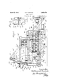
BEAN GRADER Filed July 15, 1926 2 Sheets-Sheet 2 Patented Apr. 12, 1932 WILLIAM unscnnnzor vALPARAIso, INDIANA BEAN GRADER Application filed July 15,
This invention relates to a bean grader, and has to do particularly with an improved type of grader whereby string'beans and the like may be mechanically separated and graded into a number of sizes preparatory to canning.
The bean industry at the present time employs mechanical devices from the time of the planting of the beans to the marketing thereof. Marketing is either in bulkor in a preserved form, such as canned. The present invention perhaps is of particular interest where the beans are to be used forcanning. V a 5 When the beans are harvested by machin ery, .as is usually the practice in large acreages, there are many sizes of beans gathered, from the smallest to the largest, and mixed or therewith are portions of vines, leaves, and the like. It has long been the'practice to sep a rate the beans according to sizes, generally two, a grader for this purpose beingshown in my Patent No. 1,295,642, issued February 25, 1919. This patented machine separates the beans into two'sizes and'is of very great utility in the industry.
Recently, however, the canners of beans have demanded that the beans'be graded into I a larger number of sizes or classes, it now being considered preferable to grade the beans into five sizes. The sizes are numbered l'to 5, the number 1 size being the smallest, and
the number 5 size the largest. e
It is the object of the present invention to provide a machine whereby toseparate string beans in respect to the greater number of sizes as desired by the canners. i
A further object is the production of a machine which will receive string beans as they come from a harvesting machine, remove all foreign matter therefrom, and finally mechanically grade the beans into the sizes re-' qu red. r
*A machine constructed in accordance with the present invention includes a feed hopper into which the beans are placed and an elevat-' ing belt which receives the beans from the hopper and elevates them to a shaker frame, whence they are caused to drop to a feed spout which distributes them'to the grading 1326. Serial No. l22,559. I
parts. Means is provided whereby a draft of air is blown across the beans as they drop from the shaker frame,-where by to remove allforeign matter, such as leaves. The beans being of greater weight than the usual foreign matter encountered are their fall by the blastiof air.-
undisturbed The first grading cylinder which the :beans encounter comprises two parts; .Throughthe first part of this cylinderthe three smallest sizes of beans are discharged, and through the second portion of this member, =the next to the largest size are dischargedi *Thelargest size of'beans are discharged out the end of the cylinder. Both the number"5?" or any larger size, and thenumber 4:size, fallonto separate continuous-conveying belts, from tacles; I W
The three smaller sizes of whence they are deposited into proper-recepbeans a ehute which feeds theminto a second grad ing cylinder, this second grading cylinder also having two sections. Through the first encountered section of the 'cylinder',g.the smallest size beans are discharged',sand as the remaining beans proceed toward the end of the cylinder, they reach the second section of such cylinder, from. whence the number 2 size of beansare discharged; The number ""3 size are conveyed to the the cylinder and are discharged out of such extreme end of end through a spout provided for the purpose. Thethree sizes of beans separated .by the second cylinder drop onto separate con-o tinuous conveyor belts, and are conveyed thereby to properly placed receptacles.
-The graderis'builtintwo units of. se'pa rators, or in tandem, both'units being supplied from the same hopper and belt elevator, the beans being-divided by the distributing spout referred to above, whereby they are fed in substantially equal q two units.
uantities to the The invention will bemore fullyundere stood by the following detailed description taken with the accompanying drawings,
wherein Figure l a side elevation of a bean grader constructed in accor present lnventlon;
dance with the I capacity of the belt as a carrier.
Figure 2 is an end elevation of the same machine looking from the left-hand side of Figure 1 and Figure 3 is an enlarged view of the shaker and distributing spout, and shows the manner in which foreign matter is removed from the beans. I
F ig-ure 4 is a side elevation of'the feeding means as an extension of the view of Figure 1.
In the description which follows like reference characters are usedthroughoutto designate similar members. I
Although I have shown a great many details of a machine which embodies the invention, I have not gone into great'length concerning some of the structural features which ,are purely matters of ordinary mechanical skill, and which if described, would not make the disclosure anymore clear, but onthe con- .trary would tend to obscure by voluminous discussion of unessential matters the description of the actual invention. 7
In: the interest-of clearness, I will first describe the main portions of the mechanism, 25
referring thereto in the orderin which the beans reachthe same. I will not refer in detail to the manneriof driving the different members until. the latter part of the description,and-when describing the motive means I shall proceed from'the source of power.
As Figure 2 shows, the machine is made in two unitsin tandem wh1ch I designate A and 'B, both of-said units being practically identical. For the sake of brevity, therefore, -'I
' will describe the machine generallyv asif it constituted only a single unit.
Beans toybe graded are preliminarily ,placed' in a;hopper 10 .(Figure 1) supported bya bearing 11 at one end, thereof and a pair of travfelersl2 at-theother end thereof. Said hopper 10 is providedwith a continuous gear 13 which is connected bymeans of-a chain 14 with a gear 14 keyed to a'shaft 15'. v
, The hopper 10 is open at each end. Beans are fed in theopening at the right-hand. side (Figure 4) designated =16, and are carried forward (to the'left, Figure 1) by a: feeding baflle .17. The beans are thus deposit-ed on a-continuous traveling feeder belt 20, moving over pulleys 21 and 22. Asprocket gear 23 is secured: integrally with said pulley 22 and is linked with agear 24 by a chain 25. Cleats I20"m 'ay be provided on the belt20 to pro- ,vide shelves or ridges to preventthe'beans from slipping therefrom andtoxincrease the by-gear 33, chain 34, andgear 3 5, the gear'35 being. designed to rotatewith the pulley 22.
After the beans are shaken rfromshaker from the same source of power, but otherwise entirely separate.
The grading cylinder 38 may be constructed in any proper manner, but I prefer to employ substantially the same construction as shown in. my Patent Number 1,295,642, referred to above. I have not shown the gradingcylinder in'detail because it can be readily understood from an inspection of the drawings taken into consideration-with the patent referred to above.
. The usual openings, of course, are provided in the grading cylinder 38, whereby beans of a certain size are-permitted to drop through, while beans of a larger size are retained with in the cylinder. Ihave designed the portion 38a so that the three smaller sizes, numbered 1, 2., and 3, will be discharged therethrough into a feed spout .40. The two larger sizes, 4 and 5, are carried-over into the portion 38b, and this portion of the-grading cylinder is so designed that the smaller'of these two sizes, namely, the number 4 size, will be permitted'todrop therethrough, while the larger size-namely, the. number 5 size, are carried to the end of the cylinder '38 and discharged out through the chute 41. The number 4 size beans discharged through the mesh of the section 386 are deposited onto a continuous conveyor belt 42, while the number 5" size are deposited onto a conveyor belt '43.
I contemplate any suitable means for causing the-beans-to be carried from end'to end ofthe grading cylinder. For-instance,
or employ a feeding bafl'le, depending on the specific construction employed. -l/Vlie1'e I employ a' cylinder of the usual form, it is probably best to placethe rings on a bias.
From the feed spout40, the smaller sizes of beans'are fedinto a second gradingcylinder 45, which cylinder 45 also has two sections,
these being-designated45a and 45b. 'T'he section 45a -is constructed so that only the smallest'sizes of beans, the number l-size, pass through the meshthereof. The section 456 is arranged so that the number 2 size beans will pass therethrough, while the number ;3-size beans are carried 'tothe end of the cylinder to be discharged out a dischute 36, the open end of an air conduit is disposed, said conduit 55 communicating directly with a fanning mill 56. The fanning mill 56 contains a fan 57 secured on a shaft 58, for providing an outward flow of air at the mouth of conduit 55.
It will be thus seen that a blast of air is directed through the beans as they fall from the shaker frame 26. The beans being heavy are slightly affected by the blast, but portions of vine and other foreign matter which are lighter than the beans, will be blown away, leaving only the beans to reach the chute 36.
An examination of the instrumentality, as illustrated, will show that there are a large number of moving parts to the machine. I contemplate driving all of these parts in an improved and convenient manner. In the embodiment of the device shown in the drawings, the drive is through a pulley 60. All
mounted on the same shaft with travelers and which serve to drive the grading cylinder 45.
One of the sprocket gears 63 is engaged by a chain 66 which communicates with a sprocket gear 67 on an upper shaft 68. The upper shaft 68 is provided with the same species of bevel gearing as has just been de scribed communicating with the same type of travelers and drives the grading cylinder 38 in the same manner as set forth in connection with the grading cylinder 45.
The feed chute 36, the function of which has been described above, is mounted on a vertical support 70, which is pivoted at 71. To facilitate action of the feed chute 36, I provide an arrangement whereby it'may be agitated, and such arrangement includes a crank arm 7 2 secured by means of a pivot 73 at the bottom of said vertical support 70.
The crank arm 72 is pivotally secured to a crank 1 7 4, which turns integrally with a sprocket gear 75 mounted on a short shaft 76. The sprocket 75 is driven by a sprocket chain 77 and a small sprocket gear 78 secured on a stub shaft driven from the main transverse shaft61.
As pointed out in the; preliminary part of this specification, the two units of the machine are substantially identical.
Obviously, therefore, unit A has ashaft which I des-' which shaft 68 is identical in its function a with the shaft 68 previously described in connection with the unit B.
At the end of said shaft 68 is provided a sprocket gear'80 which drives a chain 81,.
which in turn drives an upper sprocket gear 82 keyed to the transverse shaft 24 previously referred to.. The shaft 24 is journalled in any suitable bearings and-is provided with a sprocket gear 85-at the end thereof, which sprocket gear 85 drives the sprocket chain 25.
Through this mechanism 1t 18 obvious that the conveyorbelt 2O willbe actuated in accordance vwithiits function. The pulley 22 H being driven in the manner described, it is obvious that the mechanism previously (le scribed in connection with the shaker frame 26 will produce a longitudinalreciprocation of this member. 7
The lower right-hand bevel gear 64, instead of havingth-e usual short stub shaftwhich is shown in the remaining positions, is provided with an elongated shaft (Figure 1) indicatedwby the reference character 90. shaft, through suitable gearing indicated at 91, drives the longitudinal shaft 15 which has been previously referred to. Through the shaft 15 by suitable chains and associated gearing, which I designate for purposes of identification by the numbers 95 to 99,inclu- This sive, the several conveyor belts designated 50, 42, 43, 51, and 52 respectively,are driven.
Rotation of the'shaft 15 also results in a ro- I tary motion of the hopper 10, the associated gearing having been previously described.
The operation of the machine is as follows.
Beans to be graded areplaced in the hopper 10, where they are agitated and carried towardly and upwardly at a uniform speedand" drops them ontothe-shakerframe 26. From the shaker frame 26 they drop to the feed chute .36, and while falling a blast of air from the funnel 55 passes through the beans whereby all foreign matter, such" as leaves and thelike, is removed. The beans are furm -bf cylinder 38, the three smaller sizes are discharged through' the suitably arranged mesh and the balance of the beans are carriedon toith'e section 386. At38b the number 4: size of beans drop onto. the belt 42,
whence they are conveyed to" a suitable recep- -through section 38a, they are conveyed by the tacle, while the number 5 size of beans are discharged out through: discharge chute 41 and droppedonto the conveyor 43.-
lVhen the three smaller sizes of beans drop feed spout 40 to the grading cylinder 45, whence through the same general arrangement as in the grading cylinder 38 the number fl size beans are discharged through the portion 45a and dropped onto the conveyor belt 50. The number 2 size beans are discharged through the section 45?) and dropped onto the conveyor 41, while the number 3 size of beans, the largest'size'of beans to enter the cylinder 45, is discharged through the discharge chute 46 anddropped onto the conveyor belt 52. It is obvious that any usual for-mof container may be provided to receive the beans as they are dropped from the individual conveyor bel in accordance with the scope of the appended Although for purposes of description many 7 features-of the machine embodying the present invention have been referred to somewhat lelism,.:a conveyor feeding beans continuously to said unit,'a distributor comprising a trough adapted to receive beans from said conveyor and discharge them from its ends,
and means for oscillating said trough in' timed relation with themovement of said conveyer to discharge beans alternately at its opposite ends and into diflterent series of screens. 7
4; A bean cleansing instrumentality com-: prising a conveyor for distributing'beans over awide flat surface during which the beans are generally separated one from another and from the end of which conveyor the V beans are discharged by gravity, a shaker with an arcuate top surface and adapted to movezt-ransversely of said conveyor, said conveyor being adapted to discharge its stream of beans at or upon the crown of said shaker, means for oscillating said shaker beneath and across the end of said conveyor, and a blower for forcing a blast of air through said stream .of beans while falling from said conveyor to said shaker.
WV-ILLIAM E. URSCHEL.
T in detail, it is obvious that I do not limit my-; *self to the precise form illustrated-and described, the invention being restricted only claims;
I claim: v
1. "A'bean' grader-comprising a unit having as a part thereof a number of like series of s'creens of different sizes for dividing beans into'a plurality of classes, a conveyer feeding beans continuously to said unit, and
a distributor timedfor movement with said conveyer for diverting the beans from said conveyor to each series of screensone at a time periodically.
2. Abean grader comprising a unit having as a part thereof two like series of rotatable-screens of dilferent sizes for dividing beans into different classes, a conveyor feeding beans continuously to said unit, and a distributor arranged for movement with said conveyeradapted todivert beans alternately f to'each series of screens;
3. A'bean grader comprising a umt having as a part thereof two like serles'of rotatable screens of different size for dividing beans into difie'rent classes and arranged in pa-ral-
Priority Applications (1)
| Application Number | Priority Date | Filing Date | Title |
|---|---|---|---|
| US122559A US1853475A (en) | 1926-07-15 | 1926-07-15 | Bean grader |
Applications Claiming Priority (1)
| Application Number | Priority Date | Filing Date | Title |
|---|---|---|---|
| US122559A US1853475A (en) | 1926-07-15 | 1926-07-15 | Bean grader |
Publications (1)
| Publication Number | Publication Date |
|---|---|
| US1853475A true US1853475A (en) | 1932-04-12 |
Family
ID=22403415
Family Applications (1)
| Application Number | Title | Priority Date | Filing Date |
|---|---|---|---|
| US122559A Expired - Lifetime US1853475A (en) | 1926-07-15 | 1926-07-15 | Bean grader |
Country Status (1)
| Country | Link |
|---|---|
| US (1) | US1853475A (en) |
-
1926
- 1926-07-15 US US122559A patent/US1853475A/en not_active Expired - Lifetime
Similar Documents
| Publication | Publication Date | Title |
|---|---|---|
| US2003097A (en) | Fruit sizer | |
| US2386579A (en) | Grading machine | |
| KR101643117B1 (en) | Chili-pepper harvester | |
| US1853475A (en) | Bean grader | |
| US1895268A (en) | Leaf catcher for beet dumps, etc. | |
| US2395350A (en) | Planter | |
| US2367757A (en) | Fruit feeding device | |
| US1706734A (en) | Fruit-grading machine | |
| US2084935A (en) | Viner | |
| US3682303A (en) | Machine for continuously removing over-sized undesirable material from crop material mixtures | |
| US2209268A (en) | Stone picker for self-feeders of threshing machines | |
| US2376128A (en) | Pocket trommel | |
| USRE17769E (en) | Botabt dispensing bin | |
| US1609442A (en) | Potato and onion grader | |
| US2313051A (en) | Fruit handling equipment | |
| US1641492A (en) | Potato picker, cleaner, sorter, and bagger | |
| US1379715A (en) | Vegetable-grader | |
| US1513482A (en) | Pneumatic cleaner for beans and the like | |
| US1771996A (en) | Pea-grading machine | |
| US1343586A (en) | Potato-picker | |
| US3176737A (en) | Tung nut huller | |
| US1509216A (en) | Fruit-grading machine | |
| US1733757A (en) | Machine for grading globular articles | |
| US1304719A (en) | Machine for preparing vegetables | |
| US1717748A (en) | Grain separator |