US1853440A - Lock washer - Google Patents
Lock washer Download PDFInfo
- Publication number
- US1853440A US1853440A US511896A US51189631A US1853440A US 1853440 A US1853440 A US 1853440A US 511896 A US511896 A US 511896A US 51189631 A US51189631 A US 51189631A US 1853440 A US1853440 A US 1853440A
- Authority
- US
- United States
- Prior art keywords
- washer
- bolt
- lock washer
- inner edge
- nut
- Prior art date
- Legal status (The legal status is an assumption and is not a legal conclusion. Google has not performed a legal analysis and makes no representation as to the accuracy of the status listed.)
- Expired - Lifetime
Links
- 239000000314 lubricant Substances 0.000 description 11
- 238000010276 construction Methods 0.000 description 5
- 230000001050 lubricating effect Effects 0.000 description 4
- 239000003921 oil Substances 0.000 description 3
- 230000015572 biosynthetic process Effects 0.000 description 2
- 230000008602 contraction Effects 0.000 description 2
- 238000005755 formation reaction Methods 0.000 description 2
- 238000000034 method Methods 0.000 description 2
- 244000007853 Sarothamnus scoparius Species 0.000 description 1
- 230000006978 adaptation Effects 0.000 description 1
- 239000002826 coolant Substances 0.000 description 1
- 238000001816 cooling Methods 0.000 description 1
- 238000005260 corrosion Methods 0.000 description 1
- 230000007797 corrosion Effects 0.000 description 1
- 239000000295 fuel oil Substances 0.000 description 1
- 239000004519 grease Substances 0.000 description 1
- 238000005461 lubrication Methods 0.000 description 1
- 239000002184 metal Substances 0.000 description 1
- 230000035515 penetration Effects 0.000 description 1
- 239000007787 solid Substances 0.000 description 1
- 238000005496 tempering Methods 0.000 description 1
Images
Classifications
-
- F—MECHANICAL ENGINEERING; LIGHTING; HEATING; WEAPONS; BLASTING
- F16—ENGINEERING ELEMENTS AND UNITS; GENERAL MEASURES FOR PRODUCING AND MAINTAINING EFFECTIVE FUNCTIONING OF MACHINES OR INSTALLATIONS; THERMAL INSULATION IN GENERAL
- F16B—DEVICES FOR FASTENING OR SECURING CONSTRUCTIONAL ELEMENTS OR MACHINE PARTS TOGETHER, e.g. NAILS, BOLTS, CIRCLIPS, CLAMPS, CLIPS OR WEDGES; JOINTS OR JOINTING
- F16B39/00—Locking of screws, bolts or nuts
- F16B39/22—Locking of screws, bolts or nuts in which the locking takes place during screwing down or tightening
- F16B39/24—Locking of screws, bolts or nuts in which the locking takes place during screwing down or tightening by means of washers, spring washers, or resilient plates that lock against the object
-
- Y—GENERAL TAGGING OF NEW TECHNOLOGICAL DEVELOPMENTS; GENERAL TAGGING OF CROSS-SECTIONAL TECHNOLOGIES SPANNING OVER SEVERAL SECTIONS OF THE IPC; TECHNICAL SUBJECTS COVERED BY FORMER USPC CROSS-REFERENCE ART COLLECTIONS [XRACs] AND DIGESTS
- Y10—TECHNICAL SUBJECTS COVERED BY FORMER USPC
- Y10S—TECHNICAL SUBJECTS COVERED BY FORMER USPC CROSS-REFERENCE ART COLLECTIONS [XRACs] AND DIGESTS
- Y10S411/00—Expanded, threaded, driven, headed, tool-deformed, or locked-threaded fastener
- Y10S411/955—Locked bolthead or nut
- Y10S411/956—Automatic base clutch
- Y10S411/957—Biting tooth
- Y10S411/958—Coiled washer
Definitions
- My invention relates to lock washers, but more particularly has reference to spring washers that are segments of a helixand are used in connection with bolts and nuts for the purpose of resiliently securing the splice- ,bars to the meeting ends of railroad rails.
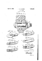
- Figure 1 is a broken sectional elevation showing the assembly or" the splice-bars, rail web, bolt, lock washer and nut, the inner edge of the washershowing one form of my invention
- I j Figure 2 s an elevation of aspring washer having a groove formedthroughout the H inner edge, such as is shownat Figure 1,
- FIG. 3 is a section, at the line 3-3 of Figure 2, 7
- Fi ureset and 5 are viewssirnilar to Figure cant containing grooves.
- Figure 6 is a broken elevation showing the inner edge of a lock washer with vertically disposed lubricant containing grooves
- the lubricant container is a circular groove 1 formed in the inner'edge 2 of the lock washer 3, while in Figure 4 an angular groove 4 is shown in said edge.
- the inner edge of the washer is concaved as shown at 5.
- spaced vertical lubricant containing grooves 6 are shown, while in Figure 7, depressions or cups 7 are formed in suitable locations in the inner edge of the washer.
- the invention is not limited to any special lubricant containing formations, the gist of this invention residing in the broad idea of providing a lock washer with lubricant containing parts that will automatically function to lubricate the threads of the bolt, and right in this connection I desire to state that, since, after the suggestions and manifest deduction afforded by my invention, it is quite within the range of mechanical skill to construct a washer especially adapted for the automatic lubrication of the bolt threads, I do not wish to be limited to any special formationor adaptation of a lock washer for the purpose of automatically lubricating parts that are associated with such washer in what are commonly known as track joints.
- the cooling medium will act more uniformly and will result in a better job of hardening and a more uniformly hardened structure.
- INha-tis claimed is i 1.
- a lubricating device the combination with a splice bar, track bolt and nut, of .a spring washer around said bolt and interaposed between said bar and nut andhaving in .its inner edge a lubricant container.
- a construction as in claim 1 further distinguished in that said containerconsists of a groove formed lengthwise of said edge.
- a lubricating device for a structure for railroad track oints comprising parts to be clamped, a threaded bolt extending through the railroad rail and said parts, and
- a nut driven on said belt a spring washer surrounding said bolt beneath said nut and carrying lubricant containing parts that are freely-exposed to said bolts, whereby the expansion and contraction of said washer will lubricate the threads of the bolts.
Landscapes
- Engineering & Computer Science (AREA)
- General Engineering & Computer Science (AREA)
- Mechanical Engineering (AREA)
- Lubricants (AREA)
Description
April 12, 1932. c, H LOUTREL 1,853,440
LOCK WASHER Filed Jan. 28, 1931 ECG-.11...
Patented Apr. 12, 1932 UNITED STATES PATENT "OFFICE I CYRUS H. LOUTREL, OF SOUTH ORANGE, NEW JERSEY,.ASSIGNOR TO THE.NATIONAL LOCK WASHER COMPANY, OF NEWARK, NEW JERSEY, ACORPORATION OFITEW JERSEY LOCK WASHER.
Application filed January 28, 1931. vSt arialtl'o. 511,896.
My invention relates to lock washers, but more particularly has reference to spring washers that are segments of a helixand are used in connection with bolts and nuts for the purpose of resiliently securing the splice- ,bars to the meeting ends of railroad rails.
The use of spring washers around the bolts and interposed between such bars and the securing nuts is so Well understood as to require no description or special comment herein, but difficulty is experienced in greasing or oiling the bolts and nuts so that they will not become corroded.
It is a common practice to essay this oiling or greasing or" the bolts and nuts, and, in fact, the entire rail joint, by means of an oiling machine running on the rails themselves, but when such a machine is not available, men walk along the track carrying pails of oil and brushes or brooms which are dipped in the oil and splashed against the joint, the nuts and bolts. In either of these processes it is unlikely that the oil would percolate between the washer and the bolt or between the washer and the splice-bar and run into the threads of the bolt. Therefore there is very apt to be an area of bolt threads that is not lubricated and is subject to corrosion.
It is the object of this invention to so equip the lock washer that, as the latter expands or contracts, due to heavy loads passing over the joint or to changes of tempera ture, the threads of the bolt will be lubricated.
This result is brought about by the formation of grooves or pockets within the inner edge of the washer, which, of course, is the edge that is adjacent the bolt, and filling these grooves or pockets with heavy oil or grease, or other suitable lubricant, so that the expansion or contraction of the washer above referred to, will cause the lubricant to flow sufiiciently so as to be transferred to the threads of the bolt.
In the accompanying drawings, which must be taken into consideration as a part of this description,
Figure 1 is a broken sectional elevation showing the assembly or" the splice-bars, rail web, bolt, lock washer and nut, the inner edge of the washershowing one form of my invention, I j Figure 2 s an elevation of aspring washer having a groove formedthroughout the H inner edge, such as is shownatFigure 1,
Figure 3 is a section, at the line 3-3 of Figure 2, 7
Fi ureset and 5 are viewssirnilar to Figure cant containing grooves.
Figure 6 is a broken elevation showing the inner edge of a lock washer with vertically disposed lubricant containing grooves, and
3, but showing modified forms of the lubri- Figure 7 is a view similar to Figure 6, but
showingseparate lubricant containing recesses or depressions that are not in the form of a groove. x
Similar numerals of reference will be used to denote like the drawings; In the construction shown at Figures 1, 2 and 3, the lubricant container is a circular groove 1 formed in the inner'edge 2 of the lock washer 3, while inFigure 4 an angular groove 4 is shown in said edge. In Figure 5 the inner edge of the washer is concaved as shown at 5. In Figure 6 spaced vertical lubricant containing grooves 6 are shown, while in Figure 7, depressions or cups 7 are formed in suitable locations in the inner edge of the washer.
, Thus it'will be noted that the invention is not limited to any special lubricant containing formations, the gist of this invention residing in the broad idea of providing a lock washer with lubricant containing parts that will automatically function to lubricate the threads of the bolt, and right in this connection I desire to state that, since, after the suggestions and manifest deduction afforded by my invention, it is quite within the range of mechanical skill to construct a washer especially adapted for the automatic lubrication of the bolt threads, I do not wish to be limited to any special formationor adaptation of a lock washer for the purpose of automatically lubricating parts that are associated with such washer in what are commonly known as track joints.
In the construction shown Figures 1, 2 and parts in theseveral figures of j 3 are preferred, since it is quite clear that less internal stress will be set up within the section itself if the inner edge of the washer is grooved in the center of its thickness.
31 The improvement hereinbefore described,
is an advantage so far as the actual construction of the washer is concerned, since the tempering process, it is undoubtedly true that the outer walls become heated first, and
1 theheat then progresses to the center of the I mass, and 'fagr'oove, such as is shown in Figures 1, 2 and 3, is introduced in the mass, the heat will be enabled to reach the center of the mass with more rapidity than would be the case were there solid metal where the grooves exists. In other words, there would Y be less delay in the penetration of the entire mass by the heat. It is believed that this is the first time that such a form of lock washer has been proposed in a track nutconstruction {to bring about the desired result.
' Also, it is desired that the cooling of the washers after they have been heated be effectedlas uniformly and promptly as possible, 7
and therefore, in the present structure, the cooling medium will act more uniformly and will result in a better job of hardening and a more uniformly hardened structure.
INha-tis claimed is i 1. In a lubricating device the combination with a splice bar, track bolt and nut, of .a spring washer around said bolt and interaposed between said bar and nut andhaving in .its inner edge a lubricant container.
2. A construction as in claim 1 further distinguished in that said containerconsists of a groove formed lengthwise of said edge.
3. A construction as in claim 1 with the ad- :dition that said container extends substan- 40 tially throughout the length of said edge and is in the central portion of the thickness of said edge.
4. In a lubricating device the combination with a threaded bolt, a nut driven on said-bolt and an object to be clamped by the action of said nut, of a spring washer surrounding'said bolt and confined between said obj e-ct and nut, and a lubricant carried by the inner edge of said washer and freely exposed adjacent said bolt.
5. In a lubricating device for a structure for railroad track oints comprising parts to be clamped, a threaded bolt extending through the railroad rail and said parts, and
a nut driven on said belt, a spring washer surrounding said bolt beneath said nut and carrying lubricant containing parts that are freely-exposed to said bolts, whereby the expansion and contraction of said washer will lubricate the threads of the bolts.
In testimony whereof I affix my signature hereto.
. 1. "CYRUS I-I. LOUTREL.
Priority Applications (1)
| Application Number | Priority Date | Filing Date | Title |
|---|---|---|---|
| US511896A US1853440A (en) | 1931-01-28 | 1931-01-28 | Lock washer |
Applications Claiming Priority (1)
| Application Number | Priority Date | Filing Date | Title |
|---|---|---|---|
| US511896A US1853440A (en) | 1931-01-28 | 1931-01-28 | Lock washer |
Publications (1)
| Publication Number | Publication Date |
|---|---|
| US1853440A true US1853440A (en) | 1932-04-12 |
Family
ID=24036899
Family Applications (1)
| Application Number | Title | Priority Date | Filing Date |
|---|---|---|---|
| US511896A Expired - Lifetime US1853440A (en) | 1931-01-28 | 1931-01-28 | Lock washer |
Country Status (1)
| Country | Link |
|---|---|
| US (1) | US1853440A (en) |
-
1931
- 1931-01-28 US US511896A patent/US1853440A/en not_active Expired - Lifetime
Similar Documents
| Publication | Publication Date | Title |
|---|---|---|
| US1853440A (en) | Lock washer | |
| Sawamura et al. | Measurement of friction coefficient by backward extrusion with rotating tool under severe forming conditions | |
| US1995548A (en) | Grease retaining bushing | |
| US2440812A (en) | Crankshaft lubricant purifying means | |
| US1518960A (en) | Sucker-rod joint | |
| BR112018000272B1 (en) | PROCESS FOR MANUFACTURING WEAR-RESISTANT THREADED TUBULAR COMPONENTS | |
| US1819784A (en) | Connecting rod structure | |
| CN216666193U (en) | Improved generation lock nut | |
| Hughes | A practical application of the flash-temperature hypothesis to gear lubrication | |
| US1209537A (en) | Ball-bearing. | |
| US1385968A (en) | Lubricating device for chain-pins | |
| US2091906A (en) | Tool joint | |
| US2134508A (en) | Universal joint | |
| US1394597A (en) | Means for lubricating rail-joints | |
| US1042543A (en) | Connecting-rod for engines. | |
| US2044375A (en) | Lubricator adapter for springs | |
| DE939667C (en) | Plain bearings for shafts of machines driven by electric motors for the conveyance of liquids or moist gases | |
| US2150893A (en) | Journal box | |
| Shipley | Gear and Spline Testing | |
| DE2419500A1 (en) | COVER FOR IMPROVING THE RUN-IN AND EMERGENCY RUNNING BEHAVIOR OF SLIDING FRICTION SUBJECT TO MACHINE PARTS | |
| US20150308506A1 (en) | Device to retain lubricant in a lubricating assembly and implementation thereof | |
| US1135515A (en) | Compound bolt. | |
| US2139738A (en) | Means for lubricating springs | |
| US778848A (en) | Swab-holder. | |
| RU2632386C1 (en) | Gear wheel |