US1853433A - Sleeve valve engine - Google Patents
Sleeve valve engine Download PDFInfo
- Publication number
- US1853433A US1853433A US237955A US23795527A US1853433A US 1853433 A US1853433 A US 1853433A US 237955 A US237955 A US 237955A US 23795527 A US23795527 A US 23795527A US 1853433 A US1853433 A US 1853433A
- Authority
- US
- United States
- Prior art keywords
- cylinder
- sleeve
- opening
- wall
- openings
- Prior art date
- Legal status (The legal status is an assumption and is not a legal conclusion. Google has not performed a legal analysis and makes no representation as to the accuracy of the status listed.)
- Expired - Lifetime
Links
Images
Classifications
-
- F—MECHANICAL ENGINEERING; LIGHTING; HEATING; WEAPONS; BLASTING
- F01—MACHINES OR ENGINES IN GENERAL; ENGINE PLANTS IN GENERAL; STEAM ENGINES
- F01L—CYCLICALLY OPERATING VALVES FOR MACHINES OR ENGINES
- F01L5/00—Slide valve-gear or valve-arrangements
- F01L5/04—Slide valve-gear or valve-arrangements with cylindrical, sleeve, or part-annularly shaped valves
- F01L5/06—Slide valve-gear or valve-arrangements with cylindrical, sleeve, or part-annularly shaped valves surrounding working cylinder or piston
- F01L5/08—Arrangements with several movements or several valves, e.g. one valve inside the other
- F01L5/10—Arrangements with several movements or several valves, e.g. one valve inside the other with reciprocating and other movements of the same valve
Definitions
- This invention relates to internal combustion engines and particularly internal combustion engines of the sleeve valve type and it is an object of the invention to; provide a more economical and better operat ng englne.
- I Figure 1 is a view mainly in cross sect on through a cylinder of an internal combustlon engine of the Vauxhall Burt sleeve valve type.
- re 2 is a fragmentary section on the i line 22 of Figure 1.-
- the cylinder head is provided with a water jacket 12 which is secured to the block by bolts, such as 13. Water enters the jacket through the D-shaped channel 14, flows through the opening 15 into the funnel 16,
- the sleeve 11 is given a reciprocatory, combined translational and rotational motion by the pin 18 and in the course of its movement brings the sleeve intake ports (two of which,
- the cylinder wall 10 is
- the sleeve llis provided with four lozenge-shaped openings 27 whichare adapted to register with theopenings 25, in the cylinder wall to admit air to the cylinder at the end of the intake stroke, as shown in' Figures 1 and 2. It is to be noted, as shown in Figure 1, that at this time the top of the piston is below the groove 26 .and, the openings 25 and 27being in registration,air will enter the cylinder from the spaces 28 and 29, which are in communication with the atmosphere, due to the difi'erence in pressure in the cylinder and outside. Admission of air to the cylinder at the end of the intake strokeproduces what is known as a stratified'combustion mixture which tends to make the engine, operate more economically. 1
- the openings 27 in the sleeve may be eliminated if desired. If this is done, no air will be admitted to the cylinder through the openings 25 and the remaining structure (the groove 26 and the openings 25 in the cylinder) will. function merely to prevent oil pumping. V Furthermore,the openings 25 and the openings '27, or the openings 27'and the groove 26may be eliminated. "In the former case the groove 26 will operate to hold oil for lubricating the sleeve: In the latter case the openings 25 will operate to'preventpumpingof oil.” 7
- stratified combustion mixture including, a
- an internal combustion engine which includes a cylinder, a sleeve valve slidable in the cylinder, and a piston slidable in the sleeve, means for preventing oil pumping and for producing a Stratified combustion mixture including,'a circumferential groove in the" inner wall of the cylinder so located that it'will be uncovered by the piston near the, end of the suction stroke, an opening in the groove leading-to the outside of the cylinder wall, andan opening in the sleeve adaptedto: register withthe opening in'the cylinder wall near the'end of the suction stroke.
- an internal combustion engine which includes a cylinder and a piston slidable-in the cylinder, means for preventing oil pumping and for producing a stratified combustion mixture including an opening in the cylinder wall through which excess lubricant is adapted to. be discharged fromfthe cylinder, which includes a cylinder, a sleeve valve slidable in the cylinder, and a piston slidable in the sleeve, an opening in the cylinder wall through which excess lubricant is adapted to be discharged from the cylinder, and which is so.
- an internal combustion engine which includes a cylinder, a valve slidable on a wall of the cylinder, and a piston slidable in the cylinder, means for preventing oil pumping and for producing a stratified combustion mixture including a circumferential groove.
Description
April 12, 1932.
C. E. KING SLEEVE VALVE ENGINE Filed-Dec. 5', 1927 Patented Apr. 12, 1932 {UNITED STATES PATENT .JOFFICE cLA ENoE EVELYN KING, E HARPENDEN, ENGLAND, AssIGNoR To GENERAL Mo oRs CORPORATION, O DETROIT, MICHIGAN, A coRro A IoN 0E DELAWARE sL'EEvE vALvE ENGINE Application filed December 5, 1927. Serial No. 237,955.
- This invention relates to internal combustion engines and particularly internal combustion engines of the sleeve valve type and it is an object of the invention to; provide a more economical and better operat ng englne.
It is another object of the invention to provide means for preventing oil pumping in an engine;
It is another object of the invention to pro vide means for preventing oil pumpingcombined with means for producing a Stratified combustion mixture in an internal combustion engine.
Other objects of the invention Wlll appear in the course of the following specification in which the embodiment of my invention which is shown in the accompanying drawings is described. y
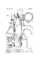
In the drawings: I Figure 1 is a view mainly in cross sect on through a cylinder of an internal combustlon engine of the Vauxhall Burt sleeve valve type.
Figu
re 2 is a fragmentary section on the i line 22 of Figure 1.-
The cylinder head is provided with a water jacket 12 which is secured to the block by bolts, such as 13. Water enters the jacket through the D-shaped channel 14, flows through the opening 15 into the funnel 16,
through the funnelinto the depending portion 9 of the cylinder head and then into chan-' nel 17, whence it is returned to the radiator.
The sleeve 11 is given a reciprocatory, combined translational and rotational motion by the pin 18 and in the course of its movement brings the sleeve intake ports (two of which,
19 and 20, are shown) and the sleeve exhaust ports (one of which, 21, is shown) into registration with the proper cylinder intake ports (one of which, 22, is shown) and cylinder exhaust ports (not shown) at'the proper times to allow intake or exhaust.
The cylinder wall 10, it will benoted, is
provided with four lozengeshaped openings 25 in a circumferential groove 26 near its lower end. The excess lubricating oil carried by the sleeve runs'into the groove 26, thence through the openings25 into the spaces 28 and 29 and from these spaces through -communicating openings one "of which is indicated at 30 to the crankcase and thus oil pumpingis prevented.
The sleeve llis provided with four lozenge-shaped openings 27 whichare adapted to register with theopenings 25, in the cylinder wall to admit air to the cylinder at the end of the intake stroke, as shown in'Figures 1 and 2. It is to be noted, as shown in Figure 1, that at this time the top of the piston is below the groove 26 .and, the openings 25 and 27being in registration,air will enter the cylinder from the spaces 28 and 29, which are in communication with the atmosphere, due to the difi'erence in pressure in the cylinder and outside. Admission of air to the cylinder at the end of the intake strokeproduces what is known as a stratified'combustion mixture which tends to make the engine, operate more economically. 1
The openings 27 in the sleeve may be eliminated if desired. If this is done, no air will be admitted to the cylinder through the openings 25 and the remaining structure (the groove 26 and the openings 25 in the cylinder) will. function merely to prevent oil pumping. V Furthermore,the openings 25 and the openings '27, or the openings 27'and the groove 26may be eliminated. "In the former case the groove 26 will operate to hold oil for lubricating the sleeve: In the latter case the openings 25 will operate to'preventpumpingof oil." 7
Theprovision of the means for producing a Stratified combustionmixture inthe enginecylinders-is ,not my invention and I, therefore, do not claim this feature, per'se. My-invention resides in the means for preventing oil pumping and the means for per .7 mitting. the return of the lubricating oil to venting oil pumping and for producing a f of the suction stroke. 7 I 7 -6LfIn' an internal combustion engine which side of the cylinder.
stratified combustion mixture including, a
groove in the inner wall of; the cylinder so locatedthat it .will be uncovered by the piston near the end of the suction stroke, and openings in the groove leading to the out- 2. In an internal combustion engine which includes a cylinder, a sleeve valve slidable in the cylinder, and a piston slidable in the sleeve, means for preventing oil pumping and for producing a Stratified combustion mixture including,'a circumferential groove in the" inner wall of the cylinder so located that it'will be uncovered by the piston near the, end of the suction stroke, an opening in the groove leading-to the outside of the cylinder wall, andan opening in the sleeve adaptedto: register withthe opening in'the cylinder wall near the'end of the suction stroke.
3. In an internal combustion engine which includes a cylinder, a sleeve slidable in-the cylinder, and a piston slidable in thesleeve, a. circumferential groovein the inner wall of the cylinder so located that it will be uncovered by the piston near the end of the suction 'stroke, an-opening in .the groove penetrating the cylinder wall, and an opening in -he.sleeve adaptedv to register with the opening in the'cylinder-wall near the end of the suction stroke,
4:. In an internal combustion engine Which includes a cylinder and a piston slidable-in the cylinder, means for preventing oil pumping and for producing a stratified combustion mixture including an opening in the cylinder wall through which excess lubricant is adapted to. be discharged fromfthe cylinder, which includes a cylinder, a sleeve valve slidable in the cylinder, and a piston slidable in the sleeve, an opening in the cylinder wall through which excess lubricant is adapted to be discharged from the cylinder, and which is so. arranged as to prevent the return of the discharged lubricant into the cylinder, and an opening in the sleeve through which excess lubricant may be drained from the piston, andwhich is adapted to register with the opening in the cylinder wall at predetermined intervals,
7. In an internal combustion engine, which includes a cylinder, a valve slidable on a wall of the cylinder, and a piston slidable in the cylinder, means for preventing oil pumping and for producing a stratified combustion mixture including a circumferential groove.
in the inner wall of the cylinder adapted to be uncovered by the pistonnear the end of the of the cylinder, and a piston slidable in the 7 cylinder, means for preventing oil pumping and for producing a stratified combustion mixture including an opening in the cylinder wall through which excess lubricant is adapted to be discharged from the cylinder, which is so arranged as to prevent the return of the discharged lubricant into the cylinder, and
which is' adapted to be uncovered by the piston near the end of-the suction'stroke, and an opening-in the valve adapted to register with the openingin the cylinder wall near the end of the suction stroke.
In testimony whereof I afiix my signature.
0. E. KING.
is so arranged as toprevent the return of discharged lubricant into the-cylinder and which is adapted to'be uncovered by'thepiston near the end of the suction stroke.
i 5. In aninternal combustion engine which includes a cylinder, a sleeve valve slidable in the cylinder, and a piston slidable in the sleeve,means for preventing oil pumping and 7 for producing astratified'combustion mixture including, an-.opening.in the cylinder wall through which excess lubricant is adapted to bedischarged from the cylinder, whichis so arranged as to prevent the returnpfdischarged lubricant into the cylinder, and
whichis adapted to be uncoveredby therpis'ton 1 v near' the end of 'thesuction' stroke,'and an openingin the sleeve adaptedito registerwith' theopening inthe cylinder wall near the end
Priority Applications (1)
| Application Number | Priority Date | Filing Date | Title |
|---|---|---|---|
| US237955A US1853433A (en) | 1927-12-05 | 1927-12-05 | Sleeve valve engine |
Applications Claiming Priority (1)
| Application Number | Priority Date | Filing Date | Title |
|---|---|---|---|
| US237955A US1853433A (en) | 1927-12-05 | 1927-12-05 | Sleeve valve engine |
Publications (1)
| Publication Number | Publication Date |
|---|---|
| US1853433A true US1853433A (en) | 1932-04-12 |
Family
ID=22895920
Family Applications (1)
| Application Number | Title | Priority Date | Filing Date |
|---|---|---|---|
| US237955A Expired - Lifetime US1853433A (en) | 1927-12-05 | 1927-12-05 | Sleeve valve engine |
Country Status (1)
| Country | Link |
|---|---|
| US (1) | US1853433A (en) |
Cited By (1)
| Publication number | Priority date | Publication date | Assignee | Title |
|---|---|---|---|---|
| US2429304A (en) * | 1943-03-11 | 1947-10-21 | Aspin Frank Metcalf | Rotary valve assembly for internalcombustion engines, compressors, and the like |
-
1927
- 1927-12-05 US US237955A patent/US1853433A/en not_active Expired - Lifetime
Cited By (1)
| Publication number | Priority date | Publication date | Assignee | Title |
|---|---|---|---|---|
| US2429304A (en) * | 1943-03-11 | 1947-10-21 | Aspin Frank Metcalf | Rotary valve assembly for internalcombustion engines, compressors, and the like |
Similar Documents
| Publication | Publication Date | Title |
|---|---|---|
| US1527166A (en) | Two-cycle internal-combustion engine | |
| EP1284356A3 (en) | Intake system for an internal combustion engine | |
| US1853433A (en) | Sleeve valve engine | |
| US1550643A (en) | Reciprocatory internal-combustion engine | |
| US1367164A (en) | Crank-case breather for internal-combustion engines | |
| US2639701A (en) | Ventilating system for sealed ignition distributors and engine crankcases | |
| US2722924A (en) | Internal combustion engine | |
| US3241534A (en) | Crankcase vapor recycling system | |
| US1899743A (en) | Slide valve engine | |
| US1090991A (en) | Internal-combustion engine. | |
| US1640958A (en) | Internal-combustion engine | |
| US1652266A (en) | Internal-combustion engine | |
| US1995307A (en) | Internal combustion engine | |
| US2587842A (en) | Rotary valve with liquid fuel injection port | |
| US1371550A (en) | Internal-combustion engine | |
| US891366A (en) | Internal-combustion engine. | |
| US1750733A (en) | Rotary valve mechanism for internal-combustion engines | |
| US2183527A (en) | Internal combustion engine | |
| US1963614A (en) | Internal combustion engine | |
| US1929398A (en) | Oiling system | |
| US1812456A (en) | Internal combustion engine | |
| US1821991A (en) | Oil appliance for sleeve-type of internal-combustion engines | |
| DE353453C (en) | Rotary valve control for six-stroke internal combustion engines | |
| US1745343A (en) | Internal-combustion engine | |
| US1404797A (en) | Lubricating system for internal-combustion engines |