US1853426A - Needle finishing machine - Google Patents
Needle finishing machine Download PDFInfo
- Publication number
- US1853426A US1853426A US482819A US48281930A US1853426A US 1853426 A US1853426 A US 1853426A US 482819 A US482819 A US 482819A US 48281930 A US48281930 A US 48281930A US 1853426 A US1853426 A US 1853426A
- Authority
- US
- United States
- Prior art keywords
- needle
- gripper
- carrier
- wheel
- needles
- Prior art date
- Legal status (The legal status is an assumption and is not a legal conclusion. Google has not performed a legal analysis and makes no representation as to the accuracy of the status listed.)
- Expired - Lifetime
Links
- 238000011282 treatment Methods 0.000 description 33
- 230000033001 locomotion Effects 0.000 description 29
- 238000005498 polishing Methods 0.000 description 14
- 238000010586 diagram Methods 0.000 description 7
- 238000000034 method Methods 0.000 description 7
- 239000004575 stone Substances 0.000 description 7
- 239000000969 carrier Substances 0.000 description 5
- 230000007246 mechanism Effects 0.000 description 5
- 239000010985 leather Substances 0.000 description 3
- 238000010276 construction Methods 0.000 description 2
- 238000006073 displacement reaction Methods 0.000 description 2
- 238000009940 knitting Methods 0.000 description 2
- 238000004519 manufacturing process Methods 0.000 description 2
- 241000282326 Felis catus Species 0.000 description 1
- 238000005452 bending Methods 0.000 description 1
- 230000001680 brushing effect Effects 0.000 description 1
- 238000004140 cleaning Methods 0.000 description 1
- 230000006835 compression Effects 0.000 description 1
- 238000007906 compression Methods 0.000 description 1
- 230000007547 defect Effects 0.000 description 1
- 230000000881 depressing effect Effects 0.000 description 1
- 230000000994 depressogenic effect Effects 0.000 description 1
- 230000000694 effects Effects 0.000 description 1
- 238000000605 extraction Methods 0.000 description 1
- 230000001771 impaired effect Effects 0.000 description 1
- 229940090441 infed Drugs 0.000 description 1
- 238000007689 inspection Methods 0.000 description 1
- 239000000463 material Substances 0.000 description 1
- 230000000153 supplemental effect Effects 0.000 description 1
Images


Classifications
-
- B—PERFORMING OPERATIONS; TRANSPORTING
- B21—MECHANICAL METAL-WORKING WITHOUT ESSENTIALLY REMOVING MATERIAL; PUNCHING METAL
- B21G—MAKING NEEDLES, PINS OR NAILS OF METAL
- B21G1/00—Making needles used for performing operations
- B21G1/12—Securing, cleaning-off burrs, reconditioning polishing, grinding
-
- Y—GENERAL TAGGING OF NEW TECHNOLOGICAL DEVELOPMENTS; GENERAL TAGGING OF CROSS-SECTIONAL TECHNOLOGIES SPANNING OVER SEVERAL SECTIONS OF THE IPC; TECHNICAL SUBJECTS COVERED BY FORMER USPC CROSS-REFERENCE ART COLLECTIONS [XRACs] AND DIGESTS
- Y10—TECHNICAL SUBJECTS COVERED BY FORMER USPC
- Y10T—TECHNICAL SUBJECTS COVERED BY FORMER US CLASSIFICATION
- Y10T29/00—Metal working
- Y10T29/44—Filing
Definitions
- This invention is a novel needle finishing machine, and relates more particularly to the finishing (for example grinding and polishing) of needles of the class having a thread engaging part or spring beard at one end and a butt by which the needle may be held at the other end, although it can be'employed for treating other types andclasses of needles.
- the invention is illustratively shown as applied to thefinishing of the so-called spring beard type of needle commonly used 1n the hosiery knitting machines.
- 1,696,484 of December 25, 1928 shows a machine for manufacturing such knitting needles, and the product of such machine 1s a needle which may be perfected by thefinishing of its various parts and surfaces, and the purpose of the present invention is to afford an efficient automatic machine adapted to perform suitable finishing operations onsuc'h or other needles.
- a further object is to afford such a needle finishing and polishing machinewhioh is capable of rapid operation, so as to give a'lai ge output, and thus minimizethe cost of manufacture,as well as improving the quality of the product; also to complete alldesirable finishing, including the groove or noucat, and'so avoiding supplemental operations.
- the attainment of the objects and advantages referred to the present invention consists in theinovel needle finishing method and machine, and thenovel features of operation, mechanism, combination, arrangement and detail herein illustrated or described.
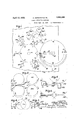
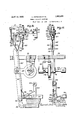
- Fig. 1 is a general diagram in plan view indicating the path of travel of-thesuccessive needles andthe consecutive operations, treatments or stations A to L through which each needle passes, beginning with the infeed and terminating with the delivery.
- Fig. l the portion of the machine nearest to the observer of Fig. lwillbe con- Y sidered as the front of the machine, the infeeding operator standing at the right side the infeed to apply the successive needles to wheel or disk.
- Figure 2 is a similar plan view diagram ina dicating only'the means and mode oftreatment at the station E atwhich the'lateral sides of the first or beard end of'the needle are "rough finished or ground.
- Fig. 3,-in elevation is a diagramof the next succeeding step or operation at station F of finishing or polishing the narrow or top andbottom edges of the beard end of the needle.
- Fig. 4, in elevation is a diagram of the next succeeding step" or operation at station G wherein the:
- Fig. 5 in elevation, is a diagram of the nextsucceeding step or station H in 'which by a brushing action the groove or noucatof the bearded needleiscleaned and V finished.
- Fig.6, in-plan view is a diagram of the'neXt succeeding OPGI'ELlZlOIl or treatment I at station J wherein the butt end ofthe needle is finished at its lateral sides whi'le'hel'd by operation at station K in which the final polishing of the butt end of the. needle is V,
- Fig. 7 is aside view of the particular type oftneedle for. the finishing of which the illustratedv embodiment of theinvention isiparticularly designed, having the beard. and co.- operating noucat at one end of the shank and at the other end a butt vorlateral holding pro jection.
- Fig. 8 is a top plan'view ofthe needleshown in Fig. 7-.
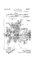
- Fig. 9 is a: general plan view of the machine, with certain parts broken away or omitted for clearness of illustration, the disclosure of this figure corresponding with the plan: view diagram ofFig. 1 in showing the relation of the various operations and de-; vices.
- Fig.10 is a detached perspective view.
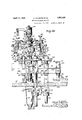
- Fig.- 11- is ageneral front. elevation of the machine with. certain parts omitted and others broken away for better showing ofthe construction. 7
- Fig. 12- is a. right side elevation viewrof the same. 7 I
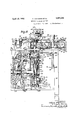
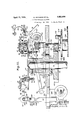
- Fig. 13 is a plan view partly: in horizontal section taken on the plane 1313 of Fig. 12, showing the upper portion of the actuating connectionsofthe machine, including the intermittent drive device giving step by step motions-to the twocarriers.
- Fig. 14 is apl'anview taken partly in hori-' zontal section on'the plane 14-14 of Fig. 12, showing the lower portion of the actuating mechanism. 7 S
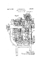
- Fig. 15- is-a vertical. section view'taken on the line 1515'of Fig. 9 and showing the first and fourth operations or treatments performed at opposite sides of. the first rotary carrier, and the: devices and actuating connections therefor.
- Fig. 15 is a detail elevation of a needle leveling contact or device.
- Fig.2 16 is a vertical section taken on the line16 16 of Fig- 9 showing particularly the second operation or treatment, and the device and actuating connections therefor.
- Fig. 17 is an elevation view of the mechanism shown in Fig. 16, looking toward the right sideof Fig. 16.
- Fig. 18 is a vertical section taken on the line -1 818 of Fig; 9 showing particularly the third operation or'treatment, and the: de-
- FIG. 19 is an elevation view of themechanism shown in Fig. 18,'lookingtoward the right side of Fig. 18. I r
- Fig. 20 is an. elevation view partly in vertical section on the line 20-20' of, Fig. 9 showing particularly the'second rotary carrier or turret and its actuating mechanism.
- Fig. 21 is a vertical section on the line 21 21 of Fig.- 9, indicating the relation of the first'and' second carriers. 1 i
- Fig. 22 is a vertical section taken on the line2222 of Fig. 9, indicating the relation between the infeed disk and the first carrier, alsocertain parts of the device for the third operation or treatment, enlarged as compared with Fig- 18.
- Needle finishing method In general the preferred order of steps of operation and treatment of the successive needles 25 may be outlined as follows, with particular referencetothe diagrams, Figs. 1 30 6 and plan view; Fig. 9. An advancing infeed conveyor or wheel 26'is employed, followed by a firstadvancing carrier or rotary turret 27, and a secondsuch carrieror turret 28, by which conveyor and carriers the successive needles 25 are advanced through.- various movements and pauses, including infeed, transfer, adjustment, treatment and outfe'ed or delivery of the completed product.
- the conveyor orinfeed wheel 26' has successive receiving means or slots in'which the needles are successively introduced either manually or by automatic devices; and the infeed position or station may be, for example, at A on Fig.1.
- This infeed member orwheel is arranged to receive and carry a large number of. needles at once, the needles being introduced at the infeed point A. I The travel may bestepby step.
- a contact device or guard 29 acts to readjust the needles in the conveyor if incorrectly positioned.
- the needles are initially positioned in the infeed wheel with their butt endsprojecting peripherally, so that the first carrier grips and takes each needle by its butt end for subsequent trea ment of the beard end.
- the revolving carrier 27 is shown as h aving a set of six such grippers, so that as each needle is advanced from the transfer station C by one gripper the succeeding gripper comes to position to take the next needle. hile the infeed wheel may carry a large number of needles andadvance with small steps the carrier having only a small number of grippers advances with large steps to the successive treatments. From the transfer point C each needle is advanced by its'gripper, while held by its-butt end, andduring this advancing movement a fixed adjusting contact comes into playat point D to reset or level each needle into itscorrect plane of travel if out ofsuch plane.
- the first treatment of the needle is effected, namely afinishing operation at the two lateral sides of the needle.
- This preferably is a rough finishing or grinding operationby a device 31 comprising rollers working successively or simultaneously upon the two sidesof the needle shank as will be described more in detail.
- each needle is brought to the next station F.
- a device 32 comprising apair of finishing'members operates upon the narrow top andbottom edges of the needle including the top of the beard, At
- the third treatment is performed by a device '33, arranged to act upon the ground sides of the needle'to polish them.
- a finishing device 34- acts on top of the needle to give a fourth treatment and clean out and thoroughly finish the groove or noucat.
- a transfer is effected, the exposed beard end of the needle being gripped by one of the grippersmounted at the periphery of the second carrier .28 which also has a step-by-step advancing motion.
- the first carrier is caused to release the needle while the second carrier takes and holds it, following which the second carrier makes an advancing motion 'to station or position J, where the sides of the butt end of theneedle are round by a device 35; after which the next forward shift brings the needle to position K Where the same surfaces are polished by a device 36.
- the gripper may be caused to open and release or deliver the finished needle into a suitable receptacle or device 37, from which theyma-y be removedto boxes or containers for example in batches of one hundred.
- finishing is used in the sense of performing any treatment to complete or correct the needles as to their surfacing, shape or otherwise; the particular finishing operations herein disclosed including difierent' grades of treatment, such. as a preliminary or rough finishing, referred to as grinding, and a final or smooth finishing referred to as polishing.
- the first treatment, performed at station 7 E,' is separately indicated in Fig. 2, and con- 1 sists in a grinding action at the two lateralsides of the beard end of the needle by means of a grinding device or pair of stones 31, which may have a four-motion action, these being shown in further detailin Figs' 11 and 15.
- the pair of stones is slightly spaced apart as ate in Fig 2. From this normal position they shift bodily inward toward the carrier to the position 6, during which one stone grinds one side of the needle, the stones preferably being rotatedto enhance the grinding action, the needle bending over to the position 25". The stones then shift bodily across to position 0, which bends the needle to the position 25 and fromthere the a material which will not injure the beard,
- the third treatment is performed at station G and consists of a polishing action at the two lateral sides which have already been ground at station E.
- Fig. 4 diagrammatically shows the operation, and the details of the device 33 are shown in Figs. 11, 18, 19 and 22.
- the device may consist of a pair of leather or analogous polishing members or disks brought in and reciprocated against the sides of the needle, between positions 6 and f, Fig. 4. I
- the fourth treatment consists of cleaning out and finishing the groove or noucat which cooperates with the point of the heard of the needle.
- the treatment is performed at tlie nature of a brush, which maybe turned at fairly high speed while 1t reciprocated inwardly and outwardly between positions g and .71., so that the bristles will effectively enterand finish the interior surface of the nollca-t. r
- Fig. 22 at the right side best indi .cates how thesuccessive needles are intro- 7 quizged into the grippers,enamely by a' relative vertical movement, the. infeed wheel lifting to bring each needle within the gripperbefore the latter closes and Fig. 21 best shows the analogous transfer of each needle from the gripper of the first carrier to the gripper of the second carrier, the latter having a radial inward and outward movement for-this purpose. This transfer changes each needle end for end, leaving the butt exposed.
- the fifth treatment is effected at station J while the needle is held by the second carrier, and is shown; diagrammatically in Fig. 6 wherein a pair of grinders or stones are moved; inwardly and outwardly from position 71 to position j while acting at the lateral sides of the butt end of the needle.
- the de tails are further shown in Figs. 20 and 21.
- the sixth: treatment may consist of a polishing action.
- station K employing leather or similar members 36, and may be substantially identicalwith the fifth treatment as indicated in Figs. 6, 20 and 21.
- the gripper is opened and the needle dropped into the receptacle 37.
- the infeed wheel may be mounted for rotation upon aswingable support as follows.
- the wheel is provided with a hub extend ing both above and below its plane and this hub turns loosely on an upright shaft 46,
- Theswinging bars 49 by which the infeed wheelmay be bodily swung up and down may normally rest upon a, fixed stop, and this stop may conveniently consist of the top plate or table 54 of the machine, above which the various operations upon. the needles take place.
- the table top 54 is shown'supported upon frameflegs 55.
- the means for intermittently lifting or tilting up the infeed wheel to raise the successive needles into the grippersof the first carrier may comprise an arm 56 attached to the under side of the flange 48 and extendingsuitably, for example at an upward; slant, to where at its free end it carries a roll or follower adapted to co-act with a lifting cam which, with its connections, will be later described.
- the means for intermittently rotating the infeed wheel maycomprise a feed disk 57 having a cam rib or circumferential tooth 58 arranged to engage one or more of the under-- neath teeth 44 of the wheels
- This rib or actuatingtooth 58 may consist mainly of a dwell, so asto hold the wheel stationary during lifting and transfer of needles, but with an offset near one end of the rib such as to throw the infeed wheel ahead by the space of one tooth 44 as the rib reengages beyond the next tooth.
- the feed gear or cam 57 is shown as secured upona horizontal shaft 59 which is supported in bearing lugs 60'upstanding from the bars 49, and the shaft has at its end a sprocket wheel 61 whereby the cam may be continuously rotated, the sprocket wheel driven by connections yet to be described.
- a resilient guard device 63 is shown mounted at the extremity of a radial arm 64 extending leftward from a hub 65 attached at the top end of the vertical shaft 46.
- This guard normally overlies several of the needles near the transfer position C,to hold them against displacement, but is connected to be displaced frontwardly, when the infeed wheel lifts, to uncover the foremost needle and permit its extraction from the wheel by the gripper of the first carrier.
- This motion is conveniently and automatically effected by the following connections.
- the lower free end of the vertical shaft 46 is shown as carrying a collar or hub 66 from which extends outwardly an lien arm 67 having at its outer end a head or con fact 68 hearing against aframe leg 55yand held yieldingly there by a spring 69 extended from a bracket 70.
- This arrangement is well 1 shown in Figs. 11 and 12 in connection with or collar 55 at the top of the shaft partakes of the rotary motion and this in turn throws the spring guard frontward to the extent and for the purposes described. 7
- F irst 1'0 targ carrier Referring'next to the first carrier or r0- tary turret, which receives the infed needles from the infeed wheel and carries them through the first four treatments, this is shown as a horizontal disk 27 giving support to the grippers. Referring to Figs. 9, 15 and 22 the carrier or disk 27 is shown as formed with an underneath hub 72 by which it is attached to the topend of a vertical shaft 78 turning in a fixed sleeve or bearing 7 4: mounted on the machine table 54:.
- the shaft-73 is shown as having secured to it the hub 7 5 of the driven member 141 of a Geneva stop motion or intermittent drive device to be later described, and at the lower end of the shaft is mounted a sprocket wheel '76 by which the same intermittent motion may be transmitted to the second carrier.
- a gripper device consisting of a pair of swinging grippers 79 having jaws 80 at their outer ends, each pair of jaws adapted to hold a needle by its butt end, and one of the jaws for this purpose having a. vertical groove 81 to accommodate the needle butt.
- the grippers are mounted by pivots 82 upon the blocks and near their jaw ends they are interconnected by a strong tension spring normally holding the jaws tightly together upon the needle.
- the operation of the grippers may be effected through means arranged to open the jaws and to allow them to be closed by their spring.
- a cam or wedge member 85 is shown mounted between the shanks of each pair of grippers.
- a suita le construction is indicated at the right of Fig. 22 wherein the wedge or spreader 85 is mounted by a pivot 86 in the block 78, this member being generally circular but having flat sides contacting against the gripper shanks, so that upon rotation of the member the grippers are forced open.
- the wedge or spreaderat its upper part has an operating arm 87 extended toward the center of the carrier and atits extremity provided with a roller 88 by which it may be actuated.
- a spring 89 tends .to restore the arm and spreader to normal closed.
- the swinging of the spreader arm 87 to open the gripper may be effected through a Ytll fillifllly moving member 91in the nature of a cam or wedge, operating against the roller 88 when shifted.
- the member 91- may be of the shape of a cone and fitted to he thrust upwardly so that the conical .surface will thrust the roller. 88 against the pull of the spring 89 to openthe gripper. As shown at the left of Fig.
- the conical wedge 91 is shown mounted at the top end of a shank 92 whichslides ina vertical bearing 93 attached on top of the carrier 27 the shank having an enlarged contact member or head 94 atits'lower end, the same spaced downwardly from thecarrier disk, and with a compression spring 95 inserted above the head so as normally to, press down thereon Y and hold the wedging cone in its lowered position.
- the grippers are adapted to clamp and hold in proper position needles of varying thickness, length or style, and generally speaking the entire machine can handle such variations. as each needle 1' s treated separately at its two ends, and thetreatments overlap. Changes of length of, needle may be accompanied by relative adjustment between the infeed wheel and the first carrier, or else a modified positioningof the needles upon the infeed' wheel.
- a W Second rotary carrier shaft 99 which not only supports but gives position with the gripper the intermittent advancing movements to the carrier.
- the sleeve'99 extends downwardly through the machine table 54, and above the table has an attached collar. 100 by wh ch it is adjust-ably rested upon the table.
- Below the table and sleeve rotates in an elongated bearing 101, as well shown in Fig. 21, and: at the bottom end of the sleeve, as shown in Figs. 12 and 14: it is provided with a sprocket wheel102 for driving it.
- the second carrier may receive its step by step movements from the first carrier, for exampleas follows.
- LA sprocket chain 103 is shown extending around the sprockets? 6 and102, thuscoupling the shafts of the two carriers.
- the sprocket chain may .be slack and its slackness taken up by an' idler sprocket 104 mounted on a swinging arm 105 and pulled by a strong spring 106 as shown in Fig. 14 to maintain the connections in proper running condition.
- the second carrier 28 There being four grippers on the second carrier 28 the latter isshown as formed with four radial grooves 108 accommodating as many radial slides 109, each of which at its outward end has a depending bar 110 which i gives support to a cross block 111.
- a stop plate 112 At the under side of the block is a stop plate 112 having a portion projecting inward between the, grippers to be described to center them in their closed position.
- the grippers 113 are shown as pivoted at their upper ends to the cross block 111, their shanks normally converging into contact as best shown in Fig. 20. Preferably detach-' grippers of the first carrier.
- each of the shanks of each gripper is shown as provided with a contact roll 118, these two rolls normally spaced slightly apart. and being adapted to be wedged further apart by a member in the nature of a cam or spreader 119 and shown as a verticalrod slidingly mounted in the corresponding radial slide 109, so that therod is maintained in proper relation to the grippers during the inward and outward movements of the slide.
- a contact roll 118 normally spaced slightly apart. and being adapted to be wedged further apart by a member in the nature of a cam or spreader 119 and shown as a verticalrod slidingly mounted in the corresponding radial slide 109, so that therod is maintained in proper relation to the grippers during the inward and outward movements of the slide.
- the grippers 113 are normally in their inward positions indicated in dotted lines in Fig. 21.
- Each of the four spreader rods 119 is formed with an enlarged head 120, adapted to be thrust down atcertain times to open its gripper, and to be lifted at'other times to cause the closing of the gripper, such up and down movements effected by'co'nnections later to be described. Likewise the connections for efiecting the inward and outward movements 1 will be later described.
- the machine may be operated byelectric motor 124 as seen in Fig. 14, this being connected by the power belt 125 with a high speed power shaft 126 extending fore-and-aft in the lower part of the machine and shown also in Figs. 11,
- the power shaft is shown mounted in bearings 127 and carries various pulleys and gears which will be referred to from time to time.
- a worm 128 on the power shaft is arranged to deliver a reduced speed drive to a worm wheel 129 on what may be termed the main horizontal shaft 130 extending right and left,
- This main shaft carries certain connecting members including a bevelgear 132 meshing with a bevelgear 133 mounted on what, may be termed the main vertical shaft 134 supported in bearings 135.
- the vertical shaft 134 carries various connecting means, one of which is the driving member 137 of a Geneva stop or intermittent drive device, best shown in Figs. 13 and 22, and comprising a driving pin 138 and a looking are 139 cooperabl-e with the driven member 141 of this device, the hub 75 of which has already been described as secured upon the vertical shaft 7 3 which carries the first carrier 27 and has connections for the drive of the'second carrier 28.
- the driven member 141 comprises radial slots 142 engageable by the pin 138 and concave arcs 143 engaging by the locking are 139, in'well known manner; so that this driven member, comprising six parts, will be advanced 60 with each complete turn iof'the main vertical shaft 134, the advancingbeing effected smoothly in a relatively small part of one rotation of the vertical shaft, and the driven member being locked against displacement during the remainder v of the rotation.
- the cycle of action of the machine may be considered as a single rotation of the main shafts or 134, during which the power shaft 126 makes many turns, the first carrier shaft makes one sixth of a turn followed by a pause, and the second carrier shaft one fourth of a turn followed by a pause, while the infeedwheel advances by the small distance between two needles.
- the shaftr148 also carries a sprocket wheel 150 and this is connected by a sprocket chain 151 with the sprocket wheel 61 on the'shaft 59 that car ries the member 57 which intermittently advances the infeed wheel.
- the automatic opening and closing of the grippers 7 9 of thefirst carrier may be effected as follows, bearing in mind that each ofthe six grippers must be opened at the transfer point C where it receives a needle from the infeed wheel and must be opened again at the transfer point 1 where it yields up the partly finished needle to the gripper of the second carrier.
- a gripper opening lever 155 isshown fulcrumed at 156 upon the left side of the table 54.
- the free end of the lever has a cam extension 157 .carrying a: cam roll bearing upon the periphery of "a cam 158 mounted on the shaft 148 'already referred to and whichshaft makes a complete rotation for each advancing movement of the first carrier, due to the one to one ratio of the helical gears 1 16-1442.
- the cam 158 is seen in Figs. 9 and 12 and in Fig. 22 the contour is shown, by which'the two grippers at C and I are opened, maintained open for a fraction of a rotation of the shaft and allowed to close.
- the connections from the gripper opening lever 155 to the grippers consist of an extension 159 giving support to an adjustable contact 160, the lever 155 carrying also an adjustable contact 161, which two contacts, during their lifting movement, come into contact with the contacts 9 1 of the grippers, thus lifting the stems of the gripper opening wedge members as already described, and later lowering them.
- the grippers 113 of the second carrier must receive not only opening and closing movements, but also radial inward and out ward movements as described and the following connections may be employed for these respective operations.
- the opening and closing movements of grippers 113 of the second carrier maybe effected through a vertical-rod 18 1 located centrally inside the sleeve 99 which gives rotary support to the second carrier. See Figs. 9, 12, 20 and 21.
- the rod 164 is arranged for up and down movements but against rotation, and at its top it carries an enlarged head 165 secured by an attaching depression of the rod 119.
- the gripper opening and clos-. ing rod'164 carries the following arms extending laterally from its head 165.
- the I first arm 167 extends, above the transfer point 1' rom the first carrier, and is bent down into a position underlying the head120 of they gripper opening rod 119 at that point, so that an upward movement will lift the. rod and permit the closing of the gripper by its spring.
- the drawings show the parts so lifted.
- Thesecond arm 168 is arranged above the final polishing position K and is constructed with a downward contacting eXten-' .sion cooperable with'the head 120 of the'corresponding rod 119, so that when the arm is depressed it will, thrust down the rod toward but .not to gripper opening position.
- the third arm 169 extends to a somewhat lower level, than the arm168, but otherwise is similar and is positioned over the delivery point L of the system, and completes the .
- Thesethree gripper operating arms co operate in that the'first ofthem causes the closing of each gripper upon each needle as it comes to positionI, the'needle remain ing held in the gripper, the arm atposition down, not sufficiently third arm, and thethird arm depressing the rod fully soas'to wedge open the gripper and release the needle to drop into the de livery container 37. "The needle is thus gripped at I, then advanced to and held at J for grinding, then advanced to and held at K for polishing, then advanced to and discharged at station L.
- the rod at its foot has a pivot connection with a substantially horizontal cam lever 171mounted on a fixed fulcrum 17.2..and pulled up at its free end by a spring 17 3. See also Fig. '15.
- the lever 171 carries a cam roll 17 1 which is engageable, by a. cam 175 mounted on the continuously rotary shaft 134.
- the cooperative inward and outward movements of the grippers 113 may be effected by the following means.
- Each of the gripper opening rods 119 is shown sure rounded by a cam follower 178 in the nature of a roller overlying the coverplate 98 of the second carrier, each roller having a groove I rotation in the position shownin Figs. 9 and 21.
- the second cam 181 engages the grooves 17 9 of the rollers and itself'makes one rotationin each cycle. Incidentally this engagement has the effect to hold each roller against accidentally lifting at such time as the rod 119 is being lifted through the roller to cause the closing of the gripper;
- the cam 181 is shown mounted for continuous rotation by being attached at the top end of a rotary sleeve. 18 1 which extends downwardly within the supporting sleeve 99 and surrounding the interior rod 16
- the continuous rotation of the sleeve :18 1 is shown effected through a sprocket wheel 185 attached near the "lower end thereof, this be ing connected by a sprocket chain 186 with a sprocket wheel 187 on the main vertical shaft 134.
- cam 180 which surrounds sleeve 184 it is .shown as having a loose connection with the sleeve by threaded pins 190, extending through the hub of the cam into a circumferential groove 191 in the sleeve, the hub carrying an upstanding finger 192 forked'to straddle the attaching screw 166 of the head 165, as a convenient non-rotatable part.
- the cooperation of the'cams in shifting the grippers is as follows.
- the cam 181 turns continuously,and operates upon that gripper which at the time is at the receiving station l. ⁇ Vhile the second carrier and gripper pause the cam moves the gripper outward while it is open, its jaw thus embracing the needle.
- the gripper is allowed to close and the needle is taken from the firstcarrier while the gripper is held outward, and then the cam 181 lets the gripper return inwardly by the spring; 182, after which the cam rotates idly until returning to the same point.
- the other or fixed cam 180 acting on the roller 17 8, as each gripper advances, causes the latter to shift out again, as clear on Fig. 9, so that it is held properly for the finishing treatments at J and K, and brought to the delivery L, the cam having a continuous dwell around these positions.
- the operator may stand around at the right side of the machine and position the success ve needles as rapidly as desirable, irrespective :of the advance of the a wheel.
- the inserting may becarried around 180 and 18,1
- the lifting "movement causes the spring guard 63 toslide forwardly sufficiently to uncover the foremost needle, so that on the dropping of the vinfeed wheel, after the closing of thegripper, the needle will-beleft held in the latter, with its butt engaged in the groove 81 of one of the gripper jaws, and the.
- the device isshown as consisting of grinding rolls 200 and 201 which may be composed of a suitable stone having an abrasive action to be applied to the lateral sides of the beard end of the'needle.
- Four sets of motions are transmitted to the grinders, namely a fast rotation, inward and outward movements along the'sides of the needle, a lateral shaft from one side to the other, and up and down movements, the last mentioned serving to distribute "the wear and increase the life of the rolls, which have a substantial vertical dimension, aswell as to dropthe device out of the way when out of action.
- Thegrindingrollers 200 and 201 for these purposes are shown mounted at the top ends of twin shafts 202, carrying mutually engaging pinions 203 near their lower ends, the
Landscapes
- Engineering & Computer Science (AREA)
- Mechanical Engineering (AREA)
- Treatment Of Fiber Materials (AREA)
Description
' 12 Sheets-Sheet 1 Filed Sept. 18, 1930 INVENTOR-S April 12, 1932- A. HOFMANN ET AL NEEDLE FINISHING MACHINE Filed Sept. 18, 1950 12 Sheets-Sheet 2 a-W ATTORNEYS,
April 12, 1932. II-IOFMANN ET 1,853,426
I NEEDLE FINISHING MACHINE Filed Sept. 18, 1930 12 Sheets- Sheet 3 IN VEN T ORS (22W fi-a-G-w M BY W W8 A TTORNE rs April 12, 1932 HOFMANN ET AL 1,353,426
NEEDLE FINISHING MACHINE Filed Sept. 1g, 1930 12 Sheets-Sheet 4 INVENTORS BY 808 M KW April 12, 1932- A. HOFMANN ET AL NEEDLE FINISHING MACHINE- Filed Sept. 18, 1950, 12 Sheets-Sheet 5 11v ENTORS W M BY 56M k W, W
A TTORNEYS,
April 12, 1932.
A/HOFMANN ET AL NEEDLE FINISHING MACHINE Filed Sept. 18, 1930 12 Sheets-Sheet 6 1N VENTORS' A TTORNE Y5 Ap 2- A.HOFMANN ET AL 1,853,426
v NEEDLE FINISHING MACHINE Filed Sept. 18, 1930 12 Sheets Sheet 7 zit- .15.
April 12, 1932. A. HOFMANN ET AL 1,353,426
NEEDLE FINISHING MACHINE Filed Sept. 18, 1930 12 Sheets-Sheet 8 307 INVENTORS BY WM W ATTORN VS! April 1932- A. HOFMANN: ET AL 6 NEEDLE FINISHING' MACHINE Filed Sept; 18, 1930 12 Sheets-Sheet 9 A TTORNE VS,
April 12, 1932. J HQFMANN ET AL 1,853,426
NEEDLE FINIZSHI NG MACHINE Filed Sept. 18, 1950 12 Sheets-Sheet l0 Ill "3 A 469 [I4 0 O 'j @l 377 37a E 11v Ezvzbzes.
BY 805W KM hurt/1x064 W 5 A'Tmgelvb s. v
April-12, 1932. A. HOFMANN ET AL NEEDLE FINISHING MACHINE 12 Sheets-Sheet 11 Filed Sept. 18, 1950 8 M v M 1 .1 s w a x U W M M IL M u um m MWQ wW W v P 7 2 .l
INVENTORS A TTORNE VS April 12, 1932. A. HOFMANN ET AL NEEDLE FINISHING MACHINE Filed Sept. 18, 1930 12 Sheets-Sheet 12 11v VENTORS & G
1 -WA TTORNE'YS Patented Apr. 12, 1932 "N ET ALFRED HOFMANN, or PALI$ADE,-AND osWIN minis, or LYNDHURST, NEW JERSEY, Assrenons 'ro ALFRED erorivraivn NEEDLE wonx s. INC. or UNION-CITY, new;
JERSEY, A CORPORATION OF NEW JERSEY 'NEEDLE FINISHING; MACHINE Application filed September 18, 1930. Serial No. 482,819.:
This invention is a novel needle finishing machine, and relates more particularly to the finishing (for example grinding and polishing) of needles of the class having a thread engaging part or spring beard at one end and a butt by which the needle may be held at the other end, although it can be'employed for treating other types andclasses of needles. The invention is illustratively shown as applied to thefinishing of the so-called spring beard type of needle commonly used 1n the hosiery knitting machines. Our prior Patent ,No. 1,696,484 of December 25, 1928 shows a machine for manufacturing such knitting needles, and the product of such machine 1s a needle which may be perfected by thefinishing of its various parts and surfaces, and the purpose of the present invention is to afford an efficient automatic machine adapted to perform suitable finishing operations onsuc'h or other needles. k
Heretofore the usual method of finishing or polishing needles ofthe class referred to has been to introduce a large batch thereof in a rotary cylinder or barrel and maintain them under a tumbling action for a suiiicient length of time to bring about the polishing of the needles by rubbing and friction against each other and the walls of the barrel. The handling of the needles in bulk in this manner while inexpensive as an 7 operation, brought about extensive losses in damage to the product, and sometimes as high as twenty per cent or more of theneedles so tumbled have been broken or impaired so as to render them useless. In addition this method was ineffective and unsatisfactory in that the finishing and polishing was not uniformly or completely carried out, and a relatively high expense for inspection and selection of marketable needles was another drawback.
It is therefore the main object of the present invention to afiord a consecutive process and apparatus for the finishing of all important parts of the needle in an orderly and thorough manner, so as not to leave the result to chance nor to incur the recited defects of the usual method Particularly it is the object of this invention to causethe automatic handling of the needles individually in a univ.fA irns PATENT} 1 oEFicE 1' form and methodical manner so. as to treat. each portion of each needleas'may be. re-
quired; and it is believed thattlie presentin vention is the first adapted to such purposes and results. V i I A further object is to afford such a needle finishing and polishing machinewhioh is capable of rapid operation, so as to give a'lai ge output, and thus minimizethe cost of manufacture,as well as improving the quality of the product; also to complete alldesirable finishing, including the groove or noucat, and'so avoiding supplemental operations.
'Other and further objects and advantages of the present invention will be explained in the hereinafter-following description of an illustrative embodiment thereof or will be understood to those skilled in the subject. To
the attainment of the objects and advantages referred to the present invention consists in theinovel needle finishing method and machine, and thenovel features of operation, mechanism, combination, arrangement and detail herein illustrated or described.
Descriptzbnof figures In the accompanying drawings Fig. 1 is a general diagram in plan view indicating the path of travel of-thesuccessive needles andthe consecutive operations, treatments or stations A to L through which each needle passes, beginning with the infeed and terminating with the delivery. For purposes of description the portion of the machine nearest to the observer of Fig. lwillbe con- Y sidered as the front of the machine, the infeeding operator standing at the right side the infeed to apply the successive needles to wheel or disk.
Figure 2 is a similar plan view diagram ina dicating only'the means and mode oftreatment at the station E atwhich the'lateral sides of the first or beard end of'the needle are "rough finished or ground. Fig. 3,-in elevation, is a diagramof the next succeeding step or operation at station F of finishing or polishing the narrow or top andbottom edges of the beard end of the needle. Fig. 4, in elevation, is a diagram of the next succeeding step" or operation at station G wherein the:
lateral sides of the needle receive their final polishing. Fig. 5, in elevation, is a diagram of the nextsucceeding step or station H in 'which by a brushing action the groove or noucatof the bearded needleiscleaned and V finished. Fig.6, in-plan view, isa diagram of the'neXt succeeding OPGI'ELlZlOIl or treatment I at station J wherein the butt end ofthe needle is finished at its lateral sides whi'le'hel'd by operation at station K in which the final polishing of the butt end of the. needle is V,
efl'ected.
Fig. 7 is aside view of the particular type oftneedle for. the finishing of which the illustratedv embodiment of theinvention isiparticularly designed, having the beard. and co.- operating noucat at one end of the shank and at the other end a butt vorlateral holding pro jection. Fig. 8 is a top plan'view ofthe needleshown in Fig. 7-. c r H Fig. 9 is a: general plan view of the machine, with certain parts broken away or omitted for clearness of illustration, the disclosure of this figure corresponding with the plan: view diagram ofFig. 1 in showing the relation of the various operations and de-; vices. Fig.10 is a detached perspective view.
of: a detail of the infeed disk, taken partly in section on: the line 10-10. of Fig. 9.
Fig.- 11- is ageneral front. elevation of the machine with. certain parts omitted and others broken away for better showing ofthe construction. 7
Fig. 12-is a. right side elevation viewrof the same. 7 I
Fig. 13 is a plan view partly: in horizontal section taken on the plane 1313 of Fig. 12, showing the upper portion of the actuating connectionsofthe machine, including the intermittent drive device giving step by step motions-to the twocarriers.
Fig. 14 is apl'anview taken partly in hori-' zontal section on'the plane 14-14 of Fig. 12, showing the lower portion of the actuating mechanism. 7 S
Fig. 15-is-a vertical. section view'taken on the line 1515'of Fig. 9 and showing the first and fourth operations or treatments performed at opposite sides of. the first rotary carrier, and the: devices and actuating connections therefor. Fig. 15 is a detail elevation of a needle leveling contact or device. Fig.2 16 is a vertical section taken on the line16 16 of Fig- 9 showing particularly the second operation or treatment, and the device and actuating connections therefor. Fig. 17 is an elevation view of the mechanism shown in Fig. 16, looking toward the right sideof Fig. 16.
Fig. 18 is a vertical section taken on the line -1 818 of Fig; 9 showing particularly the third operation or'treatment, and the: de-
vice and actuating connections therefor. Fig. 19 is an elevation view of themechanism shown in Fig. 18,'lookingtoward the right side of Fig. 18. I r
Fig. 20 is an. elevation view partly in vertical section on the line 20-20' of, Fig. 9 showing particularly the'second rotary carrier or turret and its actuating mechanism.
Fig. 21 is a vertical section on the line 21 21 of Fig.- 9, indicating the relation of the first'and' second carriers. 1 i
Fig. 22 is a vertical section taken on the line2222 of Fig. 9, indicating the relation between the infeed disk and the first carrier, alsocertain parts of the device for the third operation or treatment, enlarged as compared with Fig- 18.
Needle finishing method In general the preferred order of steps of operation and treatment of the successive needles 25 may be outlined as follows, with particular referencetothe diagrams, Figs. 1 30 6 and plan view; Fig. 9. An advancing infeed conveyor or wheel 26'is employed, followed by a firstadvancing carrier or rotary turret 27, and a secondsuch carrieror turret 28, by which conveyor and carriers the successive needles 25 are advanced through.- various movements and pauses, including infeed, transfer, adjustment, treatment and outfe'ed or delivery of the completed product.
. The conveyor orinfeed wheel 26'has successive receiving means or slots in'which the needles are successively introduced either manually or by automatic devices; and the infeed position or station may be, for example, at A on Fig.1. This infeed member orwheel is arranged to receive and carry a large number of. needles at once, the needles being introduced at the infeed point A. I The travel may bestepby step. As the needles move-around to positionB a contact device or guard 29 acts to readjust the needles in the conveyor if incorrectly positioned. As each needle arrives at the. first transfer point C it is removed from the infeed wheel by a gripper means on the first carrier 27 by'which the needle is held and advancedto the successsive treatments. Preferably the needles are initially positioned in the infeed wheel with their butt endsprojecting peripherally, so that the first carrier grips and takes each needle by its butt end for subsequent trea ment of the beard end.
The revolving carrier 27 is shown as h aving a set of six such grippers, so that as each needle is advanced from the transfer station C by one gripper the succeeding gripper comes to position to take the next needle. hile the infeed wheel may carry a large number of needles andadvance with small steps the carrier having only a small number of grippers advances with large steps to the successive treatments. From the transfer point C each needle is advanced by its'gripper, while held by its-butt end, andduring this advancing movement a fixed adjusting contact comes into playat point D to reset or level each needle into itscorrect plane of travel if out ofsuch plane. Theneedle however does not come to rest until at the station E where it is held in the gripper by its butt end, with the-butt standing downward and the beard end projecting.- lVhile so held at station E, the first treatment of the needle is effected, namely afinishing operation at the two lateral sides of the needle. This preferably is a rough finishing or grinding operationby a device 31 comprising rollers working successively or simultaneously upon the two sidesof the needle shank as will be described more in detail.
After the first treatment and a succeeding advance of the carrier each needle is brought to the next station F. Here a device 32 comprising apair of finishing'members operates upon the narrow top andbottom edges of the needle including the top of the beard, At
"" the next station G the third treatment is performed by a device '33, arranged to act upon the ground sides of the needle'to polish them.
At the next station or pausing position H a finishing device 34-,comprising brush elements, acts on top of the needle to give a fourth treatment and clean out and thoroughly finish the groove or noucat.
At a subsequent station l, a transfer is effected, the exposed beard end of the needle being gripped by one of the grippersmounted at the periphery of the second carrier .28 which also has a step-by-step advancing motion. The first carrier is caused to release the needle while the second carrier takes and holds it, following which the second carrier makes an advancing motion 'to station or position J, where the sides of the butt end of theneedle are round by a device 35; after which the next forward shift brings the needle to position K Where the same surfaces are polished by a device 36.
After the neict advance to station L the gripper may be caused to open and release or deliver the finished needle into a suitable receptacle or device 37, from which theyma-y be removedto boxes or containers for example in batches of one hundred.
The successive treatments and movements at the various stations, for. example at stations E, F, G, H, J and K constitute a method, which may be furtherdescribedin detail as follows, it being understood that the illustratedorder of treatments, while preferred, is optional, and may be varied. I The term finishing is used in the sense of performing any treatment to complete or correct the needles as to their surfacing, shape or otherwise; the particular finishing operations herein disclosed including difierent' grades of treatment, such. as a preliminary or rough finishing, referred to as grinding, and a final or smooth finishing referred to as polishing.
As already stated the several treatments are indicated diagrammatically in Fig. 1,
and the successive treating devices or instru- W -ments are correspondingly shown in Fig. 9
at the positions or stations E, F, G, H, J and K. Additionally, the six successive treat:
ments are separately indicated diagrammatically in Figs. 2 to 6 respectively, and the treating devices more in detailin certain other figures, the actuating connections being shown in such other figures and in the general figures.
, The first treatment, performed at station 7 E,'is separately indicated in Fig. 2, and con- 1 sists in a grinding action at the two lateralsides of the beard end of the needle by means of a grinding device or pair of stones 31, which may have a four-motion action, these being shown in further detailin Figs' 11 and 15. The pair of stones is slightly spaced apart as ate in Fig 2. From this normal position they shift bodily inward toward the carrier to the position 6, during which one stone grinds one side of the needle, the stones preferably being rotatedto enhance the grinding action, the needle bending over to the position 25". The stones then shift bodily across to position 0, which bends the needle to the position 25 and fromthere the a material which will not injure the beard,
such as leather or compressed felt. These members are normally spaced apart and are moved inwardly and then brought together to the Fig. 3 position, in which th'eymay be reciprocated inwardly and outwardly several times to give the finishing treatment.
The third treatment is performed at station G and consists of a polishing action at the two lateral sides which have already been ground at station E. Fig. 4 diagrammatically shows the operation, and the details of the device 33 are shown in Figs. 11, 18, 19 and 22. The device may consist of a pair of leather or analogous polishing members or disks brought in and reciprocated against the sides of the needle, between positions 6 and f, Fig. 4. I
The fourth treatment consists of cleaning out and finishing the groove or noucat which cooperates with the point of the heard of the needle. The treatment is performed at tlie nature of a brush, which maybe turned at fairly high speed while 1t reciprocated inwardly and outwardly between positions g and .71., so that the bristles will effectively enterand finish the interior surface of the nollca-t. r
. 'Thcsefour described treatments are effected while the needles are held by their butts in the grippers of the first rotary carrier 27. Fig. 22 at the right side best indi .cates how thesuccessive needles are intro- 7 duced into the grippers,enamely by a' relative vertical movement, the. infeed wheel lifting to bring each needle within the gripperbefore the latter closes and Fig. 21 best shows the analogous transfer of each needle from the gripper of the first carrier to the gripper of the second carrier, the latter having a radial inward and outward movement for-this purpose. This transfer changes each needle end for end, leaving the butt exposed.
The fifth treatment is effected at station J while the needle is held by the second carrier, and is shown; diagrammatically in Fig. 6 wherein a pair of grinders or stones are moved; inwardly and outwardly from position 71 to position j while acting at the lateral sides of the butt end of the needle. The de tails are further shown in Figs. 20 and 21.
-The sixth: treatment may consist of a polishing action. at station K employing leather or similar members 36, and may be substantially identicalwith the fifth treatment as indicated in Figs. 6, 20 and 21. At the final station L the gripper, is opened and the needle dropped into the receptacle 37.
The machine and its mechanisms will next be described in detail.
[nfeed con veg or or wheel Referring first to the infeed conveyor or rotary disk or wheel 26,;this is best shown in Figs. 9-12 and 22. Itfis a horizontal rotatable wheel liftable' at its inner side as by which the wheel may be rotated, preferably intermittently. 1.7.69
The infeed wheel may be mounted for rotation upon aswingable support as follows.
' The wheel is provided with a hub extend ing both above and below its plane and this hub turns loosely on an upright shaft 46,
which shaft. continues down and passes lbw-A25 through a vertical bearing member 47 having a horizontal flange 48' attached to bars 49 which at their out-wardends are'secured on blocks 50 swingingly mounted on a counter shaft 51 supported in fixed brackets 52. The bars, extending between thevertical bearing 47 and the pivot shaft 51, constitute a support or carriage supporting the infeed wheel and capable of tilting up at its inner part about the shaft totilt and lift the wheel and each needle into transfer position with relation to the grippers or clamps of the first carrier 27. 7
Theswinging bars 49 by which the infeed wheelmay be bodily swung up and down may normally rest upon a, fixed stop, and this stop may conveniently consist of the top plate or table 54 of the machine, above which the various operations upon. the needles take place. The table top 54 is shown'supported upon frameflegs 55. Variousother frame parts will be described in connection with the parts which they support. The means for intermittently lifting or tilting up the infeed wheel to raise the successive needles into the grippersof the first carrier may comprise an arm 56 attached to the under side of the flange 48 and extendingsuitably, for example at an upward; slant, to where at its free end it carries a roll or follower adapted to co-act with a lifting cam which, with its connections, will be later described.
The means for intermittently rotating the infeed wheel. maycomprise a feed disk 57 having a cam rib or circumferential tooth 58 arranged to engage one or more of the under-- neath teeth 44 of the wheels This rib or actuatingtooth 58 may consist mainly of a dwell, so asto hold the wheel stationary during lifting and transfer of needles, but with an offset near one end of the rib such as to throw the infeed wheel ahead by the space of one tooth 44 as the rib reengages beyond the next tooth. The feed gear or cam 57 is shown as secured upona horizontal shaft 59 which is supported in bearing lugs 60'upstanding from the bars 49, and the shaft has at its end a sprocket wheel 61 whereby the cam may be continuously rotated, the sprocket wheel driven by connections yet to be described.
A resilient guard device 63 is shown mounted at the extremity of a radial arm 64 extending leftward from a hub 65 attached at the top end of the vertical shaft 46. This guard normally overlies several of the needles near the transfer position C,to hold them against displacement, but is connected to be displaced frontwardly, when the infeed wheel lifts, to uncover the foremost needle and permit its extraction from the wheel by the gripper of the first carrier. This motion is conveniently and automatically effected by the following connections. The lower free end of the vertical shaft 46 is shown as carrying a collar or hub 66 from which extends outwardly an lien arm 67 having at its outer end a head or con fact 68 hearing against aframe leg 55yand held yieldingly there by a spring 69 extended from a bracket 70. This arrangement is well 1 shown in Figs. 11 and 12 in connection with or collar 55 at the top of the shaft partakes of the rotary motion and this in turn throws the spring guard frontward to the extent and for the purposes described. 7
F irst 1'0 targ carrier Referring'next to the first carrier or r0- tary turret, which receives the infed needles from the infeed wheel and carries them through the first four treatments, this is shown as a horizontal disk 27 giving support to the grippers. Referring to Figs. 9, 15 and 22 the carrier or disk 27 is shown as formed with an underneath hub 72 by which it is attached to the topend of a vertical shaft 78 turning in a fixed sleeve or bearing 7 4: mounted on the machine table 54:. Below the table the shaft-73 is shown as having secured to it the hub 7 5 of the driven member 141 of a Geneva stop motion or intermittent drive device to be later described, and at the lower end of the shaft is mounted a sprocket wheel '76 by which the same intermittent motion may be transmitted to the second carrier.
On top of the first carrier disk 27 is shown,
attached by screws 77, a series of blocks 7 8,.
preferably six in number,'and on top of each of these blocks is mounted a gripper device consisting of a pair of swinging grippers 79 having jaws 80 at their outer ends, each pair of jaws adapted to hold a needle by its butt end, and one of the jaws for this purpose having a. vertical groove 81 to accommodate the needle butt. The grippers are mounted by pivots 82 upon the blocks and near their jaw ends they are interconnected by a strong tension spring normally holding the jaws tightly together upon the needle.
By this arrangement the operation of the grippers may be effected through means arranged to open the jaws and to allow them to be closed by their spring. For this purpose a cam or wedge member 85 is shown mounted between the shanks of each pair of grippers. A suita le construction is indicated at the right of Fig. 22 wherein the wedge or spreader 85 is mounted by a pivot 86 in the block 78, this member being generally circular but having flat sides contacting against the gripper shanks, so that upon rotation of the member the grippers are forced open. The wedge or spreaderat its upper part has an operating arm 87 extended toward the center of the carrier and atits extremity provided with a roller 88 by which it may be actuated. A spring 89 tends .to restore the arm and spreader to normal closed. H
' The swinging of the spreader arm 87 to open the gripper may be effected through a Ytll fillifllly moving member 91in the nature of a cam or wedge, operating against the roller 88 when shifted. For example the member 91-may be of the shape of a cone and fitted to he thrust upwardly so that the conical .surface will thrust the roller. 88 against the pull of the spring 89 to openthe gripper. As shown at the left of Fig. 22- the conical wedge 91 is shown mounted at the top end of a shank 92 whichslides ina vertical bearing 93 attached on top of the carrier 27 the shank having an enlarged contact member or head 94 atits'lower end, the same spaced downwardly from thecarrier disk, and with a compression spring 95 inserted above the head so as normally to, press down thereon Y and hold the wedging cone in its lowered position. The means for lifting the cone to cause a the gripper to openwill be later described.
The grippers are adapted to clamp and hold in proper position needles of varying thickness, length or style, and generally speaking the entire machine can handle such variations. as each needle 1' s treated separately at its two ends, and thetreatments overlap. Changes of length of, needle may be accompanied by relative adjustment between the infeed wheel and the first carrier, or else a modified positioningof the needles upon the infeed' wheel.
' a W Second rotary carrier shaft 99 which not only supports but gives position with the gripper the intermittent advancing movements to the carrier. The sleeve'99 extends downwardly through the machine table 54, and above the table has an attached collar. 100 by wh ch it is adjust-ably rested upon the table. Below the table and sleeve rotates in an elongated bearing 101, as well shown in Fig. 21, and: at the bottom end of the sleeve, as shown in Figs. 12 and 14: it is provided with a sprocket wheel102 for driving it. f
Conveniently the second carrier may receive its step by step movements from the first carrier, for exampleas follows. LA sprocket chain 103 is shown extending around the sprockets? 6 and102, thuscoupling the shafts of the two carriers. The sprocket chain may .be slack and its slackness taken up by an' idler sprocket 104 mounted on a swinging arm 105 and pulled by a strong spring 106 as shown in Fig. 14 to maintain the connections in proper running condition.
There being four grippers on the second carrier 28 the latter isshown as formed with four radial grooves 108 accommodating as many radial slides 109, each of which at its outward end has a depending bar 110 which i gives support to a cross block 111. At the under side of the block is a stop plate 112 having a portion projecting inward between the, grippers to be described to center them in their closed position.
. The grippers 113 are shown as pivoted at their upper ends to the cross block 111, their shanks normally converging into contact as best shown in Fig. 20. Preferably detach-' grippers of the first carrier.
For opening the grippers of the second carrierto receive the needles each of the shanks of each gripper is shown as provided with a contact roll 118, these two rolls normally spaced slightly apart. and being adapted to be wedged further apart by a member in the nature of a cam or spreader 119 and shown as a verticalrod slidingly mounted in the corresponding radial slide 109, so that therod is maintained in proper relation to the grippers during the inward and outward movements of the slide. It will be understood that the grippers 113 are normally in their inward positions indicated in dotted lines in Fig. 21. With a gripper in this position at the transfer point I, and the spreader rod moved downward to open the gripper, it is then possible for the slide 109 to be moved outward and thus bring the gripper into gripping relation to the beard end of the needle, as in full lines in Fig. 21, before the rod is lifted to allow the gripper to close on the needle and before the gripper 7 9 of the first carrier 27 opens to release the needle. Each of the four spreader rods 119 is formed with an enlarged head 120, adapted to be thrust down atcertain times to open its gripper, and to be lifted at'other times to cause the closing of the gripper, such up and down movements effected by'co'nnections later to be described. Likewise the connections for efiecting the inward and outward movements 1 will be later described.
of the slides 109, and thereby the grippers,
Power drive and connections to infeeder and carriers It willbe convenient nextto refer to the" power drive and certain of the principal shafts, and thereafter the connections to the infeeder wheel and the carriers; The machine may be operated byelectric motor 124 as seen in Fig. 14, this being connected by the power belt 125 with a high speed power shaft 126 extending fore-and-aft in the lower part of the machine and shown also in Figs. 11,
12 and others. The power shaft is shown mounted in bearings 127 and carries various pulleys and gears which will be referred to from time to time.
A worm 128 on the power shaft is arranged to deliver a reduced speed drive to a worm wheel 129 on what may be termed the main horizontal shaft 130 extending right and left,
and supported in fixed bearings 131. This main shaft carries certain connecting members including a bevelgear 132 meshing with a bevelgear 133 mounted on what, may be termed the main vertical shaft 134 supported in bearings 135. I
The vertical shaft 134 carries various connecting means, one of which is the driving member 137 of a Geneva stop or intermittent drive device, best shown in Figs. 13 and 22, and comprising a driving pin 138 and a looking are 139 cooperabl-e with the driven member 141 of this device, the hub 75 of which has already been described as secured upon the vertical shaft 7 3 which carries the first carrier 27 and has connections for the drive of the'second carrier 28. The driven member 141 comprises radial slots 142 engageable by the pin 138 and concave arcs 143 engaging by the locking are 139, in'well known manner; so that this driven member, comprising six parts, will be advanced 60 with each complete turn iof'the main vertical shaft 134, the advancingbeing effected smoothly in a relatively small part of one rotation of the vertical shaft, and the driven member being locked against displacement during the remainder v of the rotation.
The cycle of action of the machine may be considered asa single rotation of the main shafts or 134, during which the power shaft 126 makes many turns, the first carrier shaft makes one sixth of a turn followed by a pause, and the second carrier shaft one fourth of a turn followed by a pause, while the infeedwheel advances by the small distance between two needles.
The connections for rotating the infeed zontal shaft 1&8 mounted in bearings 149 above the table 54, these parts being well shown in Figs. 9, 11 and 22. The shaftr148 also carries a sprocket wheel 150 and this is connected by a sprocket chain 151 with the sprocket wheel 61 on the'shaft 59 that car ries the member 57 which intermittently advances the infeed wheel.
Lifting or tilting up of the inner side of the infeed wheel at the time of transfer of each needle to a gripper of the first carrier, and its subsequent lowering is shown as effected, in time with theother operations," through a cam 153 mounted for convenience on theshaft 148 and arranged to cooperate with the roller at the freeend of the tilting arm 56 as clearly shown in Figs. 9 and 22.
The automatic opening and closing of the grippers 7 9 of thefirst carrier may be effected as follows, bearing in mind that each ofthe six grippers must be opened at the transfer point C where it receives a needle from the infeed wheel and must be opened again at the transfer point 1 where it yields up the partly finished needle to the gripper of the second carrier. A gripper opening lever 155 isshown fulcrumed at 156 upon the left side of the table 54. The free end of the lever has a cam extension 157 .carrying a: cam roll bearing upon the periphery of "a cam 158 mounted on the shaft 148 'already referred to and whichshaft makes a complete rotation for each advancing movement of the first carrier, due to the one to one ratio of the helical gears 1 16-1442. The cam 158 is seen in Figs. 9 and 12 and in Fig. 22 the contour is shown, by which'the two grippers at C and I are opened, maintained open for a fraction of a rotation of the shaft and allowed to close. The connections from the gripper opening lever 155 to the grippers consist of an extension 159 giving support to an adjustable contact 160, the lever 155 carrying also an adjustable contact 161, which two contacts, during their lifting movement, come into contact with the contacts 9 1 of the grippers, thus lifting the stems of the gripper opening wedge members as already described, and later lowering them.
The grippers 113 of the second carrier must receive not only opening and closing movements, but also radial inward and out ward movements as described and the following connections may be employed for these respective operations. v I
The opening and closing movements of grippers 113 of the second carrier maybe effected through a vertical-rod 18 1 located centrally inside the sleeve 99 which gives rotary support to the second carrier. See Figs. 9, 12, 20 and 21. The rod 164; is arranged for up and down movements but against rotation, and at its top it carries an enlarged head 165 secured by an attaching depression of the rod 119.
K thrusting the rod to open the gripper but enough to clear'the screw 166. The gripper opening and clos-. ing rod'164; carries the following arms extending laterally from its head 165. The I first arm 167 extends, above the transfer point 1' rom the first carrier, and is bent down into a position underlying the head120 of they gripper opening rod 119 at that point, so that an upward movement will lift the. rod and permit the closing of the gripper by its spring. The drawings show the parts so lifted. Thesecond arm 168 is arranged above the final polishing position K and is constructed with a downward contacting eXten-' .sion cooperable with'the head 120 of the'corresponding rod 119, so that when the arm is depressed it will, thrust down the rod toward but .not to gripper opening position. The third arm 169 extends to a somewhat lower level, than the arm168, but otherwise is similar and is positioned over the delivery point L of the system, and completes the .Thesethree gripper operating arms co operate in that the'first ofthem causes the closing of each gripper upon each needle as it comes to positionI, the'needle remain ing held in the gripper, the arm atposition down, not sufficiently third arm, and thethird arm depressing the rod fully soas'to wedge open the gripper and release the needle to drop into the de livery container 37. "The needle is thus gripped at I, then advanced to and held at J for grinding, then advanced to and held at K for polishing, then advanced to and discharged at station L.
These operations may be automatically carried out in time with'the other operations by means of connections at the foot of the vertical rod 164, for example as follows. i
The rod at its foot has a pivot connection with a substantially horizontal cam lever 171mounted on a fixed fulcrum 17.2..and pulled up at its free end by a spring 17 3. See also Fig. '15. The lever 171 carries a cam roll 17 1 which is engageable, by a. cam 175 mounted on the continuously rotary shaft 134. By this arrangement the cam, at the proper time, throws down the lever and rod, which are shown in their elevated positions in Figs.-12, 15, 20 and 2'1, and-later lets them up.
The cooperative inward and outward movements of the grippers 113 may be effected by the following means. Each of the gripper opening rods 119 is shown sure rounded by a cam follower 178 in the nature of a roller overlying the coverplate 98 of the second carrier, each roller having a groove I rotation in the position shownin Figs. 9 and 21. The second cam 181 engages the grooves 17 9 of the rollers and itself'makes one rotationin each cycle. Incidentally this engagement has the effect to hold each roller against accidentally lifting at such time as the rod 119 is being lifted through the roller to cause the closing of the gripper;
The cam 181 is shown mounted for continuous rotation by being attached at the top end of a rotary sleeve. 18 1 which extends downwardly within the supporting sleeve 99 and surrounding the interior rod 16 The continuous rotation of the sleeve :18 1 is shown effected through a sprocket wheel 185 attached near the "lower end thereof, this be ing connected by a sprocket chain 186 with a sprocket wheel 187 on the main vertical shaft 134. p v A. "To prevent rotation of cam 180, which surrounds sleeve 184 it is .shown as having a loose connection with the sleeve by threaded pins 190, extending through the hub of the cam into a circumferential groove 191 in the sleeve, the hub carrying an upstanding finger 192 forked'to straddle the attaching screw 166 of the head 165, as a convenient non-rotatable part. r
The cooperation of the'cams in shifting the grippers is as follows. The cam 181 turns continuously,and operates upon that gripper which at the time is at the receiving station l. \Vhile the second carrier and gripper pause the cam moves the gripper outward while it is open, its jaw thus embracing the needle. The gripper is allowed to close and the needle is taken from the firstcarrier while the gripper is held outward, and then the cam 181 lets the gripper return inwardly by the spring; 182, after which the cam rotates idly until returning to the same point. The other or fixed cam 180, acting on the roller 17 8, as each gripper advances, causes the latter to shift out again, as clear on Fig. 9, so that it is held properly for the finishing treatments at J and K, and brought to the delivery L, the cam having a continuous dwell around these positions.
Needle movements and treating dem'ees manually inserted in the grooves 11 of-the' infeed wheel.
The operator may stand around at the right side of the machine and position the success ve needles as rapidly as desirable, irrespective :of the advance of the a wheel. The inserting may becarried around 180 and 18,1
asagna as far :as desired toward the transfer point, and maybe suspended from time to time without suspending the operation of'the machine. During this operation the infeed wheel'is being lifted andlowered as described, but this motionxi's negligible at fthe infeed point, which is over'the shaft or pivot about which the tilting occurs.
When each needleadvances around to the point or station B the fixed guard or contact 29 comes into play to insure that the needle has been properly inserted in the in feed wheel. See Figs..9 and 12. The lift of the wheel causes a relative lowering of the contact which thereby depresses the needle into correct position. Y
At the transfer'point "C the infeed wheel is lifted so that the butt end of the foremost needle passes between the jaws ofthe open gripper 79 at that point on the first carrier.
The lifting "movement causes the spring guard 63 toslide forwardly sufficiently to uncover the foremost needle, so that on the dropping of the vinfeed wheel, after the closing of thegripper, the needle will-beleft held in the latter, with its butt engaged in the groove 81 of one of the gripper jaws, and the.
beard end projecting, with the beardrat the top side. ,j. a
' As each needle is advanced by the first CELT? rier from transfer position C to the first treatment position E it travels between the two. parts of the adjusting or leveling contact 30 at point D, thiscontact operating upon any needles that have been slightly displaced and resetting them upwardly or downwardly to their correct height as required for the subsequent treatments. See Figs. 9 and 11, showing that the contact 30 has upper and lower plates with a converging slot between them. 7
I First treating device and its aetuatio The first-finishing treatment is effected at station E by the device 31 as shown in Figs. L
1, 2 and 9, with the details shown in Figs. 11, 12, 15 and others. The device isshown as consisting of grinding rolls 200 and 201 which may be composed of a suitable stone having an abrasive action to be applied to the lateral sides of the beard end of the'needle. Four sets of motions are transmitted to the grinders, namely a fast rotation, inward and outward movements along the'sides of the needle, a lateral shaft from one side to the other, and up and down movements, the last mentioned serving to distribute "the wear and increase the life of the rolls, which have a substantial vertical dimension, aswell as to dropthe device out of the way when out of action.
. Thegrindingrollers 200 and 201 for these purposes are shown mounted at the top ends of twin shafts 202, carrying mutually engaging pinions 203 near their lower ends, the
lower ends of the shafts mounted for rotation
Priority Applications (1)
| Application Number | Priority Date | Filing Date | Title |
|---|---|---|---|
| US482819A US1853426A (en) | 1930-09-18 | 1930-09-18 | Needle finishing machine |
Applications Claiming Priority (1)
| Application Number | Priority Date | Filing Date | Title |
|---|---|---|---|
| US482819A US1853426A (en) | 1930-09-18 | 1930-09-18 | Needle finishing machine |
Publications (1)
| Publication Number | Publication Date |
|---|---|
| US1853426A true US1853426A (en) | 1932-04-12 |
Family
ID=23917576
Family Applications (1)
| Application Number | Title | Priority Date | Filing Date |
|---|---|---|---|
| US482819A Expired - Lifetime US1853426A (en) | 1930-09-18 | 1930-09-18 | Needle finishing machine |
Country Status (1)
| Country | Link |
|---|---|
| US (1) | US1853426A (en) |
-
1930
- 1930-09-18 US US482819A patent/US1853426A/en not_active Expired - Lifetime
Similar Documents
| Publication | Publication Date | Title |
|---|---|---|
| US3442505A (en) | Automatic apparatus for separating the top workpiece from a stack of fabric workpieces and for delivering the separated workpieces | |
| US1977704A (en) | Glazing machine | |
| US2704877A (en) | Process and machine for treating and shearing fabric sleeves having a nap | |
| US1853426A (en) | Needle finishing machine | |
| US2100004A (en) | Binding machine | |
| CN105685146A (en) | Food processing device | |
| US1934471A (en) | Apparatus for packaging articles | |
| US1455932A (en) | Brush-making machine | |
| US1245730A (en) | Conveying device. | |
| US2418805A (en) | Apple paring and coring machine | |
| EP0306460A1 (en) | Process and machine for automatically transferring pantihose and similar produce from a toe closing sewing machine to an ironing machine | |
| US2169166A (en) | Apparatus for forming cigar tips | |
| US2435224A (en) | Decalcomania applying machine | |
| US2842915A (en) | Banding machine | |
| US1719404A (en) | Sealing machine | |
| US1635035A (en) | Machine for wrapping fruit and other articles | |
| US1368393A (en) | Tire-building machine | |
| GB568163A (en) | Needle scouring and polishing machine | |
| US1496215A (en) | Method of polishing ring jewels | |
| US1487209A (en) | Wrapping- machine | |
| US2009518A (en) | Boarding machine | |
| SU65324A1 (en) | Carousel Label Machine | |
| US2380058A (en) | Needle scouring and polishing machine | |
| US2063974A (en) | Machine for operating upon hides, skins, and pieces of leather | |
| US1715758A (en) | Unhairing machine |