US1853425A - Guard for presses - Google Patents
Guard for presses Download PDFInfo
- Publication number
- US1853425A US1853425A US304459A US30445928A US1853425A US 1853425 A US1853425 A US 1853425A US 304459 A US304459 A US 304459A US 30445928 A US30445928 A US 30445928A US 1853425 A US1853425 A US 1853425A
- Authority
- US
- United States
- Prior art keywords
- guard
- spring
- ram
- lazy
- press
- Prior art date
- Legal status (The legal status is an assumption and is not a legal conclusion. Google has not performed a legal analysis and makes no representation as to the accuracy of the status listed.)
- Expired - Lifetime
Links
- 238000010276 construction Methods 0.000 description 14
- 238000010408 sweeping Methods 0.000 description 5
Images


Classifications
-
- F—MECHANICAL ENGINEERING; LIGHTING; HEATING; WEAPONS; BLASTING
- F16—ENGINEERING ELEMENTS AND UNITS; GENERAL MEASURES FOR PRODUCING AND MAINTAINING EFFECTIVE FUNCTIONING OF MACHINES OR INSTALLATIONS; THERMAL INSULATION IN GENERAL
- F16P—SAFETY DEVICES IN GENERAL; SAFETY DEVICES FOR PRESSES
- F16P3/00—Safety devices acting in conjunction with the control or operation of a machine; Control arrangements requiring the simultaneous use of two or more parts of the body
- F16P3/02—Screens or other safety members moving in synchronism with members which move to and fro
- F16P3/04—Screens or other safety members moving in synchronism with members which move to and fro for machines with parts which approach one another during operation, e.g. for stamping presses
- F16P3/06—Screens or other safety members moving in synchronism with members which move to and fro for machines with parts which approach one another during operation, e.g. for stamping presses in which body parts of the operator are removed from the danger zone on approach of the machine parts
-
- Y—GENERAL TAGGING OF NEW TECHNOLOGICAL DEVELOPMENTS; GENERAL TAGGING OF CROSS-SECTIONAL TECHNOLOGIES SPANNING OVER SEVERAL SECTIONS OF THE IPC; TECHNICAL SUBJECTS COVERED BY FORMER USPC CROSS-REFERENCE ART COLLECTIONS [XRACs] AND DIGESTS
- Y10—TECHNICAL SUBJECTS COVERED BY FORMER USPC
- Y10T—TECHNICAL SUBJECTS COVERED BY FORMER US CLASSIFICATION
- Y10T74/00—Machine element or mechanism
- Y10T74/21—Elements
- Y10T74/2193—Guard mechanisms
- Y10T74/2194—Automatic
- Y10T74/2196—Reciprocating member actuator
Definitions
- This invention relates to a guard for a press, and it has to do especially with a sweep guard designed to sweep the arms and hands of an operator of a punch press or 5 thelike out of theway of the press when the same is operating.
- ;It is the objectof the invention to provide an improved guard construction which will not materially interfere with-the operator 10 in working at the press ⁇ and which has a relatively slow sweeping motion-which will sweep the arms and hands of an operator out of the way of the press without striking the arms or hands of the operator a hard blow which would in itself incapacitate the operator.
- guards have been used which sweep from one side of the press to the other.
- H The present invention contemplates a guard which moves from the central position outwardly toward both sides of the press.
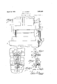
- Fig. 1 is a front elevational view of partof the press illustrating the guard in extended 25 position.
- Fig. 2 is a side view of the same.
- Fig. 3 is a front view showing part of the press and illustrating the guard in collapsed position.
- Fig. 4k is a detail section taken on line 44 of Fig. 2.
- Fig. 5 is a detail section taken on line 5-5 of Fig. 4.
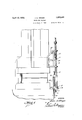
- Fig. 6 is a front view showing the modified orm.
- Fig. 7 is a side view of the mechanism of the modified form.
- a bed plate of a press is illustrated at 1, and a ram shows at 2. It will be understood thatthe plate punches or the like, and that the ram moves vertically in guides 3.
- a bracket 5 which carries an arm 6 which may be secured to the bracket by means of a bolt and an elongated slot 7 for adjustment purposes. 7
- the sweeping device of the guard consists of a lazy-tong construction with a pair of the more centrally disposed levers of the lazy-tongs pivotally connected, as'at 13, to the block 8, and with a second pair of the more centrally disposed levers pivotally connected, as at 1 1, to block 12.
- Each end of the lazy-tong construction is preferably provided with a roller 15 whichruns ina track 16. This track may also be'sups ported by the block 12.
- Each end of'the lazy-tong construction is also provided with i a device for engaging the' arm of the operator, as" shown at 17.
- a link 18 isinterposed between the engaging de vice1'17 and one of the levers'of thelazytong construction alink 18 for accommodating variation in the height of the adjacent lever in the-operation of the lazy-tong.
- the operator of the press works immediately in front of thecollapsed lazy-tongs with one armon each-side.
- the block 8 slides down upon the rod thus extending the lazytongsconstructioncausing the arm engaging devices 17 to .move outwardly in opposite directions from the central position to the positionshown in Fig. 1.-
- fl This is-especially movement of the arm sweeping devices of this guard is much less, and the movement accordingly can be slower so that the arms of the operator are more or less pushed out of the.
- the device can be easily applied and adjusted to presses of various sizes.
- the rod 9 is adjustable in its socket 11 so as to position the track just at the right height for'the bed-plate, or die on the bed plate, and also the arm 6 is adjustable on the bracket ,5 in order that the movements of the ram and guard devices can be properly coordinated.
- the sweeping device proper remains the same, consisting of the lazy-tong construction, but the operating means associated with the ram varies.
- a guard for a punch press or the like comprising a post fixed to the bed plate, a spring surrounding the post, a'sliding block onthe post above the-spring, means fixed relative to the bed plate for supporting the said plunger-carrying means and plunger, said plunger engaging the block upon downward movement of the ram to compress the first mentioned spring and. extend the lazy tong construction.
- a guard for a punch press or the like comprising a lazy tong construction, means connecting the lazy tong' construction to the bed plate, a vertically reciprocable element connected with the lazy tong construction, spring abutment means fixed with relation to the bed plate, a spring disposed between said element and said spring abutment means which is adapted to extend the lazy tong construction, a plunger, means on the ram for carrying the plunger, said plunger being arranged to engage the said vertically reciprocable element, a spring interposed between said means on the ram and the said plunger so that downward movement of the plunger is cushioned by said spring, whereby the lazy tong construction is both extended and contracted in aspring cushioned manner, said second named spring being stronger than the spring, a lazy-tone construction having sweep arms having a connection fixed with relation to' the bed plate and another connection with the sliding block, aplunger separate from a sliding bloc'k,-means on the ram c'arrying'the plunger, and a spring interposed between the
Landscapes
- Engineering & Computer Science (AREA)
- General Engineering & Computer Science (AREA)
- Mechanical Engineering (AREA)
- Press Drives And Press Lines (AREA)
Description
April 12, 1932. J. A. HINGER 1,853,425
GUARD FOR PRES SES Filed Sept. 7, 1928 4 Shee ts-Sheet l I I l l I l INVENTOR.
A TTORNE Y.
April 12, 1932. I j HlNGER 1,853,425
GUARD FOR PRESSES Fil ed Sept. 7, 1928 4 Sheets-Sheet 2 J r F. 3 m 5 I ENTOR. J57??? r? ffinyer ATTORNEY.
April 12, 1932. J. A. HINGER GUARD FOR PRESS ES Filed Sept. 7, 1928 4 Sheets-Sheet 3 m w w m 7o'7m :4 7621962" v A TTORNE Y.
April 12, 1932- J. A. HINGER v GUARD FOR PRESSES Filed Sept. 7, 1928 4 sheets sh eet. 4
INVENTOR.
BY M A TTORNE Y.
' and the ram are equipped with suitable dies,
' Patented Apr. 12, 1932 ED AT S TENT orrlca JOHN A. HINGER, or :EAST CLEVELAND, OHIO, ASSIGNOR Tasman; orons con.
PORATION, or DETROIT, MICHIGAN,
A CORPORATION OF I GUARD FOR PRESSES I Applicationfiled September 7,. 1928. Serial No. 304,459.
This invention relates to a guard for a press, and it has to do especially with a sweep guard designed to sweep the arms and hands of an operator of a punch press or 5 thelike out of theway of the press when the same is operating.
;It is the objectof the invention to provide an improved guard construction which will not materially interfere with-the operator 10 in working at the press {and which has a relatively slow sweeping motion-which will sweep the arms and hands of an operator out of the way of the press without striking the arms or hands of the operator a hard blow which would in itself incapacitate the operator. In this regard it might be mentioned that guards have been used which sweep from one side of the press to the other. H The present invention contemplates a guard which moves from the central position outwardly toward both sides of the press.
In the accompanying drawings:
Fig. 1 is a front elevational view of partof the press illustrating the guard in extended 25 position.
Fig. 2 is a side view of the same. Fig. 3 is a front view showing part of the press and illustrating the guard in collapsed position.
Fig. 4k is a detail section taken on line 44 of Fig. 2.
Fig. 5 is a detail section taken on line 5-5 of Fig. 4.
Fig. 6 is a front view showing the modified orm.
Fig. 7 is a side view of the mechanism of the modified form.
In the accompanying drawings a bed plate of a press is illustrated at 1, and a ram shows at 2. It will be understood thatthe plate punches or the like, and that the ram moves vertically in guides 3. There is afiixed to the ram a bracket 5 which carries an arm 6 which may be secured to the bracket by means of a bolt and an elongated slot 7 for adjustment purposes. 7
There is a block 8 on the lower end of. the arm 6 which is in turn slidably mounted on a column or upright rod 9. This rod 9 is held fixed to the bed plate by means of a socket member 10 and set screw 11. It will thus be noted that as the ram raisesor lowers the block 8 reciprocates on the rod9. f
' There is a block 12 which is held stationary as regards the bed plate and this block may be carried by the rod 9, as illustrated in Fig. '2. The sweeping device of the guard consists of a lazy-tong construction with a pair of the more centrally disposed levers of the lazy-tongs pivotally connected, as'at 13, to the block 8, and with a second pair of the more centrally disposed levers pivotally connected, as at 1 1, to block 12. "Each end of the lazy-tong construction is preferably provided with a roller 15 whichruns ina track 16. This track may also be'sups ported by the block 12. 1
' Each end of'the lazy-tong construction is also provided with i a device for engaging the' arm of the operator, as" shown at 17. There isinterposed between the engaging de vice1'17 and one of the levers'of thelazytong construction alink 18 for accommodating variation in the height of the adjacent lever in the-operation of the lazy-tong.
' When the-ram is raised to its uppermost position the block 8 slides upon the rod 9 thus increasing the distance between points 13 and-14 and collapsing the lazy-tongs until they assumethe" position shown in Fig. 3.
The operator of the press works immediately in front of thecollapsed lazy-tongs with one armon each-side. When the press isoper ated to bring the ram down,the block 8 slides down upon the rod thus extending the lazytongsconstructioncausing the arm engaging devices 17 to .move outwardly in opposite directions from the central position to the positionshown in Fig. 1.- In so doing, the device f17 engagethe arms of the operator,=if his arms are in the way, and pushes them out from underneath-the'ram. flThis is-especially movement of the arm sweeping devices of this guard is much less, and the movement accordingly can be slower so that the arms of the operator are more or less pushed out of the.
way instead of being' given a sudden blow. Moreover, the device can be easily applied and adjusted to presses of various sizes. For example, the rod 9 is adjustable in its socket 11 so as to position the track just at the right height for'the bed-plate, or die on the bed plate, and also the arm 6 is adjustable on the bracket ,5 in order that the movements of the ram and guard devices can be properly coordinated.- 3 i r v Inthe modified form the sweeping device proper remains the same, consisting of the lazy-tong construction, but the operating means associated with the ram varies. In thisform there is a bracket 20 secured to the ram, and the rod 9 is provided witha collar 21; fixed thereto as by means of a pin or the like 22, with a coil'spring 23 interposed between the upper arm of the bracket and the collar." There is also interposed between the block 8 and block 12 a coil spring 24.
, When the'ram comes down, the arm 20 is pushed, downwardly and the tendency is to compress spring 23. This moves the collar 8 down and spring 24-is compressed; the spring 23' is somewhat stronger than spring 24. Whenthe ram lifts, the spring 24 raises the collar 8 and rod 9; It will be understood, of course, that the tongs are extended and 'collapsed in this operation. Preferably, when the ram is in raised-position, that being the position shown in'Fig.'7, the spring 23 is in substantially its normal position.
. .Byvthis construction thereis a cushioning action when the arm sweeping devices; strike the arms of the operator, which comes about by reason ofthe fact that the ram pushes the arms of theoperator outwardly under the spring action of spring 23.- v y 1. A guard for a punch press or the like, comprising a post fixed to the bed plate, a spring surrounding the post, a'sliding block onthe post above the-spring, means fixed relative to the bed plate for supporting the said plunger-carrying means and plunger, said plunger engaging the block upon downward movement of the ram to compress the first mentioned spring and. extend the lazy tong construction.
2. A guard for a punch press or the like, comprising a lazy tong construction, means connecting the lazy tong' construction to the bed plate, a vertically reciprocable element connected with the lazy tong construction, spring abutment means fixed with relation to the bed plate, a spring disposed between said element and said spring abutment means which is adapted to extend the lazy tong construction, a plunger, means on the ram for carrying the plunger, said plunger being arranged to engage the said vertically reciprocable element, a spring interposed between said means on the ram and the said plunger so that downward movement of the plunger is cushioned by said spring, whereby the lazy tong construction is both extended and contracted in aspring cushioned manner, said second named spring being stronger than the spring, a lazy-tone construction having sweep arms having a connection fixed with relation to' the bed plate and another connection with the sliding block, aplunger separate from a sliding bloc'k,-means on the ram c'arrying'the plunger, and a spring interposed between the
Priority Applications (1)
| Application Number | Priority Date | Filing Date | Title |
|---|---|---|---|
| US304459A US1853425A (en) | 1928-09-07 | 1928-09-07 | Guard for presses |
Applications Claiming Priority (1)
| Application Number | Priority Date | Filing Date | Title |
|---|---|---|---|
| US304459A US1853425A (en) | 1928-09-07 | 1928-09-07 | Guard for presses |
Publications (1)
| Publication Number | Publication Date |
|---|---|
| US1853425A true US1853425A (en) | 1932-04-12 |
Family
ID=23176607
Family Applications (1)
| Application Number | Title | Priority Date | Filing Date |
|---|---|---|---|
| US304459A Expired - Lifetime US1853425A (en) | 1928-09-07 | 1928-09-07 | Guard for presses |
Country Status (1)
| Country | Link |
|---|---|
| US (1) | US1853425A (en) |
Cited By (2)
| Publication number | Priority date | Publication date | Assignee | Title |
|---|---|---|---|---|
| US2443726A (en) * | 1946-01-19 | 1948-06-22 | Hubert E Dickerman | Safety guard for presses and the like |
| US3780595A (en) * | 1972-08-07 | 1973-12-25 | Bendix Corp | Linear motion mechanism and motion amplifying device therefor |
-
1928
- 1928-09-07 US US304459A patent/US1853425A/en not_active Expired - Lifetime
Cited By (2)
| Publication number | Priority date | Publication date | Assignee | Title |
|---|---|---|---|---|
| US2443726A (en) * | 1946-01-19 | 1948-06-22 | Hubert E Dickerman | Safety guard for presses and the like |
| US3780595A (en) * | 1972-08-07 | 1973-12-25 | Bendix Corp | Linear motion mechanism and motion amplifying device therefor |
Similar Documents
| Publication | Publication Date | Title |
|---|---|---|
| US2657009A (en) | Jack | |
| US1853425A (en) | Guard for presses | |
| US2761406A (en) | Die for drawing sheet material | |
| US2510341A (en) | Glove turning apparatus | |
| US1354785A (en) | Die-cushion | |
| US2480378A (en) | Reciprocating bender for forming tubular bushings | |
| US2536643A (en) | Reciprocating dies with pivoted and slidable end shaping dies | |
| US1629538A (en) | Pressure-pad-control device | |
| US2354291A (en) | Press | |
| US2273454A (en) | Underfeed riveting machine | |
| US3427853A (en) | Apparatus to avoid bending during forging | |
| US984851A (en) | Forging-machine. | |
| US1636110A (en) | Pressure cushion | |
| US1931488A (en) | Cotton tramper feed mechanism | |
| US1872242A (en) | Press | |
| US4137795A (en) | Safety guard for power presses | |
| US2171523A (en) | Safety guard for power presses | |
| US1350568A (en) | Machine for pressing rings having profiled inner surfaces | |
| US2939349A (en) | Press and feed mechanism for making anode balls | |
| US2392925A (en) | Apparatus for working metal | |
| US1482263A (en) | Glass-pressing mechanism | |
| US2501347A (en) | Double sweep safety guard for power presses | |
| US1749428A (en) | Method and means for forming hollow articles | |
| SU1461580A1 (en) | Die set for die forging | |
| US2139551A (en) | Extrusion press |