US1853400A - Anchor - Google Patents
Anchor Download PDFInfo
- Publication number
- US1853400A US1853400A US463793A US46379330A US1853400A US 1853400 A US1853400 A US 1853400A US 463793 A US463793 A US 463793A US 46379330 A US46379330 A US 46379330A US 1853400 A US1853400 A US 1853400A
- Authority
- US
- United States
- Prior art keywords
- anchor
- plate
- rod
- earth
- hole
- Prior art date
- Legal status (The legal status is an assumption and is not a legal conclusion. Google has not performed a legal analysis and makes no representation as to the accuracy of the status listed.)
- Expired - Lifetime
Links
- 241001449342 Chlorocrambe hastata Species 0.000 description 11
- 238000004873 anchoring Methods 0.000 description 6
- 238000003780 insertion Methods 0.000 description 5
- 230000037431 insertion Effects 0.000 description 5
- 230000008878 coupling Effects 0.000 description 3
- 238000010168 coupling process Methods 0.000 description 3
- 238000005859 coupling reaction Methods 0.000 description 3
- 230000001788 irregular Effects 0.000 description 3
- 238000000034 method Methods 0.000 description 3
- 230000000630 rising effect Effects 0.000 description 2
- 229910052729 chemical element Inorganic materials 0.000 description 1
- 238000006073 displacement reaction Methods 0.000 description 1
- 238000005553 drilling Methods 0.000 description 1
- 238000000605 extraction Methods 0.000 description 1
- 238000009877 rendering Methods 0.000 description 1
Images
Classifications
-
- E—FIXED CONSTRUCTIONS
- E02—HYDRAULIC ENGINEERING; FOUNDATIONS; SOIL SHIFTING
- E02D—FOUNDATIONS; EXCAVATIONS; EMBANKMENTS; UNDERGROUND OR UNDERWATER STRUCTURES
- E02D5/00—Bulkheads, piles, or other structural elements specially adapted to foundation engineering
- E02D5/74—Means for anchoring structural elements or bulkheads
- E02D5/80—Ground anchors
Definitions
- This invention relates to devices adapted to be imbedded in the earth for anchorage purposes and is particularly directed to an anchor adaptable for use in firmly securing 0 ground and the guy wire thereupon becomes or anchoring guy wires to the ground.
- This objective is primarily accomplished by the particular contour ofthe upper surface of the anchor which disposes an upper concave'surface in engagement with the earth above it in such 'manner that it would be necessary to break loose or displace all the ground above the anchor before the anchor will be dislocated.
- a hole is drilled into the earth obliquely relative to the surface thereof and undermining or extend ing under the spot at which the guy wire is to be anchored, and an anchor post or rod is driven downwardly from the point of guy wire attachment entering the hole at right angles or transversely thereto, whereupon the anchor is lowered into position upon the lower end of the rod and against the lower side of the hole.
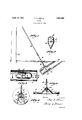
- Figure 1 is ageneral view illustrating a cross section of the earth adjacent a pole and showing a guy wire anchored by the device and by means of the method of thepresent invention.
- Figure 2 is a top plan view of the anchor.
- Figure 3 is a sectional view taken on line 3-'3, Figure 2, illustrating the anchor in longitudinal section and showing the anchor rod position.
- FIG. '4 s a sectional'view taken on line 44', Figure 3, illustrating the semicircular the anchor or'ground plate 11.
- These ele-- ments are inserted or placed within the earth separately and are coupled in set position.
- the environment necessary is an element to a be braced such as a post 12, a guy wire 13 extending down from the post and a cavity V drilled into the earth by means of an auger obliquely to'the earth surface and towardthe
- the anchor 11 consists of a formed plate which is generally straight in longitudinal section and arcuate in cross section.-
- Anv irregular pyramid or hollow cone 15 is formed upwardly 'intermediatelyf of the length of the plate. "This cone or pyramid is slightlyflattened in cross section so as to permit greaterexposed concave area on the upper surface of the plate
- the anchor I may [cone or laterally displaced.
- the central r'aisedportion or irregular pyramid includes a slot 16 in a portion of the lwall thereof which may be described as the end portion or longitudinally disposed side relative to the plate. 7
- the slot 16 extends substantially from the straight longitudinal extent of the plate to the apex of the cone.
- the slot is of a, substantial width'from the bottom ofv the pyramid a considerable distance upwardly.
- Toward the top of the pyramidthe width of the slot is reduced as at 17. This slot permits the plate to be inserted over the headed end of.
- the lower portion of the slot being of a suitable width for permittingconvenient entrance of the head to the interior of the hollow cone and the remainder of the slotvbein'g of a width suitable for permitting travel of the platedownwardlyabout the rod against the head, whereby the head cannot beextracted axially throughthe apex of the Toward what I may betermed the upper end of the plate, an
- ing device of some sort for a the anchor into and manipulating the same into its position aperture 18 is provided permitting attachment of the anchor to the hook of an insertinitially lowering position within the cavity upon the head ofthe rod.
- the rod 10 provides an eye 19 at one end and is screw-threaded on the opposite end. Upon initial insertion into the earth, the rod is free of attachment to the guy wire.- For facilitating insertion of therod into the earth,
- a spearhead 20 is provided. This spear head and stopping interiorly of the pointed tip.
- a bore Ql is provided in the spear head extending axially thereof from the rounded end inwardly o U
- a square cross passage 22 is provided intermediate of the length of the head transversely intersecting the aforesaid bore. This passage is of slightly greater width than the distance between opposing faces of the nut 28. The'nut is slid into position from the side of the head and aligned with the central bore, being held against rotation by the engagement of its opposite sides with the sides of the passage and the rod is then easily screwed into adjusted position in the nut.
- the rod With the spear head in position on the lower end of the rod, the rod is driven into the earth in alignment with the proposed taut extent of the guy wire and at right angles to theauger hole until the headed end of the rod breaks into the auger hole.
- the anchor is. then slid along the lower side of the oblique hol-e, its curvature approximately fitting the curvature of the hole, the anchor being low- 9 ered'by'means of a hooked tool attached to theaperture at its upper end.
- the anchor is slid over/the head through the wide portion-of the slot andthe anchor rodthen assumes a position in axial align- .9 ment with the cone of the anchor. There upon the rod is drawn upwardlyuntil the rounded end of the'head engages in the correspondingly rounded inner surface of the apex of t the hollow cone. Thereupon' the auger hole is entirely filled with the previously removed earth and the. earth is firmly tamped in position.
- an anchor plate having a concave upper surface and a hollow pyramid centrally thereof, said pyramid including a slot in the side wall thereof of narrow width toward the apex, and a rod having a head on its lower end adapted to be inserted into the pyramid through the slot.
- a device for anchoring guy wires consisting of a plate having a straight longitudinal extent and arcuate cross section and including a central portion extended from the concave side of the plate provided with means for attachment to the part to be anchored, the concave side being adjacent to the guy wire.
- An anchor comprising, a plate, arcuate in cross section and generally straight longitudinally, a raised portion formed centrally and at the concave side thereof, said raised portion having a lateral orifice formed therein, and meansinsertable into the apex of the raised portion through the orifice for attaching an element to be anchored'thereto, said element being on the concave side of the plate.
- a method of anchoring guy wires consisting of drilling a hole obliquely into the earth and toward the object to be braced by the guy wire, driving a rod into the earth in alignment with the guy wire to be attached thereto at right angles to the hole for extending the inner end of the rod into the hole, lowering a plate into the hole into engagement with the inner end of the rod against the lower side of the hole, and re placing the earth within the hole above the plate and against the upper surface of said plate.
- a plate having a concave upper surface, a hollow irregular cone rising centrally of saidplate and having a rounded inner surface at the apex thereof, a rod, said rod having a spear head adjustably mounted on one end, said spear head having a rounded inner end adapted to engage the rounded inner side of the apex of the hollow cone, and said cone laterally slotted to permit lateral insertion of the spear head and rod within the cone.
- a plate having its upper surface concave in cross section and, generally straight in longitudinal section, including a hollow pyramid rising centrally of the plate, a rod, a spear head for said rod,
Landscapes
- Engineering & Computer Science (AREA)
- Structural Engineering (AREA)
- Life Sciences & Earth Sciences (AREA)
- General Life Sciences & Earth Sciences (AREA)
- Mining & Mineral Resources (AREA)
- Paleontology (AREA)
- Civil Engineering (AREA)
- General Engineering & Computer Science (AREA)
- Piles And Underground Anchors (AREA)
Description
F. N. BIERCE April 12, 1932.
ANCHOR Filed June 25, 1930 4/ w W l INVENTOR ATTORNEYS Patented Apr. 12, 1932 Warren srArss FRED N. BIERGE, CINCINNATI, OHIO.
ANCHOR Application filed June 25,
This invention relates to devices adapted to be imbedded in the earth for anchorage purposes and is particularly directed to an anchor adaptable for use in firmly securing 0 ground and the guy wire thereupon becomes or anchoring guy wires to the ground.
The chief ditficulty encountered in the application of anchoring devices for guy wires or the like is that the anchor after the passage of time tends to loosen within the slack. Various devices have been developed for causing the anchor to positively and definitely remain in the original position without shifting due to the constant heavy pull or strains on the guy wire tending to extract the anchor fro-m the ground.
It is therefore an object of this invention to provide an improved anchor or ground plate for guy wires or the like which has an o extremely effective contour rendering the anchor incapable of dislocation due to strains on the guy wire. This objective is primarily accomplished by the particular contour ofthe upper surface of the anchor which disposes an upper concave'surface in engagement with the earth above it in such 'manner that it would be necessary to break loose or displace all the ground above the anchor before the anchor will be dislocated.
I It is another object of the present invention to provide a new method of inserting or planting an anchor in firmly anchored position without disturbing the major portion of the ground above it. For this purpose a hole is drilled into the earth obliquely relative to the surface thereof and undermining or extend ing under the spot at which the guy wire is to be anchored, and an anchor post or rod is driven downwardly from the point of guy wire attachment entering the hole at right angles or transversely thereto, whereupon the anchor is lowered into position upon the lower end of the rod and against the lower side of the hole.
anchor.
In view of the foregoing, it is another object of this invention to provide a new and The hole is then refilled and the dirt is tamped into position over the p 1930. Serial No. 463,793.
ing to the radius of the hole, which anchor is 7 adapted to lie against the lower side of the hole to permit the replacement of the earth over the anchor thus placed. T The anchor is located in this manner so as to permit a com plete' refilling of the upper side of the cavity at the point of entry of the rod for the reason that this side of the. aperture is generally caved in by the entrance of the driven rod.
It is another object of this invention to provide a novel device for permitting ready insertion of the rodand foreifecting a speedy and convenient couple between :the anchor and the rod within the ground which couple. is incapable of loosening after the earth has been replaced and the guy wire stretched. v
It is still another object of this invention to provide a guy wire anchorage means wherein the anchor plate disposed withinthe ground and the guy wire connectlng rod are flexibly coupled at a pointoutward or forward'of the general plate surface for delivering the pulling strain exerted through the rod to a coupling point in an advanced position relative to the plate, and to further .pro-
vide that the'central shape of the plate at the point of coupling is such that the tensional stresses on the plate are extended toward the. margins thereof ratherthan to the center 'By this arrangement, it is provided that there is less opportunity for collapsing of the central portion of the plate and due to the particular transverse curvature of the plate in combination with this coupling means an unusual sturdy anchor plate is provided.
Other objects and certain advantages will I be more fully apparent from a description of the accompanyingdrawings, in which: I
Figure 1 is ageneral view illustrating a cross section of the earth adjacent a pole and showing a guy wire anchored by the device and by means of the method of thepresent invention.
Figure 2 is a top plan view of the anchor. Figure 3 is a sectional view taken on line 3-'3,Figure 2, illustrating the anchor in longitudinal section and showing the anchor rod position.
Figure '4; s a sectional'view taken on line 44', Figure 3, illustrating the semicircular the anchor or'ground plate 11. These ele-- ments are inserted or placed within the earth separately and are coupled in set position. The environment necessary is an element to a be braced such as a post 12, a guy wire 13 extending down from the post and a cavity V drilled into the earth by means of an auger obliquely to'the earth surface and towardthe Referring specifically to the drawings, the details of the mentioned elements are as follows. The anchor 11 consists of a formed plate which is generally straight in longitudinal section and arcuate in cross section.-
Anv irregular pyramid or hollow cone 15 is formed upwardly 'intermediatelyf of the length of the plate. "This cone or pyramid is slightlyflattened in cross section so as to permit greaterexposed concave area on the upper surface of the plate The anchor I may [cone or laterally displaced.
be ofrelatively light plate material provided itsv strength is sutficient to prevent deforma- The central r'aisedportion or irregular pyramid includes a slot 16 in a portion of the lwall thereof which may be described as the end portion or longitudinally disposed side relative to the plate. 7 The slot 16 extends substantially from the straight longitudinal extent of the plate to the apex of the cone. The slotis of a, substantial width'from the bottom ofv the pyramid a considerable distance upwardly. Toward the top of the pyramidthe width of the slot is reduced as at 17. This slot permits the plate to be inserted over the headed end of. the rod to which the guy wire is connected, the lower portion of the slot being of a suitable width for permittingconvenient entrance of the head to the interior of the hollow cone and the remainder of the slotvbein'g of a width suitable for permitting travel of the platedownwardlyabout the rod against the head, whereby the head cannot beextracted axially throughthe apex of the Toward what I may betermed the upper end of the plate, an
ing device of some sort for a the anchor into and manipulating the same into its position aperture 18 is provided permitting attachment of the anchor to the hook of an insertinitially lowering position within the cavity upon the head ofthe rod.
p The rod 10 provides an eye 19 at one end and is screw-threaded on the opposite end. Upon initial insertion into the earth, the rod is free of attachment to the guy wire.- For facilitating insertion of therod into the earth,
a spearhead 20 is provided. This spear head and stopping interiorly of the pointed tip.
includes a sharp point and a rounded opposite or upwardly disposed end. A bore Ql is provided in the spear head extending axially thereof from the rounded end inwardly o U A square cross passage 22 is provided intermediate of the length of the head transversely intersecting the aforesaid bore. This passage is of slightly greater width than the distance between opposing faces of the nut 28. The'nut is slid into position from the side of the head and aligned with the central bore, being held against rotation by the engagement of its opposite sides with the sides of the passage and the rod is then easily screwed into adjusted position in the nut.
With the spear head in position on the lower end of the rod, the rod is driven into the earth in alignment with the proposed taut extent of the guy wire and at right angles to theauger hole until the headed end of the rod breaks into the auger hole. The anchor is. then slid along the lower side of the oblique hol-e, its curvature approximately fitting the curvature of the hole, the anchor being low- 9 ered'by'means of a hooked tool attached to theaperture at its upper end.
The anchor is slid over/the head through the wide portion-of the slot andthe anchor rodthen assumes a position in axial align- .9 ment with the cone of the anchor. There upon the rod is drawn upwardlyuntil the rounded end of the'head engages in the correspondingly rounded inner surface of the apex of t the hollow cone. Thereupon' the auger hole is entirely filled with the previously removed earth and the. earth is firmly tamped in position.
vByplacing the anchor against the lower side of the auger hole, it is possible to tamp the dirt back into place to fill up the cavity caused byentry of the spear head into the auger hole. It will be apparent that an extremely small auger hole is sufiicient for placing the anchor. Therefore, there is e"- considerable amount of undisturbed earth between the lowermost depth of the cavity and the surface of the earth at the point of attachment to the guy wire, which undisturbed earth is incapable of displacement by 3115 normal strains on the guy wire.
For the anchor to become loosened or to be extracted from theearth, it is necessary that a block of earth, the cubical contents of which are determined by the width of the anchor and the distance of the anchor to the surface of the earth, be bodily removed or torn up. The anchor, due to its peculiar curvature, is incapable of providing any wedging action for easing extraction of the anchor. With ihe inner end of the spear head being rounded and engaging with the rounded inner side of the apex of the anchor. p1ate,'a rocking or flexible connection is provided. This cennection within the apex is Well in advance of the general plate surface and the walls of the hollow cone extending outwardly toward the edge margin of the plate deliver the tension more uniformly throughout the plate.
Having described by invention, I claim:
1. In a device of the class described, an anchor plate having a concave upper surface and a hollow pyramid centrally thereof, said pyramid including a slot in the side wall thereof of narrow width toward the apex, and a rod having a head on its lower end adapted to be inserted into the pyramid through the slot.
2. A device for anchoring guy wires consisting of a plate having a straight longitudinal extent and arcuate cross section and including a central portion extended from the concave side of the plate provided with means for attachment to the part to be anchored, the concave side being adjacent to the guy wire.
3. An anchor, comprising, a plate, arcuate in cross section and generally straight longitudinally, a raised portion formed centrally and at the concave side thereof, said raised portion having a lateral orifice formed therein, and meansinsertable into the apex of the raised portion through the orifice for attaching an element to be anchored'thereto, said element being on the concave side of the plate.
4. A method of anchoring guy wires consisting of drilling a hole obliquely into the earth and toward the object to be braced by the guy wire, driving a rod into the earth in alignment with the guy wire to be attached thereto at right angles to the hole for extending the inner end of the rod into the hole, lowering a plate into the hole into engagement with the inner end of the rod against the lower side of the hole, and re placing the earth within the hole above the plate and against the upper surface of said plate.
5. In an anchoring device, a plate having a concave upper surface, a hollow irregular cone rising centrally of saidplate and having a rounded inner surface at the apex thereof, a rod, said rod having a spear head adjustably mounted on one end, said spear head having a rounded inner end adapted to engage the rounded inner side of the apex of the hollow cone, and said cone laterally slotted to permit lateral insertion of the spear head and rod within the cone.
6. In an anchoring device, a plate having its upper surface concave in cross section and, generally straight in longitudinal section, including a hollow pyramid rising centrally of the plate, a rod, a spear head for said rod,
pyramid, and said pyramid laterally slotted to permit lateral insertion of the spear head and rod into the pyramid.
In witness whereof I hereunto subscribe my name.-
FRED N, BIERCE.
Priority Applications (1)
| Application Number | Priority Date | Filing Date | Title |
|---|---|---|---|
| US463793A US1853400A (en) | 1930-06-25 | 1930-06-25 | Anchor |
Applications Claiming Priority (1)
| Application Number | Priority Date | Filing Date | Title |
|---|---|---|---|
| US463793A US1853400A (en) | 1930-06-25 | 1930-06-25 | Anchor |
Publications (1)
| Publication Number | Publication Date |
|---|---|
| US1853400A true US1853400A (en) | 1932-04-12 |
Family
ID=23841391
Family Applications (1)
| Application Number | Title | Priority Date | Filing Date |
|---|---|---|---|
| US463793A Expired - Lifetime US1853400A (en) | 1930-06-25 | 1930-06-25 | Anchor |
Country Status (1)
| Country | Link |
|---|---|
| US (1) | US1853400A (en) |
Cited By (2)
| Publication number | Priority date | Publication date | Assignee | Title |
|---|---|---|---|---|
| US5775848A (en) * | 1996-09-30 | 1998-07-07 | Hubbell Incorporated | Earth and rock anchoring devices |
| US20250250813A1 (en) * | 2024-02-01 | 2025-08-07 | VAF Industries, LLC | Anchor system for supporting utility structure |
-
1930
- 1930-06-25 US US463793A patent/US1853400A/en not_active Expired - Lifetime
Cited By (2)
| Publication number | Priority date | Publication date | Assignee | Title |
|---|---|---|---|---|
| US5775848A (en) * | 1996-09-30 | 1998-07-07 | Hubbell Incorporated | Earth and rock anchoring devices |
| US20250250813A1 (en) * | 2024-02-01 | 2025-08-07 | VAF Industries, LLC | Anchor system for supporting utility structure |
Similar Documents
| Publication | Publication Date | Title |
|---|---|---|
| US5322386A (en) | Ground anchor device | |
| EA011700B1 (en) | An anchoring device | |
| US4096673A (en) | Method of anchoring | |
| US3350822A (en) | Steel reinforcer for wooden poles | |
| US4727693A (en) | Apparatus for anchoring a traction member in the ground | |
| US5010698A (en) | Anchoring post assembly | |
| US2084239A (en) | Stake | |
| US1853400A (en) | Anchor | |
| US1791368A (en) | Anchor post | |
| US4761098A (en) | Drilling means serving as ground anchor and method | |
| US1726371A (en) | Pole reenforcement | |
| US2892518A (en) | Ground anchor | |
| US904198A (en) | Drive-anchor. | |
| US5050355A (en) | Ground anchor | |
| US855298A (en) | Earth-anchor. | |
| US1178282A (en) | Ground-anchor. | |
| US3570258A (en) | Method and apparatus for vibrating concrete columns | |
| US1775317A (en) | Land anchor | |
| PL233707B1 (en) | Ground anchor and method for setting anchors in the ground | |
| US853840A (en) | Grubber. | |
| US1317073A (en) | carlson | |
| US1869744A (en) | Fence post anchor | |
| US997852A (en) | Anchor for wire fences. | |
| US2044053A (en) | Dirt set corner post | |
| US837992A (en) | Fence-anchor. |