US18533A - Machine for folding paper - Google Patents
Machine for folding paper Download PDFInfo
- Publication number
- US18533A US18533A US18533DA US18533A US 18533 A US18533 A US 18533A US 18533D A US18533D A US 18533DA US 18533 A US18533 A US 18533A
- Authority
- US
- United States
- Prior art keywords
- sheet
- rollers
- lever
- bar
- machine
- Prior art date
- Legal status (The legal status is an assumption and is not a legal conclusion. Google has not performed a legal analysis and makes no representation as to the accuracy of the status listed.)
- Expired - Lifetime
Links
- 238000000034 method Methods 0.000 description 6
- 230000000994 depressogenic effect Effects 0.000 description 4
- 241001473780 Sideroxylon lanuginosum Species 0.000 description 3
- 238000005520 cutting process Methods 0.000 description 3
- 210000003128 head Anatomy 0.000 description 3
- 230000000284 resting effect Effects 0.000 description 3
- 238000007599 discharging Methods 0.000 description 2
- 238000007373 indentation Methods 0.000 description 2
- 230000000717 retained effect Effects 0.000 description 2
- 239000011230 binding agent Substances 0.000 description 1
- 238000010276 construction Methods 0.000 description 1
- 230000002950 deficient Effects 0.000 description 1
- 230000000881 depressing effect Effects 0.000 description 1
- 239000002184 metal Substances 0.000 description 1
- 229910052751 metal Inorganic materials 0.000 description 1
- 238000012856 packing Methods 0.000 description 1
- 239000000126 substance Substances 0.000 description 1
Images


Classifications
-
- B—PERFORMING OPERATIONS; TRANSPORTING
- B65—CONVEYING; PACKING; STORING; HANDLING THIN OR FILAMENTARY MATERIAL
- B65H—HANDLING THIN OR FILAMENTARY MATERIAL, e.g. SHEETS, WEBS, CABLES
- B65H45/00—Folding thin material
- B65H45/12—Folding articles or webs with application of pressure to define or form crease lines
Definitions
- My invention relates to improvements in the paper folding machine for which a patent was granted to me on the seventh day of October, in the year of Aour Lord one thousand eight hundred and fifty six and these improvements consist, first, in forcing the edges of the printed sheet between the folding rollers in advance of the middle of said sheet; second, in temporarily arresting the motion of the first pair of folding rollers; third, in the peculiar location and method of operating the register pins, and the method of extracting the same from the sheet; fourth, in preventing the paper during its passage through the machine from rebounding; fifth, dividing the printed sheet into two halves by cutting from the folded edge a strip, and discharging the said strip from the machine; sixth, retaining one half of the divided sheet while the other half is being folded, so that the two halfs can be folded successively; seventh, a manner of packing and retaining the folded sheets so that the folded heads and backs shall coincide with each other, also a method of separating the imperfect from the perfect sheets, the devices for accomplishing which are fully set forth hereafter.
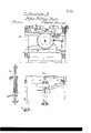
- Figure l is a ground plan of my improved paper folding machine; Fig. 2, a side elevation of the same with the front of the frame removed; Fig. 3, a transverse section on the line 1 2 (Fig. 2) Fig. 4L, a transverse section of the upper part of the machine on the line 3 4 (Fig. 2) Fig. 5, an enlarged sectional view of the register pins, showing the mode of operating the same; Fig. 6, a detached sectional view of the clutch for arresting the motion of the first pair of rollers; Fig. 7 is a sectional view of the pressure bars when elevated.
- the main framework of the machine consists of four uprights A, two upper longitudinal pieces B and B', two lower longitudinal pieces C and C two upper transverse bars D and D and two lower transverse bars E and E, and an intermediate transverse bar F the whole being firmly secured together.
- Gr is the main shaft of the machine caused by any convenient driving apparatus to turn in the hangers a and ZJ, the former being secured to the transverse bar D, and the latter to the bar F.
- a cam I-I arranged to actuate the lever I on the shaft J, the latter turning in suitable boxes on the opposite longitudinal pieces B and B.
- the long bent lever K, and short straight lever L are also secured.
- the lever K is bent at right angles as seen in the plan view Fig. l, and to the bent portion c is secured the metal blade M which when depressed coincides with the space between the two rollers N, and N, the latter turning in suitable boxes attached to the opposite longitudinal pieces B and B.
- One of these rollers is caused to revolve by the same driving apparatus which turns the shaft G.
- a series of endless tapes i pass around the roller, N under the roller N and through eyes or pulleys on the bracket f which is secured to the framework of the machine.
- a rod g To the end of the lever L is connected a rod g, near the end of which are two adjustable nuts h so arranged as to strike alternately against the pin of the lever when a reciprocating motion is imparted to the rod g by the vibration of the lever L, thus giving an intermittent vibrating motion to the lever O, as well as to the shaft P to which the lever is secured.
- the object of this intermittent motion will be apparent hereafter.
- the shaft P turns in brackets projecting from and secured to a bar Q, the ends of which fit and slide in dovetailed projections on the underside of the opposite longitudinal pieces B and B, one end of the bar being furnished with a bracket y' (see Fig. 3), through which passes the screw 73, the latter screwing into the frame (see Fig. 3), so that the bar may be adjusted at pleasure.
- a bracket y' see Fig. 3
- a bent plate Z the projecting end of which fits into grooves formed on one end of the rollers N and N, so that any movement of the bar is communicated to the said rollers.
- On the same bar Q are attached the plates m and to each of these a tube n (see Fig.
- This pin has two collars s and s, between which passes the end of the lever Z, which is secured to the shaft P, so that an intermittent reciprocating motion must be imparted to the register pins g.
- the tube p is also furnished with two collars 75 and t', the collar 15 being struck by the collar s and the collar t by the collar s on the register pin at certain intervals, as hereafter set forth, so that an intermittent reciprocating motion is also imparted to the tube p, the latter being retained during the time which elapses between the striking of the collars 25 and t by the spring u, one end of which is secured to the plate m, the other passing through a slot in the tube n and bearing against the side of the tube p.
- a cam R formed to actuate the lever S as the shaft revolves.
- This lever is secured to a shaft T which turns in suitable boXes attached to the longitudinal piece B.
- the arm U is secured to this shaft to the forked end of which is permanently attached a bar fw (see Fig. l).
- a bar fw see Fig. l.
- two plates a" are so secured by means of screws y, y, which pass through oblong holes, and screw into the bar, that said plates may slide hori- Zontally to a limited extent but have no other movement independent of the bar.
- a spring catch 4L is attached to a bar 5 on the frame of the machine or otherwise to a plate which covers the machine, and this catch is so formed and situated that the one or other of the pins on the face of the cam e shall come in contact with the hook as the lever U vibrates.
- V and V are the second pair of rollers, the space between which coincides with the rows of line points on the plates and when the lever U. is depressed.
- One of these rollers is driven by the cog-wheel W on the shaft G gearing into the pinion X on the end of the'roller.
- Above these rollers are the two pressure bars 6 and 7, furnished at each end with projecting spindles arranged to turn in suitable eyes attached to the permanent frame of the machine. The inner edges of these bars are beveled from the top, and when raised are nearly in contact with each other at a point perpendicular above that where the circumferences of the two rollers approach each other (Fig.
- a spiral spring 10 is attached at one end to a pin on one of these cogged segments, and at the other end to any convenient part of the frame.
- the position of the pin on the segment as regards that of the spiral spring is such that the latter may serve the purpose of retaining the pressure bars either in their elevated or depressed state, as seen in Fig. 7.
- a lever 11 On the back of the pressure bar 7, is secured a lever 11, the end of which is jointed to the rod 12, the end of the latter being slotted so as to slide on a pin on the end of the lever 13.
- the latter has its fulcrum on a pin attached to the transverse bar F of the frame, and is actuated by a cam 14 on the shaft G.
- One arm of the lever 13, is connected by means of the rod 15 to the end of the lever 16, which has its fulcrum on a pin 19, attached to one end of the adjustable bar 21 (which will be alluded to here after) directly opposite to the pin 19, and to the other end of they adjustable bar 21, is attached another pin 20, to which is hung a lever 17.
- These opposite levers 16 and 17, are connected together by the cross bar 18, a sectional view of which appears in Fig. 2.
- To the opposite longitudinal pieces B and B of the frame are secured the ends of the adjustable bar 21. Both the moving bar 18, and adjustable but stationary bar 21,
- a bracket 22 in which turns a spindle having on one end a suitable driving pulley and on the other end a disk wheel y having around its periphery a band of gum elastic or other suitable substance.
- This disk is so situated in respect to the shears, that when the bar 18 is raised the projecting portion of the knife underneath the latter comes in contact with the gum elastic band of the disk.
- Arms 24 project from and are secured to the bar 18, and on the ends of these arms are hung the rollers 23, corresponding in number to the endless tapes CZ, cZ, and so situated that when the bar 18 is depressed the rollers are in contact with the tapes and derive motion therefrom.
- 26 and 27 are the third pair of folding rollers, turning in boxes attached to the frame, and 28 and 29, Fig. 3, the fourth pair of folding rollers.
- a plate 30 Under the last pair of rollers and between the same is a plate 30, which has pins at each end turning in the frame of the machine, so that the plate may assume the position shown in Fig. 2, this movement of the plate being under the control of the operator as it is connected to a treadle by means of a rod 34, lever 33, and treadle shaft 32.
- an angular trough 35 for the reception of the folded sheets.
- a plunger 36 connected by means of a rod to the end of the lever 38, on the vertical shaft 39, which turns in the frame of the machine and to which is attached another lever 40, the end of which is connected by means of a rod to a pin on the cam R, the turning of which imparts a vibrating motion to the levers and consequently a reciprocating motion to the plunger in the trough.
- a plate 41 likewise fits and slides in the trough 35 andV is clamped to the same by means of a spring 42, so as to produce a slight friction.
- a catch 43 projects from the fralne of the machine over the edge of the trough for a purpose which will be apparent hereafter.
- a spiral spring 47 connects the lever 46, to the frame of the machine, and has a tendency to maintain the clutch in contact with the pulley when the lever is free from contact with the arm K.
- the arm o now, by the peculiar action and form of the cam, descends until the points attached to the plates x and are just in contact with the paper, the points relnaining in that position, holding the paper while the cutting takes place.
- This bar 18, continues to rise until this strip is brought in contact with the gum elastic periphery of the disk y, which is caused to revolve by any suitable appliances in such a manner as to discharge the strip and force it free from the machine.
- the pressure bars 6 and 7 were elevated, as seen in Fig. 7, the spiral spring 10 maintaining them in this position in the manner before described until they are lowered by the further descent of the arm V.
- the plunger 36 At the time the sheet is dropping into the trough the plunger 36 is at the termination of its backward movement. Vhen the folded sheet however has been deposited in the trough the plunger by the action 0f the lever 40, shaft 39 and lever 38 advances and pushes the folded sheet forward, pressing it against others which have previously been deposited in the trough until it has passed the catch 43,
- the blade M which forces the paper between the first pair of rollers is slightly concave on the edge, in order that the edges of the sheet may be forced between the rollers slightly in advance of the middle of the same.
- the object of this is on account of the sheets of paper being more exposed and liable to eX- pand at the sides than at the middle through dampness and consequently apt to become wrinkled in passing between the rollers of the machine. The fact of striking the edges first entirely obviates this difficulty.
- the first pair of rollers N and N should be caused to revolve for a short period as above described for the following reasons. Should the rollers have a continuous revolving motion they would be apt to seize the sheet at the point where the original crease had been made by folding the sheets when carried from place to place previous to being submitted to the machine, the rollers seizing the sheet at this point instead of the exact point desired. But by causing the rollers to stop while the blade descends the latter strikes the sheet at the required point, creases the same and carries the doubled edge between the rollers, when the latter recommence their revolutions and fold the sheet accurately in the manner above described.
- the object of the peculiar arrangement of register pins as illustrated in Fig. 5 is as follows: Vhen the machine is placed on the covers of the machine, so that the holes made by the printing press are penetrated by the points of the pins g, and the sheet resting on the top of the tube p, the blade M descends and when nearly in contact with the points of the pins the latter descend while the tube p remains stationary, thus effectually withdrawing the pins from the paper, which but for this tube they might have a tendency to drag down the paper prematurely toward the rollers. When the blade is nearly in contact with the top of the tubes however the latter with the pins descend so as to allow the blade in conjunction with the rollers to make the required fold. When this has been accomplished, and when the blade rises preparatory to the submitting of another sheet to the machine, the pins and tubes, as will be easily seen on reference to the drawing resume their former position.
Landscapes
- Folding Of Thin Sheet-Like Materials, Special Discharging Devices, And Others (AREA)
Description
UNITED sTATEs PATENT oEEioE.
OYRUS CHAMBERS, JR., OF PHILADELPHIA, PENNSYLVANIA.
MACHINE FOR FOLDING PAPER.
Specification of Letters Patent N o. 18,533, dated November 3f, 1857.
To all whom 'it may concern:
Be it known that I, CYRUS CHAMBERS, J r., of the city of Philadelphia and State of Pennsylvania, have invented certain new and useful Improvements in Paper-Folding Machines; and I do hereby declare the following to be a full, clear, and exact description of the same, reference being had to the accompanying drawing and to the letters of reference marked thereon.
My invention relates to improvements in the paper folding machine for which a patent was granted to me on the seventh day of October, in the year of Aour Lord one thousand eight hundred and fifty six and these improvements consist, first, in forcing the edges of the printed sheet between the folding rollers in advance of the middle of said sheet; second, in temporarily arresting the motion of the first pair of folding rollers; third, in the peculiar location and method of operating the register pins, and the method of extracting the same from the sheet; fourth, in preventing the paper during its passage through the machine from rebounding; fifth, dividing the printed sheet into two halves by cutting from the folded edge a strip, and discharging the said strip from the machine; sixth, retaining one half of the divided sheet while the other half is being folded, so that the two halfs can be folded successively; seventh, a manner of packing and retaining the folded sheets so that the folded heads and backs shall coincide with each other, also a method of separating the imperfect from the perfect sheets, the devices for accomplishing which are fully set forth hereafter.
In order to enable others skilled in the art to make and use my invention I will now proceed to describe its construction and operation.
On reference to the drawing which forms a part of this specification, Figure l is a ground plan of my improved paper folding machine; Fig. 2, a side elevation of the same with the front of the frame removed; Fig. 3, a transverse section on the line 1 2 (Fig. 2) Fig. 4L, a transverse section of the upper part of the machine on the line 3 4 (Fig. 2) Fig. 5, an enlarged sectional view of the register pins, showing the mode of operating the same; Fig. 6, a detached sectional view of the clutch for arresting the motion of the first pair of rollers; Fig. 7 is a sectional view of the pressure bars when elevated.
Similar letters refer to similar parts throughout the several views.
The main framework of the machine consists of four uprights A, two upper longitudinal pieces B and B', two lower longitudinal pieces C and C two upper transverse bars D and D and two lower transverse bars E and E, and an intermediate transverse bar F the whole being firmly secured together.
Gr is the main shaft of the machine caused by any convenient driving apparatus to turn in the hangers a and ZJ, the former being secured to the transverse bar D, and the latter to the bar F. On the shaft Gr is secured a cam I-I arranged to actuate the lever I on the shaft J, the latter turning in suitable boxes on the opposite longitudinal pieces B and B. On this shaft are also secured the long bent lever K, and short straight lever L, the latter being alluded to hereafter. The lever K is bent at right angles as seen in the plan view Fig. l, and to the bent portion c is secured the metal blade M which when depressed coincides with the space between the two rollers N, and N, the latter turning in suitable boxes attached to the opposite longitudinal pieces B and B. One of these rollers is caused to revolve by the same driving apparatus which turns the shaft G. A series of endless tapes i pass around the roller, N under the roller N and through eyes or pulleys on the bracket f which is secured to the framework of the machine.
To the end of the lever L is connected a rod g, near the end of which are two adjustable nuts h so arranged as to strike alternately against the pin of the lever when a reciprocating motion is imparted to the rod g by the vibration of the lever L, thus giving an intermittent vibrating motion to the lever O, as well as to the shaft P to which the lever is secured. The object of this intermittent motion will be apparent hereafter.
The shaft P turns in brackets projecting from and secured to a bar Q, the ends of which fit and slide in dovetailed projections on the underside of the opposite longitudinal pieces B and B, one end of the bar being furnished with a bracket y' (see Fig. 3), through which passes the screw 73, the latter screwing into the frame (see Fig. 3), so that the bar may be adjusted at pleasure. On this sliding bar Q and near one end of the same, is secured a bent plate Z, the projecting end of which fits into grooves formed on one end of the rollers N and N, so that any movement of the bar is communicated to the said rollers. On the same bar Q, are attached the plates m and to each of these a tube n (see Fig. 5) and in this tube n another tube 29 is arranged to slide, and within the latter slide the register pins g. This pin has two collars s and s, between which passes the end of the lever Z, which is secured to the shaft P, so that an intermittent reciprocating motion must be imparted to the register pins g. It will be observed that the tube p is also furnished with two collars 75 and t', the collar 15 being struck by the collar s and the collar t by the collar s on the register pin at certain intervals, as hereafter set forth, so that an intermittent reciprocating motion is also imparted to the tube p, the latter being retained during the time which elapses between the striking of the collars 25 and t by the spring u, one end of which is secured to the plate m, the other passing through a slot in the tube n and bearing against the side of the tube p.
It will be observed on reference to Fig. 2 that a spring o is secured to the underside of the adjustable bar Q, bearing against the pin of the lever O in such a manner as to temporarily retain it, and consequently the register pins in the position it has been moved to by the adjustable nuts h, L, on the rod g.
On the end of the shaft Gr is secured a cam R formed to actuate the lever S as the shaft revolves. This lever is secured to a shaft T which turns in suitable boXes attached to the longitudinal piece B. To this shaft is secured the arm U to the forked end of which is permanently attached a bar fw (see Fig. l). In front of this bar two plates a" are so secured by means of screws y, y, which pass through oblong holes, and screw into the bar, that said plates may slide hori- Zontally to a limited extent but have no other movement independent of the bar. To the plates m and are attached a number of needles or line points projecting a slight distance below the plates, the points of one plate projecting in an angular direction, outward, and the points of the other plate also projecting outward in a contrary direction. Between the two plates and to the middle of the bar is permanently secured the plate e with fine points on its lower edge, which project a slight distance below the points of the plates x and A small spindle is attached to and projects from the bar w of the lever U and on this spindle is hung the cam 2, on the edge of which are two indentations, and on the face four pins, the edge of the cam coinciding with and bearing against small pins on the sliding plates and fc', as seen in Fig. 2. These opposite plates are connected together by the spiral spring 3, which has a tendency to draw the plates toward each other.
A spring catch 4L is attached to a bar 5 on the frame of the machine or otherwise to a plate which covers the machine, and this catch is so formed and situated that the one or other of the pins on the face of the cam e shall come in contact with the hook as the lever U vibrates.
V and V are the second pair of rollers, the space between which coincides with the rows of line points on the plates and when the lever U. is depressed. One of these rollers is driven by the cog-wheel W on the shaft G gearing into the pinion X on the end of the'roller. Above these rollers are the two pressure bars 6 and 7, furnished at each end with projecting spindles arranged to turn in suitable eyes attached to the permanent frame of the machine. The inner edges of these bars are beveled from the top, and when raised are nearly in contact with each other at a point perpendicular above that where the circumferences of the two rollers approach each other (Fig. 7 To the spindles on one end of the pressure bars are secured the cogged segments 8 and 9 so gearing into each other that the movements of the two blades are simultaneous. A spiral spring 10, is attached at one end to a pin on one of these cogged segments, and at the other end to any convenient part of the frame. The position of the pin on the segment as regards that of the spiral spring is such that the latter may serve the purpose of retaining the pressure bars either in their elevated or depressed state, as seen in Fig. 7.
On the back of the pressure bar 7, is secured a lever 11, the end of which is jointed to the rod 12, the end of the latter being slotted so as to slide on a pin on the end of the lever 13. The latter has its fulcrum on a pin attached to the transverse bar F of the frame, and is actuated by a cam 14 on the shaft G. One arm of the lever 13, is connected by means of the rod 15 to the end of the lever 16, which has its fulcrum on a pin 19, attached to one end of the adjustable bar 21 (which will be alluded to here after) directly opposite to the pin 19, and to the other end of they adjustable bar 21, is attached another pin 20, to which is hung a lever 17. These opposite levers 16 and 17, are connected together by the cross bar 18, a sectional view of which appears in Fig. 2. To the opposite longitudinal pieces B and B of the frame are secured the ends of the adjustable bar 21. Both the moving bar 18, and adjustable but stationary bar 21,
are furnished underneath with lsteel plates having sharp knife edges, so arranged that when the bar 18, is raised its knife edge passes in immediate contact with that of the bar 21, thus forming a pair of shears.
To the bar 21 is secured a bracket 22, in which turns a spindle having on one end a suitable driving pulley and on the other end a disk wheel y having around its periphery a band of gum elastic or other suitable substance. This disk is so situated in respect to the shears, that when the bar 18 is raised the projecting portion of the knife underneath the latter comes in contact with the gum elastic band of the disk.
Arms 24 project from and are secured to the bar 18, and on the ends of these arms are hung the rollers 23, corresponding in number to the endless tapes CZ, cZ, and so situated that when the bar 18 is depressed the rollers are in contact with the tapes and derive motion therefrom.
26 and 27 are the third pair of folding rollers, turning in boxes attached to the frame, and 28 and 29, Fig. 3, the fourth pair of folding rollers. Under the last pair of rollers and between the same is a plate 30, which has pins at each end turning in the frame of the machine, so that the plate may assume the position shown in Fig. 2, this movement of the plate being under the control of the operator as it is connected to a treadle by means of a rod 34, lever 33, and treadle shaft 32.
Under the last pair of folding rollers, and at the end of the machine is an angular trough 35 for the reception of the folded sheets. In this trough fits a plunger 36, connected by means of a rod to the end of the lever 38, on the vertical shaft 39, which turns in the frame of the machine and to which is attached another lever 40, the end of which is connected by means of a rod to a pin on the cam R, the turning of which imparts a vibrating motion to the levers and consequently a reciprocating motion to the plunger in the trough. A plate 41, likewise fits and slides in the trough 35 andV is clamped to the same by means of a spring 42, so as to produce a slight friction. A catch 43 projects from the fralne of the machine over the edge of the trough for a purpose which will be apparent hereafter.
In reference to the first folding rollers N and N it will be observed that the spindle of the former projects on one end beyond the frame. To this projecting portion of the spindle are hung the driving pulleys 44, and clutch 45, the former being loose on the spindle and the latter so arranged that the spindle can slide laterally, but not turn independently of the clutch, which is retained in its position by a bracket from a longitudinal bar B (See Fig. It will be seen on reference to Fig. 6, that the clutch is of a conical form, adapted to fit the conical recess in the pulley.
46 is a lever hung to a pin attached to the frame and one end of this lever has two projections, one fitting into a groove of the pulley 44, and the other, which forms a spring, bears against the back of the clutch. The other arm of the lever 46 has at its end an inclined projection so situated as to be struck by the arm K as the llatter descends. A spiral spring 47, connects the lever 46, to the frame of the machine, and has a tendency to maintain the clutch in contact with the pulley when the lever is free from contact with the arm K.
Operation: The moving parts of the machine being in the position shown in the drawing, that is with the arm K and blade M as well as the register pins g elevated, the operator places a sheet of paper on the cover of the machine (which is shown in the drawing in red lines Fig. 2) in such a position that the register pins g shall fit into the register holes made in the sheet by the printing press. The arm K now by the action of the cam H on the shaft G descends, and when it has nearly arrived at its lowest position, strikes the inclined projection on one arm of the lever 46, moving the latter' so that the two projections on the opposite end act upon the pulley 44, and clutch 45 in the following manner: One of the projections slides the pulley outward and free from the clutch. The other and elastic projection bears against the back of the clutch, and acts as a brake for the same, thereby stopping the further revolution of the rollers N and N. Vhen the blade M has arrived close to but not in actual contact with the paper, the register pins by the movement of the lever r as actuated by the lever L, rod g and lever O suddenly descend, leaving the tube p stationary for a brief period, during which the sheet rests on top of that tube. Vhen the blade M has nearly touched the paper the tube p likewise suddenly descends by the striking of the collar s of the register pins against the collar t of the tube. The blade after the descent of the register pins continues its downward movement, creasing and forcing the paper between the rollers N and N', which are at present stationary. As soon as the blade has arrived at its lowest position however it suddenly rises, thereby relieving the lever 46, and consequently by the spring 47, causing the lever to force the pulley against the clutch and relieving the back of the latter from the pressure of the elastic projection, when the rollers resume their revolving motion, drawing the paper between them, so that it can be carried off by the tapes until its folded edge strikes the bar 18, said edge resting above the knife edge, which is secured to the underside of this bar. When the folded sheet of paper arrives at the position alluded to, it has a tendency to recoil. This is prevented by the arresting rollers 23, which are hung to the end of the arms 24 on the bar 18, the rollers being on the top of the sheet. The arm o now, by the peculiar action and form of the cam, descends until the points attached to the plates x and are just in contact with the paper, the points relnaining in that position, holding the paper while the cutting takes place. This is accomplished by the cam 1111 acting upon the lever 13, rod 15 and lever 16 and consequently upon the bar 18, which rises with the edge of the knife V in conjunction with the edge of the knife of the bar 21 cuts a narrow strip from the folded edge of the sheet, which is now consequently separated into two distinct and separate sheets, the strip remaining upon the ledge formed by the projection of the knife beyond the bar 18. This bar 18, continues to rise until this strip is brought in contact with the gum elastic periphery of the disk y, which is caused to revolve by any suitable appliances in such a manner as to discharge the strip and force it free from the machine. It should be understood that while the points of the plates and fa are in contact with the paper, and during the time the cutting operation was taking place, the pressure bars 6 and 7, were elevated, as seen in Fig. 7, the spiral spring 10 maintaining them in this position in the manner before described until they are lowered by the further descent of the arm V. When this takes place the plates a: and with their points press down the paper between the pressure bars and open the same, so as to admit the creased edge of the paper between the second pair of rollers V and V. Before the paper is in actual contact with the rollers it is necessary that one sheet should be separated from the other in order that they may be separately folded by the succession of rollers. This is accomplished as follows: When the plates .r and are about depressing the pressure plates 6 and 7, the spring catch 4, which as before remarked as connected to the stationary bar 5 or otherwise to the cover plate of the machine, is caught by one or other of the pins projecting from the cam 2 and as the latter descends with the arm V it is evident that the cam must partially turn. This causes the elevated portion of its periphery to bear against the pins on the plates m and x', thereby sliding the latter outward, and causing the angular fine points to penetrate the upper sheet and retain it, while the lower sheet is by the further descent of the plate brought in contact with the rollers, and with the assistance of a series of tapes similar to those described in reference to the first pair of rollers carried to a posi tion ready to be acted upon by a succession of vibrating blades, rollers, and tapes until it receives the required number of folds. Just when the rollers V and V had caught and commenced folding the lower sheet the plates m and m are slightly elevated with the upper sheet adhering to the angular points. In this position the plates with the upper'sheet remain until the first sheet has arrived at a position ready to receive its last fold, when the plates x and m descend and force the upper sheet between the rollers V and V. Before it is caught by the latter however it is necessary that the sheet should be released from the points on the blades. This is effected by another pin on the cam 2 coming in contact with the hook of the spring catch 4, which turns the cam until the indentations on its periphery coincide with the pins on the plates x and w, which consequently by the action of the connecting spiral spring 3 move toward each other, so that the angular pieces slide from the orifices they have made in the upper sheet, which being thus relieved receives a succession of folds similar in number and by the same means as the folds imparted to the under sheet. As the folded sheet is discharged from the last pair of rollers 28 and 29 it drops into the angular trough 35 with the folded back of the sheet resting on the inclined bottom of the trough and the folded head against the inclined side of the same. At the time the sheet is dropping into the trough the plunger 36 is at the termination of its backward movement. Vhen the folded sheet however has been deposited in the trough the plunger by the action 0f the lever 40, shaft 39 and lever 38 advances and pushes the folded sheet forward, pressing it against others which have previously been deposited in the trough until it has passed the catch 43,
which bends the corner of the sheet partlyover the bent portion of the catch, recovering itself as soon as it has passed the same, which thus prevents the folded sheet from returning. On the bottom of the trough is another projection which retains the opposite corner of the sheet in a similar manner. Should it be discovered during the passage of the sheet through the machine that the sheet is defective the treadle 31 is depressed, causing the shaft 32 to turn partially around, moving the lever 33, rod 34 and consequently the plate 30, which thus assumes such an angular position that the folded sheet dropping from the last pair of rollers instead of being deposited in the trough is guided clear of the same and drops on the ground.
It should be understood that the blade M which forces the paper between the first pair of rollers is slightly concave on the edge, in order that the edges of the sheet may be forced between the rollers slightly in advance of the middle of the same. The object of this is on account of the sheets of paper being more exposed and liable to eX- pand at the sides than at the middle through dampness and consequently apt to become wrinkled in passing between the rollers of the machine. The fact of striking the edges first entirely obviates this difficulty.
It is necessary that the first pair of rollers N and N should be caused to revolve for a short period as above described for the following reasons. Should the rollers have a continuous revolving motion they would be apt to seize the sheet at the point where the original crease had been made by folding the sheets when carried from place to place previous to being submitted to the machine, the rollers seizing the sheet at this point instead of the exact point desired. But by causing the rollers to stop while the blade descends the latter strikes the sheet at the required point, creases the same and carries the doubled edge between the rollers, when the latter recommence their revolutions and fold the sheet accurately in the manner above described.
The object of the peculiar arrangement of register pins as illustrated in Fig. 5 is as follows: Vhen the machine is placed on the covers of the machine, so that the holes made by the printing press are penetrated by the points of the pins g, and the sheet resting on the top of the tube p, the blade M descends and when nearly in contact with the points of the pins the latter descend while the tube p remains stationary, thus effectually withdrawing the pins from the paper, which but for this tube they might have a tendency to drag down the paper prematurely toward the rollers. When the blade is nearly in contact with the top of the tubes however the latter with the pins descend so as to allow the blade in conjunction with the rollers to make the required fold. When this has been accomplished, and when the blade rises preparatory to the submitting of another sheet to the machine, the pins and tubes, as will be easily seen on reference to the drawing resume their former position.
It should be understood that the machine above described is designed for folding sheets of paper printed on both sides from the same form; hence the necessity of dividing the sheet into two, retaining the upper half of the sheet until the lower half is folded, and subsequently folding the upper half-in other words folding the two halves of the sheet in succession, the method of accomplishing which has been fully described above.
The method of arresting the sheet preparatory to dividing and the means of disposing of the strip cut from the folded edge, also the means of separating the imperfect sheets from the perfect ones, will be easily understood without further reference.
As the folded sheets fall into the trough and are forced forward by the plunger against the plate 41, which recedes, sufficient friction is imparted to the latter by its spring above alluded to that the receding does not take place until a sufficient pressure has been imparted to the folded sheets to pack them comparatively tight together. Another advantage of the trough and plunger is that the packed sheets are in exactly the same relative position to each other, all the backs and heads of the same coinciding and on a uniform level, ready for being packed, stored or conveyed away preparatory to being placed in the hands of the binder.
I do not desire to confine myself to the precise form or method of operating the various moving parts of the machine, as
y they may be considerably modified without altering the result.
What I claim and desire to secure by Letters Patent is- 1. Forcing the edges of the sheet between the folding rollers in advance of the middle of the said sheet for the purpose specified.
2. Temporarily arresting the motion of the first pair of folding rollers in the manner substantially as herein described or any equivalent to the same.
3. The register pins g in combination with the tubes p when the same are arranged for joint operation substantially in the manner and for the purpose herein set forth.
4. The combination of the first pair of folding rollers N and N with the register pins g when the latter operate between the former in the manner herein described or any equivalent to the same.
5. Preventing the rebounding of the folded sheet during its passage through the machine previous tothe descent of any of the folding blades, by means of the arresting rollers herein described, the same operating in combination with the tapes substantially in the manner herein set forth.
6. Dividing the printed sheet into two halves by means of shears arranged, actuated and constructed substantially as herein set forth.
7. Discharging free from the machine the strip cut from the folded edge of the sheet by means of a revolving disk arranged and operating substantially in the manner herein set forth.
8. So constructing and arranging a machine for folding sheets of paper that the two halves of one sheet (said sheets having been printed on both sides from the same form) may be separated from each other and folded in succession.
12. The combination and arrangement by which the operations described are performed simultaneously or in succession to each other in the same machine.
In testimony whereof, I have signed my name to this specification before tWo subscribing Witnesses.
CYRUS CHAMBERS, JR.
Witnesses:
WILLIAM E. WALTON, WILLIAM DUT'ION.
Publications (1)
| Publication Number | Publication Date |
|---|---|
| US18533A true US18533A (en) | 1857-11-03 |
Family
ID=2081929
Family Applications (1)
| Application Number | Title | Priority Date | Filing Date |
|---|---|---|---|
| US18533D Expired - Lifetime US18533A (en) | Machine for folding paper |
Country Status (1)
| Country | Link |
|---|---|
| US (1) | US18533A (en) |
-
0
- US US18533D patent/US18533A/en not_active Expired - Lifetime
Similar Documents
| Publication | Publication Date | Title |
|---|---|---|
| US2285447A (en) | Means for applying reinforcements | |
| US4026199A (en) | Sheet end cutter and stripper | |
| US771852A (en) | Machine for opening and removing the contents of envelops. | |
| US18533A (en) | Machine for folding paper | |
| US1298586A (en) | Machine for making tubular box-shells. | |
| US1389197A (en) | Tray-making machine | |
| US2801578A (en) | Automatic machine for assembling cartons from blanks | |
| US1957957A (en) | Tray making machine | |
| US404517A (en) | Fruit-stoning machine | |
| US2244049A (en) | Veneer cutting machine | |
| US26090A (en) | Improvement | |
| US10166A (en) | William wheeler | |
| US228795A (en) | Pamphlet-trimmer | |
| US621965A (en) | Machine for scoring cardboard | |
| US170039A (en) | Improvement in paper-box machines | |
| US2681624A (en) | Candymaking machine | |
| US879544A (en) | Wrapping-machine. | |
| US2230169A (en) | Method of and means for manufacturing the flats of christmas crackers | |
| US847838A (en) | Machine for cutting web materials. | |
| US554839A (en) | Machine for binding edges with sheet metal | |
| US2074694A (en) | Machine for making match books | |
| US3144797A (en) | Slitter device tilting webs in accordance with the tilt of the receiving tray | |
| US24165A (en) | Machine for cutting soles | |
| US1027099A (en) | Paper cutting and collecting machine. | |
| US640249A (en) | Box-machine. |