US1853399A - Sign - Google Patents
Sign Download PDFInfo
- Publication number
- US1853399A US1853399A US519575A US51957531A US1853399A US 1853399 A US1853399 A US 1853399A US 519575 A US519575 A US 519575A US 51957531 A US51957531 A US 51957531A US 1853399 A US1853399 A US 1853399A
- Authority
- US
- United States
- Prior art keywords
- compartments
- shields
- casing
- air
- sign
- Prior art date
- Legal status (The legal status is an assumption and is not a legal conclusion. Google has not performed a legal analysis and makes no representation as to the accuracy of the status listed.)
- Expired - Lifetime
Links
Images

Classifications
-
- G—PHYSICS
- G09—EDUCATION; CRYPTOGRAPHY; DISPLAY; ADVERTISING; SEALS
- G09F—DISPLAYING; ADVERTISING; SIGNS; LABELS OR NAME-PLATES; SEALS
- G09F23/00—Advertising on or in specific articles, e.g. ashtrays, letter-boxes
-
- G—PHYSICS
- G09—EDUCATION; CRYPTOGRAPHY; DISPLAY; ADVERTISING; SEALS
- G09F—DISPLAYING; ADVERTISING; SIGNS; LABELS OR NAME-PLATES; SEALS
- G09F13/00—Illuminated signs; Luminous advertising
- G09F13/04—Signs, boards or panels, illuminated from behind the insignia
Definitions
- Patented Apr. 12, 1932 form n. eneeennn; or Dmmnms e SIGN Application filed March 2, 1931.; Serial--Noi 1-9,5 75 c
- This invention relates to improvements in display signs andhasifor the primary object; the provision. of means,(wv herehy the charactors one sign may: he aceentnated'to attract attention thereto by changing the color there: of, thus providing a device which will be extremely si mple in construction and cheap in maintenance and one which Will'he attractive so astoi afiord'maximunr display advantages.
- object ofth-is invention is the provision of a pneumatic operating meansf-or the colon. changing mechanisms and which isso constructedthat the speed of'operation ofthe-l -;C0 10I1 changing mechanisms may be varied to 2V suit the taste of each individual user;
- actei which: will he. simple; durable and eff. M- ficient and which may he manufactured and sold. atva comparatively l'ow cost'.
- the invention consists in a certain novel arrangement-Lofparts as. wilhhehereinafter. more fully) descrihedfandclaimed;
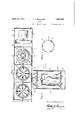
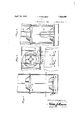
- Figure 1. is a tion, illhstrating; t a sign construction in accordancewith my invention; c Q w Fig rreQ is a sectionalview taken on the line 27-2 of Figure- 1- I v f i i c Figure 3 isa sectional'vievv til-k8ll:0l1 theline 33 ofFigzure 21' v Figure is a: detail sectional viewillustratingsthe color changing means for the char; acters.
- i 1' Figure 5 is a fragmentary sectionalview illustrati-ngjthe control for the penumat'ic operating means.
- a t v Fi'nr'e .6 is a fragmentary sectional view taken onthe' line 62-6 of Figure 5':
- Figure 7 is a; fragmentary elevation illus- Another ohj ectlofthis invention is the pre- I 1 c v its upper portionhentangularlyjto rem a ⁇ side elevation partly in sec-g trating the means for holding the comer means in any ofitsadjusted'positions.
- Figure '8 is a, fragmentary sectional vievv? illustrating a modified form of illuminating means for the characters.
- I y l Referring in etail to the drawings, A the numeral l'i-ndicatesfan elongated casing havin arranged therein vert-icall y, and.
- rod-1315 is secured to each electric lamp socket 8" and hast vertically disposed bearing pintle 12 disposed above the electric lamp and is received in: abearing "13 of. a color. ,changi-ng, shield 14s.;
- the shield 14 is of cylindrical formatiomthe Walls of which are constructed ofa plurali ty of color panels 15 riveted or othenwi se s e cured together as shown atlGQ Theshiel-d is disposed? about; the, electric" lamp 9 and has; secured in its upper end a wind wheel 14 the blades ofIWhi-ch are so disposed thatthepas-.
- The-pitch or shields and through their respective wind wheels angle of the blades of the different wind wheels may be varied for the purpose of caus ing one shield to rotate in one direction while the adjacent shield is rotated in an opposite direction.
- An elongated chamber 18 is formed on the bottom'of the casing 1 and is in communica tion with the lower compartment by open ings 19 and the chamber 18 at one end communicates with a fanchamber 20 formed in a housing 21 carrie'd'by one end of the'casing 1.
- An electrically driven fan 22 is mounted in the housing 21'with theblades thereof positioned in the fan chamber 20 so that during the rotation thereof air will be drawn.
- each compartment has a conical shaped deflector 24 mounted on the bottom wall thereof and about the air'openings of said comshields about partments and extendinginto the lower end: 7 ofithe shield for the purpose of deflecting 'the air passing through the openings into the shield.
- the upper vend of the casing 1 is closed by a removable cover25 including upper and lower sections 26 and 27 which areso connected and spaced from each other that the exhaust passages for the air escapingfrom atmosphere.
- the upper section 26 has its edges disposed lnwa'rdly of theedges of the lower section the upper compartments'may pass out to the 27 to'lprevent' weather elements from entering the casing but still permitting free exhaust of the air from the casing.
- a screen 28 of any' suitable material closes thelower section 27 for the purpose of preventing foreign matter'from entering the compart- V ments, should such matter, gam entrance to the interior of the cover V or between the scc-' 1 S2 and 27 thereof.
- Valve operating rods 29 are journaled in each compartment adjacent to the bottom walls thereof and extend outwardly of 'the rotated to vary the positions of the plates relative to the walls of the openings. Disks 31 are secured to the operating rods and are engaged by the free ends of leaf springs 32 for the purpose of holding the rods in any of their adjusted positions. thus it will be seen that means is provided whereby the passage of air through the compartments may be regulated consequently permitting the speed of rotation of the shields to be varied.
- a I V 7 Referring to my modified form of'invention as shown in Figure 8, the electric lamp sockets Sand electric lamps 9 may have neon tubes 83 substituted in lieu thereof andover' which the shields may operate.
- I i p A sign comprising a casing rows of compartments in said casing'and'the compartments of one row disposed above and in vertical alignment with the compartmentsof the other row and having communication with each other, illuminating means'in each compartment, character panels for eachcompartair passing throughsaid shields.
- a sign comprising a casing, rows of compartments in said casing and the compartments of one row disposed above and n vertical alignment withthe compartments of the other row andhaving communication with each other, illuminating meansin each compartment, character panels for each compartment, color varying shields associated with illuminating means and rotatably mounted,.means forcing air through the com-' partments and shields, and wind wheels secured to the shields for rotating the latter by the air passing through said shields.
- a sign comprising a casing, rows of compartments in said casing and the compartments of one row disposed above and in vertical alignment with the compartments of the other row and having communication with each other, illuminating means in each compartment, character panels for each compartment, color varying shields associated with illuminating means and 'rotatably mounted, means forcing air through the compartments and shields, wind wheels secured to the shields for rotating the latter by the air passing through said shields, and means for regulating the fiowof air throughsaid shields.
- a sign comprising a casing, rows of compartments in said casing and the compartments of one row disposed above and in vertical alignment with the compartments of the other row and having communication with each other, illuminating means in each compartment, character panels for each compartment, color varying shields associated with illuminating means and rotatably mounted, means forcing air through the compartments and shields, wind wheels secured to the shields for rotating the latter by the air passing through said shields, means for regulating the flow of air through said shields,-and deflectors for directing the air through the shields.
- a sign comprising a casing, rows of compartments in said casing and the compartments of one row disposed above and in vertical alignment with the compartments of the other row and having communication with each other, illuminating means in each compartment, character panels for each com partment, color varying shields associated mounted, means forcing air through the compartments and shields, wind wheels secured to the shields for rotating the latter by the air passing through said shields, means for regulating the flow of air through said shields, and deflectors for directing the air through the shields, and means for holding said regulating means in any of its adjusted positions.
- a sign comprising a casing, a pair of compartments in the casing and having communication with each other, characters associated with the compartments, illuminating means in each compartment, a color varying shield associated with each illuminating pressed air supply operating the color varying means.
- a sign COIIlpIlSlIlg a face having a translucent portion, illuminating means to the rear of said translucent portion, and com-.
- a sign comprising a casing having communicating compartments, illuminating means for each compartment, air operated color varying means associated with the illuminating means, means forcing air through said compartments to actuate the color vary-
Landscapes
- Physics & Mathematics (AREA)
- General Physics & Mathematics (AREA)
- Engineering & Computer Science (AREA)
- Theoretical Computer Science (AREA)
- Illuminated Signs And Luminous Advertising (AREA)
Description
April 12, 193-2. BERGGREN 1,853,399
SIGN I Filed March 2, 1951 3 Sheets-Sheet l cibhnllfierggren INVENTOR ATTORNEYS April 12, 1932. 'J. 1.. BERGGREN 1,353,399
SIGN
4 m ulu April 12, 1932. J. 1.. BERGGREN 1,853,399
SIGN
Filed March 2, 1931 3 Sheets-Sheet 3 cfohnlijiez'ggren/ ATTORNEY;
Patented Apr. 12, 1932 form n. eneeennn; or Dmmnms e SIGN Application filed March 2, 1931.; Serial--Noi 1-9,5 75 c This invention relates to improvements in display signs andhasifor the primary object; the provision. of means,(wv herehy the charactors one sign may: he aceentnated'to attract attention thereto by changing the color there: of, thus providinga device which will be extremely si mple in construction and cheap in maintenance and one which Will'he attractive so astoi afiord'maximunr display advantages.
vision. of an independent laminating means foreach character and equippeclwith means whereby the colors. of each character'may he i continually changed.
1'5 v .fiurthler. object ofth-is invention is the provision ofa pneumatic operating meansf-or the colon. changing mechanisms and which isso constructedthat the speed of'operation ofthe-l -;C0 10I1 changing mechanisms may be varied to 2V suit the taste of each individual user;
further object of this invention is the.
provision-0f asignof the above noted Chan,
actei; which: will he. simple; durable and eff. M- ficient and which may he manufactured and sold. atva comparatively l'ow cost'.
these and other objects i niview as Will become more apparent asthe description'pro ceeds, the invention consists in a certain novel arrangement-Lofparts as. wilhhehereinafter. more fully) descrihedfandclaimed; I
For a completeunderstandingjo-f myinvens tion,-re ference to hehadi to the following description ancl..,accom1panying v drawings, in
Figure 1.. is a tion, illhstrating; t a sign construction in accordancewith my invention; c Q w Fig rreQ is a sectionalview taken on the line 27-2 ofFigure- 1- I v f i i c Figure 3 isa sectional'vievv til-k8ll:0l1 theline 33 ofFigzure 21' v Figure is a: detail sectional viewillustratingsthe color changing means for the char; acters. i 1' Figure 5 is a fragmentary sectionalview illustrati-ngjthe control for the penumat'ic operating means. a t v Fi'nr'e .6 is a fragmentary sectional view taken onthe' line 62-6 of Figure 5':
Figure 7 "is" a; fragmentary elevation illus- Another ohj ectlofthis invention is the pre- I 1 c v its upper portionhentangularlyjto rem a} side elevation partly in sec-g trating the means for holding the comer means in any ofitsadjusted'positions.
Figure '8 is a, fragmentary sectional vievv? illustrating a modified form of illuminating means for the characters. I y l Referring in etail to the drawings, A the numeral l'i-ndicatesfan elongated casing havin arranged therein vert-icall y, and. horizom; tall-y disposedfpartitions-g for the purpose of divi'dingftlie: center of the casing into a phiral-ity of compartments 3,1;andhy referringito Fi ure I it, Willheinoted that compartments are arranged a in pairsvwithone-compartn ent of each pair "arran ed above the companion compartment compartments are in communication with each otherby; openings, l -fermedflin, the .HQIll: Zontal; partition. 'lhe side walls offenc sing 1 are provided with] windows aligning with the compartments andQcl'ose'd by transparent p anels 6' having;- applied thereto charactfers Hnan suitable manneri-g. a; a Each compartmenthas mountedon the "bottom Wallan electric lamps socket 8? to receive! anelectric lamp9 for the purposeofill-uminati'ng "the characters on the panels' iofi each, respective compartment;- The electricsockets 8" are 1 electrically connected togetherby condiuetors 10 adapted-t0 extend outwardlyofthe casing 1 to beattaehed inany ordi 80 nary manner with an electric source. c
vertically disposed: supporting! rod-1315 is secured to each electric lamp socket 8" and hast vertically disposed bearing pintle 12 disposed above the electric lamp and is received in: abearing "13 of. a color. ,changi-ng, shield 14s.; The shield 14 is of cylindrical formatiomthe Walls of which are constructed ofa plurali ty of color panels 15 riveted or othenwi se s e cured together as shown atlGQ Theshiel-d is disposed? about; the, electric" lamp 9 and has; secured in its upper end a wind wheel 14 the blades ofIWhi-ch are so disposed thatthepas-.
sage of air therethrough will cause rotation ofthe shield I4 about the electric lamp bringin'g' first on'e'color" stripj'or panel: align; ment' With thefwindows and then;another panel so as to continuously .changethe light rays from the lamps to the panels'th'erehy e pairs ot 5 "pintle 12 to engage thus permitting the shield to adjust itself to the lamp at all times during 1 its rotation about thelamp. The-pitch or shields and through their respective wind wheels angle of the blades of the different wind wheels may be varied for the purpose of caus ing one shield to rotate in one direction while the adjacent shield is rotated in an opposite direction. a v Y An elongated chamber 18 is formed on the bottom'of the casing 1 and is in communica tion with the lower compartment by open ings 19 and the chamber 18 at one end communicates with a fanchamber 20 formed in a housing 21 carrie'd'by one end of the'casing 1. An electrically driven fan 22 is mounted in the housing 21'with theblades thereof positioned in the fan chamber 20 so that during the rotation thereof air will be drawn.
into the housing 21 by way of the opening 23 A and forced through the fan housing into the chamber 18. The air under pressure in the chamber 18. passes upwardly through the lower compartments through theshields 14 and through the blades of the wind shields 15 causing rotation of the shields about the'ele'ctrio lamps. The air passing upwardly in the lower compartments, enter the upper compartments and passes upwardly through the located in said upper compartments causing rotation of the upper their respective electric'lamp. a
fEach compartment has a conical shaped deflector 24 mounted on the bottom wall thereof and about the air'openings of said comshields about partments and extendinginto the lower end: 7 ofithe shield for the purpose of deflecting 'the air passing through the openings into the shield.
The upper vend of the casing 1 is closed by a removable cover25 including upper and lower sections 26 and 27 which areso connected and spaced from each other that the exhaust passages for the air escapingfrom atmosphere. p The upper section 26 has its edges disposed lnwa'rdly of theedges of the lower section the upper compartments'may pass out to the 27 to'lprevent' weather elements from entering the casing but still permitting free exhaust of the air from the casing. A screen 28 of any' suitable material closes thelower section 27 for the purpose of preventing foreign matter'from entering the compart- V ments, should such matter, gam entrance to the interior of the cover V or between the scc-' 1 S2 and 27 thereof.
Valve operating rods 29 are journaled in each compartment adjacent to the bottom walls thereof and extend outwardly of 'the rotated to vary the positions of the plates relative to the walls of the openings. Disks 31 are secured to the operating rods and are engaged by the free ends of leaf springs 32 for the purpose of holding the rods in any of their adjusted positions. thus it will be seen that means is provided whereby the passage of air through the compartments may be regulated consequently permitting the speed of rotation of the shields to be varied. a I V 7 Referring to my modified form of'invention as shown in Figure 8, the electric lamp sockets Sand electric lamps 9 may have neon tubes 83 substituted in lieu thereof andover' which the shields may operate.
While I-have' shown and described the 'pr'eferred'embodiment vof my inventiom'it will be understood that minor changes in con struction, combination and arrangement of parts may be made without departing from the spirit and scope as claimed.
Having'thus described my invention, what Iclaimis: I i p 1. A sign comprising a casing rows of compartments in said casing'and'the compartments of one row disposed above and in vertical alignment with the compartmentsof the other row and having communication with each other, illuminating means'in each compartment, character panels for eachcompartair passing throughsaid shields. 1
2. A sign comprising a casing, rows of compartments in said casing and the compartments of one row disposed above and n vertical alignment withthe compartments of the other row andhaving communication with each other, illuminating meansin each compartment, character panels for each compartment, color varying shields associated with illuminating means and rotatably mounted,.means forcing air through the com-' partments and shields, and wind wheels secured to the shields for rotating the latter by the air passing through said shields.
3. A sign comprising a casing, rows of compartments in said casing and the compartments of one row disposed above and in vertical alignment with the compartments of the other row and having communication with each other, illuminating means in each compartment, character panels for each compartment, color varying shields associated with illuminating means and 'rotatably mounted, means forcing air through the compartments and shields, wind wheels secured to the shields for rotating the latter by the air passing through said shields, and means for regulating the fiowof air throughsaid shields.
4. A sign comprising a casing, rows of compartments in said casing and the compartments of one row disposed above and in vertical alignment with the compartments of the other row and having communication with each other, illuminating means in each compartment, character panels for each compartment, color varying shields associated with illuminating means and rotatably mounted, means forcing air through the compartments and shields, wind wheels secured to the shields for rotating the latter by the air passing through said shields, means for regulating the flow of air through said shields,-and deflectors for directing the air through the shields.
5. A sign comprising a casing, rows of compartments in said casing and the compartments of one row disposed above and in vertical alignment with the compartments of the other row and having communication with each other, illuminating means in each compartment, character panels for each com partment, color varying shields associated mounted, means forcing air through the compartments and shields, wind wheels secured to the shields for rotating the latter by the air passing through said shields, means for regulating the flow of air through said shields, and deflectors for directing the air through the shields, and means for holding said regulating means in any of its adjusted positions.
6. A sign comprising a casing, a pair of compartments in the casing and having communication with each other, characters associated with the compartments, illuminating means in each compartment, a color varying shield associated with each illuminating pressed air supply operating the color varying means.
9. A sign COIIlpIlSlIlg a face having a translucent portion, illuminating means to the rear of said translucent portion, and com-.
pressed air operated color varying means for said translucent portion associated withthe illuminating means. e In testimony whereof I afiix my signature.
' JOHN L. BERGrGrREN.
with illuminating means and rotatably means and rotatably mounted, means for rotating the shield by the passing of air through said shields, a conduit on the casing and in communication with one of the compart ments, a housing on said casing, a fan chamher in the housing and in communication with the conduit, an electric fan having the blades thereof in the fan chamber for forcing air through the conduit and through the compartments and shields located therein.
7 A sign comprising a casing having communicating compartments, illuminating means for each compartment, air operated color varying means associated with the illuminating means, means forcing air through said compartments to actuate the color vary-
Priority Applications (1)
| Application Number | Priority Date | Filing Date | Title |
|---|---|---|---|
| US519575A US1853399A (en) | 1931-03-02 | 1931-03-02 | Sign |
Applications Claiming Priority (1)
| Application Number | Priority Date | Filing Date | Title |
|---|---|---|---|
| US519575A US1853399A (en) | 1931-03-02 | 1931-03-02 | Sign |
Publications (1)
| Publication Number | Publication Date |
|---|---|
| US1853399A true US1853399A (en) | 1932-04-12 |
Family
ID=24068892
Family Applications (1)
| Application Number | Title | Priority Date | Filing Date |
|---|---|---|---|
| US519575A Expired - Lifetime US1853399A (en) | 1931-03-02 | 1931-03-02 | Sign |
Country Status (1)
| Country | Link |
|---|---|
| US (1) | US1853399A (en) |
-
1931
- 1931-03-02 US US519575A patent/US1853399A/en not_active Expired - Lifetime
Similar Documents
| Publication | Publication Date | Title |
|---|---|---|
| US1919922A (en) | Game projecting apparatus | |
| US1871742A (en) | Aquarium | |
| US1853399A (en) | Sign | |
| US859199A (en) | Apparatus for displaying illuminated multicolored signs or advertisements. | |
| US2204435A (en) | Animated display apparatus | |
| Nichol | Views of the Architecture of the Heavens: In a Series of Letters to a Lady | |
| US1740747A (en) | Electric-lighted display sign or emblem | |
| US2258560A (en) | Advertising pillar | |
| US2424169A (en) | Self-illuminated plastic plug-in alphabet blocks | |
| US1619096A (en) | Advertising-projecting device | |
| US2145747A (en) | Advertising apparatus | |
| US1374921A (en) | Mechanically-waved flag | |
| US1796903A (en) | Advertising device | |
| US1921570A (en) | Illuminated advertising sign | |
| US2010004A (en) | Sign | |
| US1777866A (en) | Display apparatus | |
| US2152845A (en) | Sign | |
| US1980665A (en) | Illuminated sign | |
| US2058312A (en) | Electrical advertising device | |
| US1715129A (en) | Sectional luminous animated outdoor billboard | |
| US1904132A (en) | Changeable illuminated display | |
| US1061520A (en) | Advertising and like apparatus. | |
| US1600966A (en) | Advertising device | |
| US1651429A (en) | Sign | |
| US242483A (en) | sisson |