US1853388A - Waterproof watch case construction - Google Patents
Waterproof watch case construction Download PDFInfo
- Publication number
- US1853388A US1853388A US506563A US50656331A US1853388A US 1853388 A US1853388 A US 1853388A US 506563 A US506563 A US 506563A US 50656331 A US50656331 A US 50656331A US 1853388 A US1853388 A US 1853388A
- Authority
- US
- United States
- Prior art keywords
- crown
- tube
- gasket
- bezel
- pendant
- Prior art date
- Legal status (The legal status is an assumption and is not a legal conclusion. Google has not performed a legal analysis and makes no representation as to the accuracy of the status listed.)
- Expired - Lifetime
Links
- 238000010276 construction Methods 0.000 title description 20
- 238000004804 winding Methods 0.000 description 22
- 239000013078 crystal Substances 0.000 description 21
- 210000004247 hand Anatomy 0.000 description 4
- 230000000694 effects Effects 0.000 description 3
- 239000000463 material Substances 0.000 description 3
- 239000002184 metal Substances 0.000 description 3
- 210000000707 wrist Anatomy 0.000 description 3
- 238000004519 manufacturing process Methods 0.000 description 2
- 230000032683 aging Effects 0.000 description 1
- 239000000428 dust Substances 0.000 description 1
- 230000002452 interceptive effect Effects 0.000 description 1
- 238000012986 modification Methods 0.000 description 1
- 230000004048 modification Effects 0.000 description 1
- 238000012856 packing Methods 0.000 description 1
- 229920000136 polysorbate Polymers 0.000 description 1
- XLYOFNOQVPJJNP-UHFFFAOYSA-N water Substances O XLYOFNOQVPJJNP-UHFFFAOYSA-N 0.000 description 1
Images

Classifications
-
- G—PHYSICS
- G04—HOROLOGY
- G04B—MECHANICALLY-DRIVEN CLOCKS OR WATCHES; MECHANICAL PARTS OF CLOCKS OR WATCHES IN GENERAL; TIME PIECES USING THE POSITION OF THE SUN, MOON OR STARS
- G04B37/00—Cases
- G04B37/08—Hermetic sealing of openings, joints, passages or slits
- G04B37/10—Hermetic sealing of openings, joints, passages or slits of winding stems
- G04B37/103—Hermetic sealing of openings, joints, passages or slits of winding stems by screwing the crown onto the case
-
- G—PHYSICS
- G04—HOROLOGY
- G04B—MECHANICALLY-DRIVEN CLOCKS OR WATCHES; MECHANICAL PARTS OF CLOCKS OR WATCHES IN GENERAL; TIME PIECES USING THE POSITION OF THE SUN, MOON OR STARS
- G04B37/00—Cases
- G04B37/08—Hermetic sealing of openings, joints, passages or slits
- G04B37/081—Complete encasings for wrist or pocket watches also comprising means for hermetic sealing of the winding stem and crown
Definitions
- This invention relates to watch case construction and more particularly to watchcase construction incorporating waterproof or otherwise interfering with the accurateoperation of the movement.
- Another object of my invention is to reumble to a minimum the number of parts necessary in the construction of waterproof watchcases.
- the watchcase of the present invention is characterized by the fact that odd-shaped cases, crystals and bezel openings can equally well be'manufactured without destroying any of the principles of construction which form the subject of the invention.
- shaped case desired is of no moment as the bezel can be made of any desired shape and likewise the crystal without changing or .modifying the waterproof construction in the least.
- Fig. 1 is a side elevation of a wrist watch case illustrated by partial section and shown on a greatly enlarged or exaggerated scale;
- - Fi 2 is an isometric view of Fig. 1, the bracdlet, lugs, crown and its associated parts being omitted and a portion of the view broken away to clearly illustrate the characteristic parts of one embodiment of the invention;
- Fig. la is a fragmentary sectional view similar to the right hand side of Fig. 1 but showing a modified construction
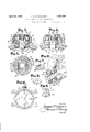
- Figs. 3 and 4 respectively, illustrate in section two difierent positions of the waterproof crown and tube
- Fig. 5 is a horizontal section taken on a plane corresponding to line 5-5 of Fig. 3;
- Fig. 6 is a fragmentary isometric sectional view, on a greatly enlarged or exaggerated scale, in the vicinity of the pendant tube 15, the winding stem 26, crown 22 and crown gasket 21 being omitted;
- Fig. 'Z is an isometrioview of the locking nut 29;
- Fig. 8 is an isometric view of the crown gasket
- Fig. 9 is an isometric view of the pendant tube 15 shown in an inverted position.
- Fig. 10 is a face view of a wrist watchcase made in accordance with the present invention.
- the bezel 1 in the resent instance is cylindrical in form and is provided with an internal screw thread 7 to receive the corresponding external screw thread 8 of locking ring 3. If, as shown in Fig.1, the case is to be used as a wrist watch the bezel 1 is rovided with bracelet holding lugs 9, whic lu can be formed as an inte 1 part of sai bezel or suitably attached ereto, as desired, to form a rigid unit. .
- the u per portion of bezel 1 is flared inwardly and terminates in the form of circular horizontal flange 10. This flange 10 engages the flange 5a of crystal 5 in a manner presently to be described.
- the combination back and center 2 comprises a cylindrical cup-sha ed member, the u standing wall 11 of which is provided with the usual seating for supportin a movement, as shown at 13, the movement eing designated 12.
- the upper ed e 14 of wall 11 artially sup orts the flexib e gasket 6, whic will be exp ained more fully as the description proceeds.
- FIG. 20 designates a'circular horizontal flange formed as an integral part of the tube 15 and serves as a support for the crown gasket 21.
- This gasket 21 fits between the flange 20 of ndant tube 15 and the crown 22, as clearly s own in Figs. 3 and 4, respectivel Cylindrical core 23, formed integral with t e crown 22, extends inwardly from the top of the latter and is provided with a right-hand internal screwthread 24 to receive the right-hand externally threaded portion 25 of winding stem 26.
- Crown 22 is further provided with a lefthand internal screw thread 27 which is adapted to receive a corresponding external screwthread 28 formed. upon the locking nut 29. This locking nut 29 is shown in detail in Fig.
- the first step is that of placing the locking nut 29 upon the pendant tube 15 so that the walls 18 of said tube are received by the rectangular central openin 30 of said locking nut. Then the inner en of said tube is rigidly connected to the outer periphery of wall 11 of the combinationback and center 2 by the soldered joint 17, as before stated and in such a manner that the hole 19 of said tube is in alinement with opening 16 of said wall, as clearly illustrated by Fig. 6.
- the locking nut 29 is 'free to have an axial movement upon said tube between the flange 20 of said tube and said wall 11 but is prevented from rotation upon the tube due to the rectangular central opening 30 thereof engaging the walls 18 of said tube.
- the winding stem 26 is gassed into the winding stem material 31 an said material and stem inserted through the opening 16 in wall 11 and into the hole 19 in pendant tube 15.
- crown gasket 21 is placed upon flange 20 of said endant tube 15.
- Crown 22 is then attache to the winding stem 26 by screwing the right-hand internal screw thread 24 of core 23 upon the right-hand externally threaded portion 25 of said stem.
- the movement 12 is placed within the combined back and center 2, as shown in Fig. 1 and the dial 4, gasket 6 and crystal 5 placed thereon in the order mentioned.
- Bezel 1 is then laced over the wall 11 of combined back an center 2, the pendant tube 15 bein received by the opening 32 (Fig. 2) in sai bezel and the flange 10 of said bezel engaging the flange 5a of crystal 5, as clearlvshown in Figs. 1, 2 and 6, respectively.
- cking ring 3 is then screwed within the bezel 1 by means of its external screw thread 8 en aging the internal screw screwed home within the bezel 1 it engages the back 2 and forces it upwardly or in a direction towards the crystal 5, thus causing the movement 12 to bear a ainst the dial 4, the dial 4 and the upper e go 14 of wall 11, in turn, against the gasket 6, the gasket 6 in turn against the flange 5a of crystal 5 and the flange 5a of crystal 5 in turn against one side of flan e 10 of bezel 1.
- 0 parts a water-tight joint is provided between the combined back and center 2 and the crystal 5 by means of the gasket 6 being tightly wedged therebetween.
- the crown 22 is brought to the position shown in nasaass Fig. 8 by rotating it in the reverse direction to that' of winding. This rotation of the crown 22 causes the locking nut 29 to be unscrewed from the crown, as shown in Fig. 3, whereupon winding canbe efiected'an'd the hands set.
- a watchcase oi waterproof construction comprising the combination of a cupshaped combination back and center adapt ed to receive and support a watch movement, a dial supported by said movement and adapted to have its outer face flush with the edge of said center, a gasket supported by said center and'dial, a crystal, a flange on said crystal adapted to rest upon said gasket, a
- bezel adapted to fit over said center, a flange on said bezel and a locking ring having screwthreaded engagement with said bezel whereby when said ring is screwed home within said bezel it is adapted to enga c said back, thereby drawing the flange 0 said bezel against the flange of said crystal, the fian e o said crystal a ainst said gasket, and t e gasket against said dial and center to therey effect a water-ti ht joint between said crystal and center, su stantially as described.
- a waterproof watchcase construction comprising, in combination, movement holding means adapted to receive and sup ort a watch movement, a bezel adapted to t over said movement holding means, a crystal, a gasket, means adapted to draw said bezel and movement holding means towards one another to wedge the crystal and gasket therebetween, a.
- crown therefor comprising a pendant tube fixed to said case, a winding stem rotatably mounted within the tube, a crown gasket supported by the upper ortion of said tube, a crown screwed upon t e winding stem, an 1nternal thread formed upon said crown, a locking nut received over said tube and ca able of having axial movement thereon whi e at the same time held against rotation with respect to said tube, an external thread on said nut adapted to be engaged with the internal thread on said crown to thereby compress said gasket between said tube and crown to effect a water-tight joint therebetween.
- awaterproof pendant and crown therefor comprising a pendant tube rigidly attached to a part of said case and aving a central bore adapted to be in alinement with an opening in said case, a flange formed integral with the outer end of said tube, a looking nut received over said tube and held against rotation thereon but being free for axial movement between said flange of said tube and said case, an external screw thread on the periphery of said nut, a winding stem rotatably mounted within the tube, a crown screwed upon the winding stem, a gasket located between the flange of said tube and said crown and an internal thread upon said crown adapted to be engaged with the external thread of said nut whereby when said nut is screwed home within said crown said gasket will be tightly pressed between said crown and the flange upon said tube to thereby insure a water-tight joint therebetween.
- a watchcase having, in combination, a waterproof pendant and crown comprising a pendant member mounted so as to be integrally connected to a art of the watch casmg and provided with a hole extending throughout its length, a windin stem received within the hole in said en ant member, a windin crown detacha 1 connected to and adapte to actuate said winding stem and having a recess, asket means located between said crown and pendant member, locking means for said crown free to move axially upon said pendant member but held against rotation thereof and means capable of drawing said locking means within said recess when the crown is rotated in a reverse direction to that of winding the watch to thereby tightly wedge said gasket means between said crown and pendent member when a watergcrown tight joint is desired between said crown and pendant member.
- watch case of a waterproof pendant and crown therefor comprising a pendant tube fixed to a part of said case, a winding stem received within the tube, a crown gasket supported by said tube, a crown screwed upon the winding stem, a locking member received over said tube and capable of having axial movement thereon while at the same time held against rotation relative to said tube, means formed upon said crown for adjustable attachment with said nut, means on said nut adapted to engage with the means on said crown to draw said nut within said crown, thereby compressing said gasket between said tube and crown to efiect a watertight ioint therebetween.
- watchcase having, in combination, a waterproof pendant and crown comprising a pendant member mounted in such a manner as to be integrally connected to a part of the watch casin and provided with a hole bored longitudina y therethrough, a wind-
Landscapes
- Physics & Mathematics (AREA)
- General Physics & Mathematics (AREA)
- Electric Clocks (AREA)
Description
April 12, 1932. A w. WADSWORTH WATERPROOF WATCH CASE CONSTRUCTION Filed Jan. 5, 1931 2 Sheets-Sheet I N VEN TOR.
ATTORNEY.
ATTORNEY.
April 12, 1932. A w WADSWORTH WATERPROOF WATCH-CASE CONSTRUCTION Filed Jan 5, 1931 2 Sheets-Sheet 2 Patented 12, 1932 UNITED STATES PATENT OFFICE ARTHUR W. WADSWORTH, OF FORT THOMAS, KENTUCKY, ASSIGNOR TO THE WADS- WORTH WATCH CASE COMPANY, OF DAYTON, KENTUCKY, A CORPORATION OF KENTUCKY WATERPROOF WATCH CONSTRUCTION Application filed January 5, 1931. Serial No. 506,568. I
This invention relates to watch case construction and more particularly to watchcase construction incorporating waterproof or otherwise interfering with the accurateoperation of the movement.
Another object of my invention is to re duce to a minimum the number of parts necessary in the construction of waterproof watchcases. The watchcase of the present invention is characterized by the fact that odd-shaped cases, crystals and bezel openings can equally well be'manufactured without destroying any of the principles of construction which form the subject of the invention.
An attempt to produce a watch case of water-tight construction has heretofore been made by many different means, such as covers, packing and the like, but none of such means has given entire satisfaction some being too complicated and costly in their manufacture and others inadequate or not sufiiciently practical to satisfy the requirements of a truly waterproof case and, further, for the reason that the so-called heretofore waterproof watchcases have been limited to round shapes and always to round shaped bezel openings and crystals.
With the present invention, however, the
shaped case desired is of no moment as the bezel can be made of any desired shape and likewise the crystal without changing or .modifying the waterproof construction in the least.
With these and other objects, not specifi cally mentioned, in view, the invention consists in certain combinations, construction and arrangement of parts which will be hereinafter described and specifically pointed out in the claims.
Referring to the drawings which form a part of this specification:
Fig. 1 is a side elevation of a wrist watch case illustrated by partial section and shown on a greatly enlarged or exaggerated scale;
- Fi 2 is an isometric view of Fig. 1, the bracdlet, lugs, crown and its associated parts being omitted and a portion of the view broken away to clearly illustrate the characteristic parts of one embodiment of the invention;
Fig. la is a fragmentary sectional view similar to the right hand side of Fig. 1 but showing a modified construction;
Figs. 3 and 4, respectively, illustrate in section two difierent positions of the waterproof crown and tube;
Fig. 5 is a horizontal section taken on a plane corresponding to line 5-5 of Fig. 3;
Fig. 6 is a fragmentary isometric sectional view, on a greatly enlarged or exaggerated scale, in the vicinity of the pendant tube 15, the winding stem 26, crown 22 and crown gasket 21 being omitted;
Fig. 'Z is an isometrioview of the locking nut 29;
Fig. 8 is an isometric view of the crown gasket;
Fig. 9 is an isometric view of the pendant tube 15 shown in an inverted position; and
Fig. 10 is a face view of a wrist watchcase made in accordance with the present invention.
In the embodiment of my invention as illustrated and which shows a preferred construciii shown in Figs. 1 and 6, respectively. The bezel 1, in the resent instance is cylindrical in form and is provided with an internal screw thread 7 to receive the corresponding external screw thread 8 of locking ring 3. If, as shown in Fig.1, the case is to be used as a wrist watch the bezel 1 is rovided with bracelet holding lugs 9, whic lu can be formed as an inte 1 part of sai bezel or suitably attached ereto, as desired, to form a rigid unit. .The u per portion of bezel 1 is flared inwardly and terminates in the form of circular horizontal flange 10. This flange 10 engages the flange 5a of crystal 5 in a manner presently to be described.
As shown in Fig. 1, and again in Fig. 2, the combination back and center 2 comprises a cylindrical cup-sha ed member, the u standing wall 11 of which is provided with the usual seating for supportin a movement, as shown at 13, the movement eing designated 12. The upper ed e 14 of wall 11 artially sup orts the flexib e gasket 6, whic will be exp ained more fully as the description proceeds.
The description thus far deals with the case construction onl but in order to produce a waterproof watc case it is necessary tohave the crown and pendant tube water-tight also. This I have accomplished by the construction shown in Figs. 3 and 4. By an examination of these figures in connection with Fig. 6, it will be seen that the inner end of pendant tube 15 is attached to wall 11 of combination back and center 2 by a soldered joint 17, or the equivalent, thus fixin the tube 15 as an inte al part of the wa l 11.- A detail of this ti 15 is shown in Fig. 9, where it will be observed that the outside thereof is rectangular in shape, forming vertical walls 18, while the center is bored out to form hole 19. 20 designates a'circular horizontal flange formed as an integral part of the tube 15 and serves as a support for the crown gasket 21. This gasket 21 fits between the flange 20 of ndant tube 15 and the crown 22, as clearly s own in Figs. 3 and 4, respectivel Cylindrical core 23, formed integral with t e crown 22, extends inwardly from the top of the latter and is provided with a right-hand internal screwthread 24 to receive the right-hand externally threaded portion 25 of winding stem 26. Crown 22 is further provided with a lefthand internal screw thread 27 which is adapted to receive a corresponding external screwthread 28 formed. upon the locking nut 29. This locking nut 29 is shown in detail in Fig. 7 and is rovided with a central opening 30, rectangu ar in shape and of a size suitable for slidably fitting over the walls 18 of pendant tube 15, as shown in Fig. 6. In this figure the upstanding wall 11 of combined back and center 2 is shown rovided with a cylindrical o ning 16, the iameter ofwhich opening is e same as the diameter of the bored hole 19 in the pendant tube 15. This openin serves to receive the winding stem materia 31, as shown in Figs. 3 and 4, respectively, which material is well known to those skilled in the art of watchcase manufacture and has no bearin on the resent invention.
1 assem ling a watchcase made in accordance with my invention the first step is that of placing the locking nut 29 upon the pendant tube 15 so that the walls 18 of said tube are received by the rectangular central openin 30 of said locking nut. Then the inner en of said tube is rigidly connected to the outer periphery of wall 11 of the combinationback and center 2 by the soldered joint 17, as before stated and in such a manner that the hole 19 of said tube is in alinement with opening 16 of said wall, as clearly illustrated by Fig. 6. With the pendant tube 15 thus permanently attached to the wall 11 of combination back and center 2, the locking nut 29 is 'free to have an axial movement upon said tube between the flange 20 of said tube and said wall 11 but is prevented from rotation upon the tube due to the rectangular central opening 30 thereof engaging the walls 18 of said tube. Then the winding stem 26 is gassed into the winding stem material 31 an said material and stem inserted through the opening 16 in wall 11 and into the hole 19 in pendant tube 15. Then crown gasket 21 is placed upon flange 20 of said endant tube 15. Crown 22 is then attache to the winding stem 26 by screwing the right-hand internal screw thread 24 of core 23 upon the right-hand externally threaded portion 25 of said stem. Next, the movement 12 is placed within the combined back and center 2, as shown in Fig. 1 and the dial 4, gasket 6 and crystal 5 placed thereon in the order mentioned. Bezel 1 is then laced over the wall 11 of combined back an center 2, the pendant tube 15 bein received by the opening 32 (Fig. 2) in sai bezel and the flange 10 of said bezel engaging the flange 5a of crystal 5, as clearlvshown in Figs. 1, 2 and 6, respectively. cking ring 3 is then screwed within the bezel 1 by means of its external screw thread 8 en aging the internal screw screwed home within the bezel 1 it engages the back 2 and forces it upwardly or in a direction towards the crystal 5, thus causing the movement 12 to bear a ainst the dial 4, the dial 4 and the upper e go 14 of wall 11, in turn, against the gasket 6, the gasket 6 in turn against the flange 5a of crystal 5 and the flange 5a of crystal 5 in turn against one side of flan e 10 of bezel 1. By this arrangement 0 parts a water-tight joint is provided between the combined back and center 2 and the crystal 5 by means of the gasket 6 being tightly wedged therebetween.
To wind the watch or set the hands the crown 22 is brought to the position shown in nasaass Fig. 8 by rotating it in the reverse direction to that' of winding. This rotation of the crown 22 causes the locking nut 29 to be unscrewed from the crown, as shown in Fig. 3, whereupon winding canbe efiected'an'd the hands set. p
To effect a waterproof joint between the crown and tube, it is merely necessary'to press the crown 22 slightly towards the case and rotate it in a direction opposite to that of winding the watch, to screw the locking nut 29 home within the crown and against the flange 20 of pendant tube15. When said locking nut 29 is thus screwed home-within the crown 22, as shown in Fig. 4, the crown gasket, 21 is tightly compressed or wedged tween the flange 20 of said pendant tube 15 and the top of said crown 22, thus effecting a water-tight joint between said crown and tube, as will be clearlli nation of Fi 4. e usual setting mechanism of the pull t is, therefore, not interrupted or modi ed in its action in any way whatsoever by the water roof construction of the crown and tube, us to the fact that when the locking nut 29 is disengaged and separated from the crown 22 as shown in Fig. 3, the crown can be mampulated for winding the watch or setting the hands in 9 the usual manner. When winding of the watch or setting of the hands has been accomplished to the satisfaction of the user, all that is necessary to make the crown and tube water-tight is to press against the crown, thus moving it slight y towards the case, due to the natural pump in the stem and rotate the crown .in an anti-clockwise direction, or in a direction opposite to that of winding the watch, whereupon the locking nut 29 will be 40 drawn within the crown and against the flange 20 of the pendant tube 15, as above described.
In the event that crystal 5 should become broken, all that is necessary to remove it is to unscrew locking ring 3 from the bezel l,
whereupon said bezel 1 can be removed and a new crystal inserted, the bezel being then replaced and the locking ring 3 again screwed therein, in the manner heretofore explained. 59 By actual severe tests a watchoase constructed in the foregoing manner has proven to be moisture and dust proof beyond any doubt.
While I have shownand described one particular embodiment of my invention, it is to be understood that I contemplate certain changes and modifications without departing from the scope or spirit thereof as, for example, in Fig. la I have shown a modified 60 case construction wherein the back and center are shown as two separate parts, the movement 120. being locked within the center 2a by the customary case screws 12b and the back 2b having an external screw-thread 20 adapted to be received by an internal screw apparent upon exami thread 21! formed within the bezel 1a, as shown. With thisconstruction it is necessary to provide a pliable gasket 66 and a thin metal gasket 60 between said back 2?) and center 2a in addition to the pliable, gasket 6a between the center 2a, dial 4a and crystal 5?).
With a construction such as shown in Fig. 1a, employing two gaskets 6a and 6b, it becomes necessary to sup 1y a metal gasket 60 between the back 2?) an the gasket 66, due to the fact that said back, when screwed within the bezel 1a, would have a tendency to tear the gasket 612 without the metal gasket 60 being inserted between said gasket and said back.- This construction also eliminates the necessity of the locking ring 3 as the back 2?; serves not onl as a back but as a locking member for tig tly drawin the bezel 1a against the crystal 5b as wil be clearly apparent from an examination of Fig. 1a.
Having thus described my invention, what I claim as new and desire to secure by Letters Patent is:
1. A watchcase oi waterproof construction comprising the combination of a cupshaped combination back and center adapt ed to receive and support a watch movement, a dial supported by said movement and adapted to have its outer face flush with the edge of said center, a gasket supported by said center and'dial, a crystal, a flange on said crystal adapted to rest upon said gasket, a
bezel adapted to fit over said center, a flange on said bezel and a locking ring having screwthreaded engagement with said bezel whereby when said ring is screwed home within said bezel it is adapted to enga c said back, thereby drawing the flange 0 said bezel against the flange of said crystal, the fian e o said crystal a ainst said gasket, and t e gasket against said dial and center to therey effect a water-ti ht joint between said crystal and center, su stantially as described.
2. A waterproof watchcase construction comprising, in combination, movement holding means adapted to receive and sup ort a watch movement, a bezel adapted to t over said movement holding means, a crystal, a gasket, means adapted to draw said bezel and movement holding means towards one another to wedge the crystal and gasket therebetween, a. pendant tube fixed to said movement holding means and received through an opening in said bezel, a crown, a winding stem carried thereby and adapted to move therewith, a flange on said pendant tube, a gasket located between said flange and said crown, a locking nut capable of axial movement upon said tube but prevented from to tating thereon, an external screw thread on said locking nut and an internal screw thread on said crown whereby when said crown is rotated in an opposite direction to that of winding, said locking nut is drawn within said crown to engage the flange of said tube,
crown therefor comprising a pendant tube fixed to said case, a winding stem rotatably mounted within the tube, a crown gasket supported by the upper ortion of said tube, a crown screwed upon t e winding stem, an 1nternal thread formed upon said crown, a locking nut received over said tube and ca able of having axial movement thereon whi e at the same time held against rotation with respect to said tube, an external thread on said nut adapted to be engaged with the internal thread on said crown to thereby compress said gasket between said tube and crown to effect a water-tight joint therebetween.
4. In combination with a watchcase, awaterproof pendant and crown therefor comprising a pendant tube rigidly attached to a part of said case and aving a central bore adapted to be in alinement with an opening in said case, a flange formed integral with the outer end of said tube, a looking nut received over said tube and held against rotation thereon but being free for axial movement between said flange of said tube and said case, an external screw thread on the periphery of said nut, a winding stem rotatably mounted within the tube, a crown screwed upon the winding stem, a gasket located between the flange of said tube and said crown and an internal thread upon said crown adapted to be engaged with the external thread of said nut whereby when said nut is screwed home within said crown said gasket will be tightly pressed between said crown and the flange upon said tube to thereby insure a water-tight joint therebetween.
5. The combination with a waterproof Lsqaaas ly' upon said pendant member but held against rotation upon the latter, and means.
capable of drawing said locking meanswith in said crown to thereby tightly compress said waterproof means between said crown and pendant member to insure a water-tight joint between'said crown and last-mentioned member.
7. A watchcase having, in combination, a waterproof pendant and crown comprising a pendant member mounted so as to be integrally connected to a art of the watch casmg and provided with a hole extending throughout its length, a windin stem received within the hole in said en ant member, a windin crown detacha 1 connected to and adapte to actuate said winding stem and having a recess, asket means located between said crown and pendant member, locking means for said crown free to move axially upon said pendant member but held against rotation thereof and means capable of drawing said locking means within said recess when the crown is rotated in a reverse direction to that of winding the watch to thereby tightly wedge said gasket means between said crown and pendent member when a watergcrown tight joint is desired between said crown and pendant member.
ARTHUR W. WADSWORTH.
watch case, of a waterproof pendant and crown therefor comprising a pendant tube fixed to a part of said case, a winding stem received within the tube, a crown gasket supported by said tube, a crown screwed upon the winding stem, a locking member received over said tube and capable of having axial movement thereon while at the same time held against rotation relative to said tube, means formed upon said crown for adjustable attachment with said nut, means on said nut adapted to engage with the means on said crown to draw said nut within said crown, thereby compressing said gasket between said tube and crown to efiect a watertight ioint therebetween.
6. watchcase having, in combination, a waterproof pendant and crown comprising a pendant member mounted in such a manner as to be integrally connected to a part of the watch casin and provided with a hole bored longitudina y therethrough, a wind-
Priority Applications (1)
| Application Number | Priority Date | Filing Date | Title |
|---|---|---|---|
| US506563A US1853388A (en) | 1931-01-05 | 1931-01-05 | Waterproof watch case construction |
Applications Claiming Priority (1)
| Application Number | Priority Date | Filing Date | Title |
|---|---|---|---|
| US506563A US1853388A (en) | 1931-01-05 | 1931-01-05 | Waterproof watch case construction |
Publications (1)
| Publication Number | Publication Date |
|---|---|
| US1853388A true US1853388A (en) | 1932-04-12 |
Family
ID=24015120
Family Applications (1)
| Application Number | Title | Priority Date | Filing Date |
|---|---|---|---|
| US506563A Expired - Lifetime US1853388A (en) | 1931-01-05 | 1931-01-05 | Waterproof watch case construction |
Country Status (1)
| Country | Link |
|---|---|
| US (1) | US1853388A (en) |
Cited By (9)
| Publication number | Priority date | Publication date | Assignee | Title |
|---|---|---|---|---|
| US2765614A (en) * | 1953-03-17 | 1956-10-09 | Steimann Hans-Jean | Watch case |
| US2865163A (en) * | 1952-04-15 | 1958-12-23 | Elgin Nat Watch Co | Electrically-powered time device |
| US3453820A (en) * | 1966-05-03 | 1969-07-08 | John Simon | Fastening of timepiece movement |
| FR2021355A1 (en) * | 1968-10-23 | 1970-07-24 | Omega Brandt & Freres Sa Louis | |
| DE1673667B2 (en) * | 1966-07-21 | 1971-10-14 | Meyer & Co Ag | SCREW-IN CROWN FOR WATCHES |
| US3714775A (en) * | 1971-05-27 | 1973-02-06 | M Aoki | Waterproof watch with interlocking crystal support ring and movement support ring |
| US5598383A (en) * | 1994-11-17 | 1997-01-28 | Li; Tai H. | Watch with double thread coupling device |
| WO1999035541A3 (en) * | 1998-01-10 | 1999-09-16 | Rolf Kindermann | Time measuring device |
| US20110051564A1 (en) * | 2009-08-28 | 2011-03-03 | Haruki Hiranuma | Windup portable timepiece and method of operating crown with which this timepiece is equipped |
-
1931
- 1931-01-05 US US506563A patent/US1853388A/en not_active Expired - Lifetime
Cited By (9)
| Publication number | Priority date | Publication date | Assignee | Title |
|---|---|---|---|---|
| US2865163A (en) * | 1952-04-15 | 1958-12-23 | Elgin Nat Watch Co | Electrically-powered time device |
| US2765614A (en) * | 1953-03-17 | 1956-10-09 | Steimann Hans-Jean | Watch case |
| US3453820A (en) * | 1966-05-03 | 1969-07-08 | John Simon | Fastening of timepiece movement |
| DE1673667B2 (en) * | 1966-07-21 | 1971-10-14 | Meyer & Co Ag | SCREW-IN CROWN FOR WATCHES |
| FR2021355A1 (en) * | 1968-10-23 | 1970-07-24 | Omega Brandt & Freres Sa Louis | |
| US3714775A (en) * | 1971-05-27 | 1973-02-06 | M Aoki | Waterproof watch with interlocking crystal support ring and movement support ring |
| US5598383A (en) * | 1994-11-17 | 1997-01-28 | Li; Tai H. | Watch with double thread coupling device |
| WO1999035541A3 (en) * | 1998-01-10 | 1999-09-16 | Rolf Kindermann | Time measuring device |
| US20110051564A1 (en) * | 2009-08-28 | 2011-03-03 | Haruki Hiranuma | Windup portable timepiece and method of operating crown with which this timepiece is equipped |
Similar Documents
| Publication | Publication Date | Title |
|---|---|---|
| US1853388A (en) | Waterproof watch case construction | |
| US2497935A (en) | Dust-tight watch crown | |
| US3355873A (en) | Watertight shaped watch | |
| US3271945A (en) | Watch casing with rotatable bezel | |
| US4313187A (en) | Water resisting crown structure for electronic wristwatches | |
| US1910908A (en) | Watchcase | |
| US3535869A (en) | Water-tight winding stem for a timepiece | |
| US2350651A (en) | Watchcase | |
| US3735584A (en) | Shock-resistant watchcase for a portable watch | |
| US3499281A (en) | Watch crown | |
| US3614865A (en) | Watch-case with a watertight winding crown | |
| US2719403A (en) | Tight container | |
| US2338343A (en) | Watch crystal assembly tool | |
| US4059957A (en) | Water-tight fitting of a glass in a watch case | |
| CH160803A (en) | Self-winding timepiece. | |
| US2445578A (en) | Joint for tubes | |
| US3261159A (en) | Water resistant watch case | |
| US2589052A (en) | Watch winding and setting mechanism | |
| US2302340A (en) | Waterproof watchcase | |
| US2405087A (en) | Tight winding device for timepieces | |
| US2587087A (en) | Tight watchcase | |
| US2773347A (en) | Winding crown for timepiece movement | |
| US4502791A (en) | Water-resistant device between an outside control member and a watch case | |
| US2229979A (en) | Watchcase | |
| US2727354A (en) | Water, shock and dustproof watchcase |