US1853381A - Mechanical control apparatus - Google Patents
Mechanical control apparatus Download PDFInfo
- Publication number
- US1853381A US1853381A US452372A US45237230A US1853381A US 1853381 A US1853381 A US 1853381A US 452372 A US452372 A US 452372A US 45237230 A US45237230 A US 45237230A US 1853381 A US1853381 A US 1853381A
- Authority
- US
- United States
- Prior art keywords
- movement
- shaft
- pin
- cam
- spring
- Prior art date
- Legal status (The legal status is an assumption and is not a legal conclusion. Google has not performed a legal analysis and makes no representation as to the accuracy of the status listed.)
- Expired - Lifetime
Links
- 238000010276 construction Methods 0.000 description 3
- RTZKZFJDLAIYFH-UHFFFAOYSA-N Diethyl ether Chemical compound CCOCC RTZKZFJDLAIYFH-UHFFFAOYSA-N 0.000 description 2
- 230000000737 periodic effect Effects 0.000 description 2
- 241000282326 Felis catus Species 0.000 description 1
- 239000003415 peat Substances 0.000 description 1
- 230000002093 peripheral effect Effects 0.000 description 1
- 238000004804 winding Methods 0.000 description 1
Images
Classifications
-
- G—PHYSICS
- G05—CONTROLLING; REGULATING
- G05G—CONTROL DEVICES OR SYSTEMS INSOFAR AS CHARACTERISED BY MECHANICAL FEATURES ONLY
- G05G15/00—Mechanical devices for initiating a movement automatically due to a specific cause
- G05G15/04—Mechanical devices for initiating a movement automatically due to a specific cause due to distance or angle travelled by a member
-
- Y—GENERAL TAGGING OF NEW TECHNOLOGICAL DEVELOPMENTS; GENERAL TAGGING OF CROSS-SECTIONAL TECHNOLOGIES SPANNING OVER SEVERAL SECTIONS OF THE IPC; TECHNICAL SUBJECTS COVERED BY FORMER USPC CROSS-REFERENCE ART COLLECTIONS [XRACs] AND DIGESTS
- Y10—TECHNICAL SUBJECTS COVERED BY FORMER USPC
- Y10T—TECHNICAL SUBJECTS COVERED BY FORMER US CLASSIFICATION
- Y10T74/00—Machine element or mechanism
- Y10T74/18—Mechanical movements
- Y10T74/18056—Rotary to or from reciprocating or oscillating
- Y10T74/18216—Crank, lever, and slide
Definitions
- One of the objects of my invention isto LE provide a construction of automatic time controlled reversing mechanism whereby the position of an' actuating member may be changed quickly at the end of a predetermined time interval.
- Another object of my invention is to pro- 'vide a compact arrangement of gears and reversing mechanism by which the movement of a pin may be controlled over a predetermined time interval for bringing out a quick snap action for the reversing of an associated mechanical member.
- Still another object of my invention is to provide a mechanism having means for automatically storing energy in a spring device for a periodic action for producing reciprocative movement from a continuous rotative movement.
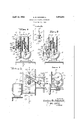
- Figure 1 is a side elevation of the mechanical movement of my invention
- Fig.2 is a longitudinal cross-sectional view through the actuating mechanism on line 2-2 of Fig. 1 showing the actuating mechanism in one position
- Fig. 3 is a cross-sectional view of the actuating mechanism illustrated in Fig. 2 but removed to an extreme opposite position
- Fig. 4 is a fragmentary view on line 4-4 of Fig.2 illustrating one of the release pawls used in the construction of my invention
- Fig. 5 is a fragmentary cross-sectional view taken through the apparatus on line 55 of Fi .2. 7 s
- the opposite end of the shaft 23 carries gear 11 which meshes with gear 12 carried upon shaft 13 journaled in the opposite side of the frame 7.
- Shaft 13 carries a cam 14 which 3 is rotatably driven at a greatly reduced rate of speed through the gear train from the driving motor 2.
- the pin 17 is caused to be actuated by the turning movement of'cam' 14.
- Spring 18 constantly urges the pin 17 to a projected position during the movement of the cam.
- the contacting shoe 19 is thus con-' tinuously urged against the surface of cam 14.
- a radially extending guide member 15 having a laterally projecting lug16thereon 1 serves to slidably support pin 17 in position.”
- the shaft 13 revolves within the inner end of the guide 15.
- a coil spring 25' has one end 25a thereof fixed to the shaft '13 and the other end 256 fixed to a pin in the radially projecting member 15.
- the storing or winding operation continues for one-halfv of a complete revolution of shaft 13, serving to twist spring 25 counter-clockwise from the locked position illustrated in Fig. 2 in which position the pin 17 is stopped by the locking lug 20 (see Fig. 1).
- the pin 22 extends laterally from the member 15 and passes through the forked bar 26 having a slot 27 cut in the end thereof.
- the bar 26 is rigidly mounted on a stub shaft indicated at 28, which is rotatably mounted in the bracket 29.
- the opposite end of bar 26 shown at 31 isforked to engage the peripheral edge of a movable disk 32 which disk is carriedby a'shaft 33 which is reciprocative in the guides 34 in accordance with the movement of the bar 26.
- the pin'22 on the radially projecting member 15 engages the forked end of bar 26, the movement of the member 15 tends to impart angular movement to the bar 26 to shift bar 26 from the full lineposition shown in Fig. 1 to the dotted line position illustrated 1 therein.
- cam 14 driven by shaft 13 moves in a counterclockwise direction to aposition opposite'the position illustrated in Fig. 4, pin
- the stops 20 and 21 intercept the path of movement of arm 26 every 180. By properly designing the reduction gear and predetermining the rate of movement of driving motor 2 the time period at which shaft 33 will be shifted is adjusted.
- the mechanism of my invention has nuerells app cat n i -dl ie s. wh ch it is desirable to quickly shift a member at a predetermined and regularly recurring time, amongwhichl' may mention-a reversing device for reversing the movement of a film mechanism in a multiple channel sound projector, whereinthe. same film is operated first in'one direction andthen in the opposite die he. rew l dins p ee eebe na i e tly utilized for; the reproduction of; sound re corded on thefilm I WVhileI have described. a prefer-red) emn r o that. modifi atio m ybe made. n ha ew im ta n upon my v nti n. a e. nt n ed; ether han re mpos by. h scope of the appended claims.
- Amechanicalmovement;comprismgtros tary driving mean s,.a reductiongeanopeb ated by said drivingvmeanat an; angulanly. movable cam. controlled-by said"; reduction gear, a; rotatable arm having aJatch carried; thereby and adapted, to; abut; withaeither; of; two oppositely positionedzlimiting stops, an; angulalrly sh-iftable. lever, having;- onel end; thereof adapted to. produce. reci-procativeimoi tion and theother-end thereof. adapted :to .be.- angularly shifted-z-in aecordancewith-th e r0;- tary movement.
- recipe 130' rocative means means rotatably driven by said rotary driving means at a substantially different speed for timing the operation of said reciprocative means, and resilient means for periodically reversing said reciprocative means at predetermined times with respect to the movement of said rotary driving means.
- a mechanical movement comprising, a
- reciprocative member a motor, gearing adapted to be continuously driven by said motor, a shaft driven by said gearing at a speed substantially different from the speed of said motor, a rotatable member for moving said reciprocative member in successively opposite directions, resilient means coupled to said shaft for driving said rotatable member, and means for periodically arresting the movement of said rotatable member for time intervals predetermined with respect to the continuous movement of said motor.
- rotary driving means In a mechanical movement, rotary driving means, a rotatable member, resilient means driven by said driving means for imparting rotary motion to said rotatable mem-. ber, means for intermittently arresting the rotary motion of said rotatable member, and a reciprocative member mounted non-axially with respect to said rotatable member, said rotatable member being adapted to move said reciprocative member in successively opposite directions.
- a mechanical movement comprising, driving means, a cam driven by said driving means, a latch mechanism operated by said cam, resilient means maintained under tension by said driving means, abutments for arresting the movement of said latch mechanism, the movement of said cam operating to release said latch mechanism from any one of the arrested positions thereof for movement of said latch mechanism under the action of said resilient means, and an angularly movable member operated by said latch mechanism for producing reciprocative motion.
- a mechanical movement comprising rotary driving means, reciprocative means, a reduction gear operated by said rotary driving means, a shaft driven by said reduction gear, a s ring motor subjected to a continuous win ing operation by said shaft, an angularly movable member operative by said spring motor for periodic movement through angles of substantially 180 at time intervals controlled by said rotary driving means, and a connection between said reciprocative means and said angularly movable member for imparting forces to said reciprocative means in successively opposite directions.
Landscapes
- Physics & Mathematics (AREA)
- General Physics & Mathematics (AREA)
- Engineering & Computer Science (AREA)
- Automation & Control Theory (AREA)
- Transmission Devices (AREA)
Description
April 12, 1932. G. B. SCHEIBELL MECHANICAL CONTROL APPARATUS Filed May 14, 1930 W W M V m 5 u H 6. Aw w W 0 0w 5/ l e p .k d 9 w 7 E I12 4 kg Patented Apr. 12, 1932 GORDON BROWN SCHEIBELL, OF NEWARK, NEW JERSEY -MECHANIOAL CONTROL APPARATUS Application filed May 14,
My invention relates broadly to a mechanical movement and more particularly to a quick acting reversing mechanism.
One of the objects of my invention isto LE provide a construction of automatic time controlled reversing mechanism whereby the position of an' actuating member may be changed quickly at the end of a predetermined time interval.
Another object of my invention is to pro- 'vide a compact arrangement of gears and reversing mechanism by which the movement of a pin may be controlled over a predetermined time interval for bringing out a quick snap action for the reversing of an associated mechanical member.
Still another object of my invention is to provide a mechanism having means for automatically storing energy in a spring device for a periodic action for producing reciprocative movement from a continuous rotative movement.
Other and further objects of my invention reside in the construction of quick action reverse movement apparatus as set forth more fully in the specification hereinafter following by reference to the accompanying draw ings, in which:
Figure 1 is a side elevation of the mechanical movement of my invention; Fig.2 is a longitudinal cross-sectional view through the actuating mechanism on line 2-2 of Fig. 1 showing the actuating mechanism in one position; Fig. 3 is a cross-sectional view of the actuating mechanism illustrated in Fig. 2 but removed to an extreme opposite position; Fig. 4 is a fragmentary view on line 4-4 of Fig.2 illustrating one of the release pawls used in the construction of my invention; and Fig. 5 is a fragmentary cross-sectional view taken through the apparatus on line 55 of Fi .2. 7 s
I teferring to the drawings in detail, reference character 1 designates a supporting frame structure which carries driving motor 2 which operates drive shaft 3 having the worm 4 thereon. The worm 4 meshes with worm wheel 5 carried upon stub shaft 6 which is supported from one wall of the frame 7. The stub shaft 6 also carries spur 1930. semi No. 452,372.
The opposite end of the shaft 23 carries gear 11 which meshes with gear 12 carried upon shaft 13 journaled in the opposite side of the frame 7. Shaft 13 carries a cam 14 which 3 is rotatably driven at a greatly reduced rate of speed through the gear train from the driving motor 2. The pin 17 is caused to be actuated by the turning movement of'cam' 14. Spring 18 constantly urges the pin 17 to a projected position during the movement of the cam. The contacting shoe 19 is thus con-' tinuously urged against the surface of cam 14. A radially extending guide member 15 having a laterally projecting lug16thereon 1 serves to slidably support pin 17 in position." The shaft 13 revolves within the inner end of the guide 15. A coil spring 25'has one end 25a thereof fixed to the shaft '13 and the other end 256 fixed to a pin in the radially projecting member 15. As the shaft13 rotates in a couter-clockwise direction there is a'tendencyfor spring 25 to be coiled thereby storing energy in the spring. The storing or winding operation continues for one-halfv of a complete revolution of shaft 13, serving to twist spring 25 counter-clockwise from the locked position illustrated in Fig. 2 in which position the pin 17 is stopped by the locking lug 20 (see Fig. 1). The pin 22 extends laterally from the member 15 and passes through the forked bar 26 having a slot 27 cut in the end thereof. The bar 26 is rigidly mounted on a stub shaft indicated at 28, which is rotatably mounted in the bracket 29. The opposite end of bar 26 shown at 31 isforked to engage the peripheral edge of a movable disk 32 which disk is carriedby a'shaft 33 which is reciprocative in the guides 34 in accordance with the movement of the bar 26. i Inasmuch as the pin'22 on the radially projecting member 15 engages the forked end of bar 26, the movement of the member 15 tends to impart angular movement to the bar 26 to shift bar 26 from the full lineposition shown in Fig. 1 to the dotted line position illustrated 1 therein. As cam 14, driven by shaft 13, moves in a counterclockwise direction to aposition opposite'the position illustrated in Fig. 4, pin
17, the contacting shoe 19 of which rides on the cam 14, is pressed by spring 18, thus forcing pin 17 from behind lug or abutment 20. This leaves member 15 without obstruction to the angular movement thereof. The
5 kinetic energy stored in spring 25 is now rendered effective forangularly shifting mem ber 15. providing the abutment 21 18Q displaced from the abutment 20, the radially projecting member 15 is limited against fur ther movement for the-reason that pin '17- is ejected in the course of the 180 movement of arm 15 so that pin 17 abuts againstthe abutment 21 as represented at, 17 a. As heretofore pointed out, pin 17 was forced radially 'inward-br wi y e nzef v a lar. shifting of cam 1&1 under control of shaft 13 to a position 1809 removed from the position illustrated inFig. 4. However, when arm-15 jslsnappedby the action ofspring to its lower limiting position15a, spring 18 is compressed; by reason of the fact that head 19 rides upon thesurface of cam lhwhich in the arrangement under; discussion tends to 25;, eject. pin 17 to the position 17 a whereby member 15 is brought toa sudden stop in the positionillustrated in dotted lines illustrated at 15min Fig. 1, or in the position shown incrosssection in Fig. 3.v Thissnap action angularly shiftsbar 26, imparting rotary movement to the shaft 28, thus moving the, bar 26 to dotted line position'26wunder control of the-path of movement of; pin 22a. The'yoke end of the (bar 26 is moved to the position shown at 31a resulting in the shifting of disc 32. to the position-32a. That. isto-say, the shaft 33 isshifted' vertically as represented in Fig. 1. whenthevdisc 32 is moved to the position 32a.
w peat cycle for-the series of operations which I' have explained. Motor 2" is. continuously operating so thatthe reduction-gear operates continuouslyito rotate shaft 13. Shaft 13 tends. to continuously-wind spring25, thereby; restoring-the required energy therein .for producing the, necessary. turning. torque. The. continued driving of the reduction gear systenrresultslin the movement of cam 14 to c the position illustrated in Fig. 4. Whenthis occurs the pin 17 shifts inwardly. under the action of spring 18 in a position clear of the abutment21and projecting arm 15a is again subjectedto. a quick impulse from spring 25. 5a The-pin shown at-22a travels along slot 27a imparting animpulse to the arm 26a, tending to restorethe arm to full lineposition, as
shown in Fig. 1. This action results in the movementof fork31 to full line position, so therebyactuatingdisc 32 and reciprocating shaft In thecourse ofthis movement pin 17 hasagain-been ejected by-the action ofspring 18 sothatthe arm 26 is brought to a stateof rest :by the abutment of I thepin 17 oi againstthe stop 20..
,bodiment of my invention, L desirethat itbe.
I The apparatus is now in condition for a re-.
The stops 20 and 21 intercept the path of movement of arm 26 every 180. By properly designing the reduction gear and predetermining the rate of movement of driving motor 2 the time period at which shaft 33 will be shifted is adjusted.
The mechanism of my invention. has nuerells app cat n i -dl ie s. wh ch it is desirable to quickly shift a member at a predetermined and regularly recurring time, amongwhichl' may mention-a reversing device for reversing the movement of a film mechanism in a multiple channel sound projector, whereinthe. same film is operated first in'one direction andthen in the opposite die he. rew l dins p ee eebe na i e tly utilized for; the reproduction of; sound re corded on thefilm I WVhileI have described. a prefer-red) emn r o that. modifi atio m ybe made. n ha ew im ta n upon my v nti n. a e. nt n ed; ether han re mpos by. h scope of the appended claims.
What c aim, ns w. d-desire e-seeur by Letters Patent. of; theUnited Statesis as, follows: A
A, e iea mevem n eempni i'ngi; r g e redu ionsgeanaetuated y. i r v ng. eans a; am. ngelarlr men. able in accordance .with the operation, of; ai ne emgear, atch; mechanism. pated by aid; .1 Spring-means:m intained; under nsio -by. s id riving me ns. mpair: ppo itely; positi ned; abutments; or r:- resti gthe. mo ment o said; atch, mecha: nism, the movement of said cam operating; to re ase aid; atch. mechanism. ny e. f the, arrestedqpesitie s-n thereof. for movement of said latchmechanism under-the a on-of saidspring. means',.and-angularly. moveable member, operated-by.themevementi. of said latch mechanism for precinct-11gi fifi p.-- roea-tive motion.
2. Amechanicalmovement;comprismgtros tary driving mean s,.a reductiongeanopeb ated by said drivingvmeanat an; angulanly. movable cam. controlled-by said"; reduction gear, a; rotatable arm having aJatch carried; thereby and adapted, to; abut; withaeither; of; two oppositely positionedzlimiting stops, an; angulalrly sh-iftable. lever, having;- onel end; thereof adapted to. produce. reci-procativeimoi tion and theother-end thereof. adapted :to .be.- angularly shifted-z-in aecordancewith-th e r0;- tary movement. of-;said-arm, a. spring. device. adapted to be wound by said driving means, and a pin alignedwithsaidarm and-radially projectible. with respect; thereto'under: C0111 trol of themovement of said 'camiomlatchingv 12;- said arm ineither one; of.twollimitingcposi-l tions for apredeterminedtime.period:
3. In. a, mechanicala movement; rotaryw driving means for producingmcontinuousro-i.
tary. motion at alpredetermined speed, recipe 130' rocative means, means rotatably driven by said rotary driving means at a substantially different speed for timing the operation of said reciprocative means, and resilient means for periodically reversing said reciprocative means at predetermined times with respect to the movement of said rotary driving means.
4. A mechanical movement comprising, a
reciprocative member, a motor, gearing adapted to be continuously driven by said motor, a shaft driven by said gearing at a speed substantially different from the speed of said motor, a rotatable member for moving said reciprocative member in successively opposite directions, resilient means coupled to said shaft for driving said rotatable member, and means for periodically arresting the movement of said rotatable member for time intervals predetermined with respect to the continuous movement of said motor.
5. In a mechanical movement, rotary driving means, a rotatable member, resilient means driven by said driving means for imparting rotary motion to said rotatable mem-. ber, means for intermittently arresting the rotary motion of said rotatable member, and a reciprocative member mounted non-axially with respect to said rotatable member, said rotatable member being adapted to move said reciprocative member in successively opposite directions.
6. A mechanical movement comprising, driving means, a cam driven by said driving means, a latch mechanism operated by said cam, resilient means maintained under tension by said driving means, abutments for arresting the movement of said latch mechanism, the movement of said cam operating to release said latch mechanism from any one of the arrested positions thereof for movement of said latch mechanism under the action of said resilient means, and an angularly movable member operated by said latch mechanism for producing reciprocative motion.
7. A mechanical movement comprising rotary driving means, reciprocative means, a reduction gear operated by said rotary driving means, a shaft driven by said reduction gear, a s ring motor subjected to a continuous win ing operation by said shaft, an angularly movable member operative by said spring motor for periodic movement through angles of substantially 180 at time intervals controlled by said rotary driving means, and a connection between said reciprocative means and said angularly movable member for imparting forces to said reciprocative means in successively opposite directions.
In testimony whereof I aflix my signature.
GORDON BROWN SCHEIBELL.
Priority Applications (1)
| Application Number | Priority Date | Filing Date | Title |
|---|---|---|---|
| US452372A US1853381A (en) | 1930-05-14 | 1930-05-14 | Mechanical control apparatus |
Applications Claiming Priority (1)
| Application Number | Priority Date | Filing Date | Title |
|---|---|---|---|
| US452372A US1853381A (en) | 1930-05-14 | 1930-05-14 | Mechanical control apparatus |
Publications (1)
| Publication Number | Publication Date |
|---|---|
| US1853381A true US1853381A (en) | 1932-04-12 |
Family
ID=23796206
Family Applications (1)
| Application Number | Title | Priority Date | Filing Date |
|---|---|---|---|
| US452372A Expired - Lifetime US1853381A (en) | 1930-05-14 | 1930-05-14 | Mechanical control apparatus |
Country Status (1)
| Country | Link |
|---|---|
| US (1) | US1853381A (en) |
Cited By (2)
| Publication number | Priority date | Publication date | Assignee | Title |
|---|---|---|---|---|
| US2533807A (en) * | 1945-09-01 | 1950-12-12 | Horvath Alex | Oscillating rack actuated drive |
| US5946968A (en) * | 1998-01-21 | 1999-09-07 | Lee; Vincent Kuo Wei | Swing mechanism for wave-producing ornament |
-
1930
- 1930-05-14 US US452372A patent/US1853381A/en not_active Expired - Lifetime
Cited By (2)
| Publication number | Priority date | Publication date | Assignee | Title |
|---|---|---|---|---|
| US2533807A (en) * | 1945-09-01 | 1950-12-12 | Horvath Alex | Oscillating rack actuated drive |
| US5946968A (en) * | 1998-01-21 | 1999-09-07 | Lee; Vincent Kuo Wei | Swing mechanism for wave-producing ornament |
Similar Documents
| Publication | Publication Date | Title |
|---|---|---|
| US1853381A (en) | Mechanical control apparatus | |
| US2917933A (en) | Control device | |
| US2591017A (en) | Operating mechanism for multiple point switches | |
| US3086351A (en) | Combined switch and alarm actuating apparatus | |
| US2739485A (en) | Stepping device | |
| US2638825A (en) | Camera shutter mechanism | |
| US2673686A (en) | Predetermining counter having magnetically held control means | |
| US2118119A (en) | Meat-slitting machine | |
| US1919651A (en) | Clutch | |
| US2559117A (en) | Clutch operator for phonograph tone arm drives | |
| US2946182A (en) | Alarm clock control mechanism | |
| US4107483A (en) | Timer switch assembly having centrifugal displacement mechanism | |
| US1353368A (en) | Controlling mechanism | |
| US1302342A (en) | Motor. | |
| US2626104A (en) | Automatic repeating predetermined stop mechanism | |
| US2847534A (en) | Stepping switch | |
| US3099127A (en) | Pmlsip w | |
| US1069881A (en) | Indicator-actuating mechanism. | |
| US2919311A (en) | Dial switches for use in telephone or like switching systems | |
| US971891A (en) | Moving-picture machine. | |
| US2322387A (en) | Automatic tuning mechanism for radio receivers | |
| US2978924A (en) | Movement control means | |
| US3722304A (en) | Step-by-step drive for timer | |
| US3516588A (en) | Projector system with automatic cut-out switch for control units during high speed operation | |
| US3792614A (en) | Programmer gear device with slidable actuator bar |