US1853380A - Clip for building materials - Google Patents
Clip for building materials Download PDFInfo
- Publication number
- US1853380A US1853380A US338139A US33813929A US1853380A US 1853380 A US1853380 A US 1853380A US 338139 A US338139 A US 338139A US 33813929 A US33813929 A US 33813929A US 1853380 A US1853380 A US 1853380A
- Authority
- US
- United States
- Prior art keywords
- clip
- bent
- wire
- building materials
- angle
- Prior art date
- Legal status (The legal status is an assumption and is not a legal conclusion. Google has not performed a legal analysis and makes no representation as to the accuracy of the status listed.)
- Expired - Lifetime
Links
Images
Classifications
-
- E—FIXED CONSTRUCTIONS
- E04—BUILDING
- E04F—FINISHING WORK ON BUILDINGS, e.g. STAIRS, FLOORS
- E04F13/00—Coverings or linings, e.g. for walls or ceilings
- E04F13/02—Coverings or linings, e.g. for walls or ceilings of plastic materials hardening after applying, e.g. plaster
- E04F13/04—Bases for plaster
- E04F13/045—Means for fastening plaster-bases to a supporting structure
Definitions
- This invention relates to a clip'ordevice for securing building materials to their supports or to other places of attachment and an object of the invention is to provide adecheap to manufacture and may be quickly and easily manipulated in use, without the use'of tools.
- a further object is to provide a clip which is especially adapted for use in io securing'expanded'metal laths and other "fireproof building materials in place in the building of fireproof structures in which Portland cement or similar materials are used. in a plastic state in constructing the and which cementitious material parts and also the clip embodying covers the the present invention.
- the invention consists inthe provision of a or holding device which may be readily applied to the part to be held by inserting the device and then bending or deflecting the same to engage parts thereof withthe members of the building structure to hold the 5 parts inplace thereon, the device when in place offering 110 obstruction to the application of cement in the completing of the structure.
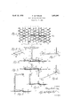
- a further object is to provide sucha' clip with means whereby the workmen may H 30 readily bend or deflect the device by hand into engagement with the part to which it is to be applied and to provide such a device having certain other new and useful features, the invention consisting in such a structure embodying the several matters, all as hereinafter more fully set forth and particularly pointed out in the appended claims, reference being had to the accompanying drawings in which Figure 1 is a view illustrative of the application of the device embodying the invention,
- Fig. 2 is a transverse section through Fig. 1 substantially upon the line 2-2;
- Fig. 3 is a view similar to Fig. 2 and illustrating the manner in which the clip is applied; I
- FIG. 4 is a perspectiveview of the clip device detached;
- Fig; 5 1 s a detail illustrating the manner in which the clip device is used forsecuring metal latlr'to a channel frame member, said cl1p device being modified slightly in construction for application to such achan- -nel member;
- Fig. 6. is a view similar to Fig. 5 illustratmetal lath to an angle beam or other L-shaped metal frame member;
- Fig. 7 is a side elevationof a clip showing a slightly modified construction
- the device embodying ,thepresent invention is shown as applied in use to hold expanded metal lath to the underside ofan I-beam in floor constructions and other places where building materials of different kinds are to be secured to beams or other supporting members, particularly in a fireproof building construction.
- 1 indicates a portion *of an I-beam commonly used in constructing floors, walls and other parts of fireproof buildings where cement is applied to and covers the metal lath.
- the end of the clip, opposite that which is formed with the hook 5, is turned at right angles to the body portion 4 and then bent backwardly upon this portion, forming a projecting handle portion 7 and the end portion.
- of the wire is then bent around as atS to embrace the wire adjacent the right 7 angle bend9 and is then extended outwardly in a direction longitudinally of the body portion 4 forming anextension arm 10 which is then bent substantially at right angles as at 11 to provide an end arm or hook 12.
- the book 5 of the clip is first inserted through an Opening in the expanded metal lath 2 andengaged over the flange 6 of the I-beam.
- This end portion 12 is then brought over the opposite rlange 13 of the I-beam by the workman taking hold of the loop or handle portion 7 and bending the wire at the bend 9 until the loop portion 7 lies in the longitudinal plane of the body 4.
- This bending operation swings the end 12 over the flange 13 of the I beam and brings it into firm engagement there- 1 with, thus, drawing the metal lath firmly v againstthe base of the I-beam and securely attaching it thereto.
- the arrangement is such that the bend 9 rests against the metal lath just at the edge of the flange 13 and thus this edge portion forms a fulcrum over which the wire of the clip is bent when the loop or handle portion 7 is deflected or bent into alignment with the body portion 4.
- the metal lathis by this simple clip, thussecured to the I-beam and holds with suflicient strength to hold the lath in place until such time as the cement or like material is applied and covers both the lath and the clip or clips.
- this clip Because of the construction of this clip and themanner in which it is hooked over the part to which it is to be attached, this prevents the clip from turning when force is I applied to the loop 7 to bend the wire and I when so bent, the end portion 12 swings over the other flange or part of the member to .,which it is to be attached and firmly draws that end of the body of the clip towardthe supporting member, firmly clamping and.
- Fig. 6 the clip is shown as applied to an angle bar and in this case the body 4 of the clip is extended in length and bent intermediate its ends so that the hook 5 may engage over the upstanding flange of the angle
- Fig. 7 a modified form of clip is shown in which-both ends of the clip are made alike, that is with a right angular loop 7 and a hook portion 12. -This clip is used where the hooked end 5 could not be readily inserted and engaged with the member to which it lsto be applied and in applying this mem- ,ber the two loops and handle portions 7 are bent downward into the plane of the body 4 thus rotating the bent ends of the wire about the angle bend 9 and projecting these bent ends into engagement with the partto which ln Fig.
- This clip is for use whereever. it is more convenient and desirable to use a. doubleclipinsteadof a single clip and as the two clips are connected by the connecting portion 15 these two clip'sare held in alignment and in proper spaced relation.
- said'wrapped :a'nound portion being extended to provide a portion to engage the part to which the devicev :is to be applied and to be deflected into engagement therewith by bending the wire at :said bend by means of said lever portion.
- a clip device for the purpose described comprising a bendable member providing a body portion and bent to provide a lever portion at one end of said body portion by forming a loop extending substantially at right angles to said body, the end portion of the member beyond said lever portion being bent angularly to said body portion to engage a part to which said device is to be applied, said member between said lever portion and end portion being engaged within said angle between said body and lever portion.
- a clip device for the purpose described formed from a length of wire providing a straight body portion and bent to form a hook at one end of said body, and at the opposite end of said body, bent at substantially right angles to the body and folded upon itself to form a lever portion with the end portion of said wire wrapped about the adjacent portion of the wire at said angle and extended longitudinally of and beyond said end of said body, thence bent angularly to provide an end portion adapted to be brought into engagement with the part to which the clip is applied, by bending said wire at said angle of said lever portion.
Description
April 12, 1932. P. SATTERLEE CLIP FOH BUILDING MATERIALS Filed Feb. 7, 1929 27 csar ere INVENTOR ATTORNEYS vice which is e is building Patented Apr. 12, 1932.
PERCY SATTERLEE, OLE DETROIT,
MICHIGAN, ASSIGN OR TO. GERALD M. PRZYBYLSKI, OF
DETROIT, MICHIGAN V CLIP FOR BUILDING MATERIALS Application filed February 7, 1929. Serial No." 338,139.
This invention relates to a clip'ordevice for securing building materials to their supports or to other places of attachment and an object of the invention is to provide adecheap to manufacture and may be quickly and easily manipulated in use, without the use'of tools. A further object is to provide a clip which is especially adapted for use in io securing'expanded'metal laths and other "fireproof building materials in place in the building of fireproof structures in which Portland cement or similar materials are used. in a plastic state in constructing the and which cementitious material parts and also the clip embodying covers the the present invention.
' With the above and other ends in view, the invention consists inthe provision of a or holding device which may be readily applied to the part to be held by inserting the device and then bending or deflecting the same to engage parts thereof withthe members of the building structure to hold the 5 parts inplace thereon, the device when in place offering 110 obstruction to the application of cement in the completing of the structure. A further object is to provide sucha' clip with means whereby the workmen may H 30 readily bend or deflect the device by hand into engagement with the part to which it is to be applied and to provide such a device having certain other new and useful features, the invention consisting in such a structure embodying the several matters, all as hereinafter more fully set forth and particularly pointed out in the appended claims, reference being had to the accompanying drawings in which Figure 1 is a view illustrative of the application of the device embodying the invention,
in use and showing the clip or holding de-.
vice as applied to the attaching of expanded metal lath to a metal I-beam;
Fig. 2 is a transverse section through Fig. 1 substantially upon the line 2-2;
Fig. 3 is a view similar to Fig. 2 and illustrating the manner in which the clip is applied; I
simple in construction and -ing the use of the clip in securing expanded Fig. 4 is a perspectiveview of the clip device detached; Fig; 5 1s a detail illustrating the manner in which the clip device is used forsecuring metal latlr'to a channel frame member, said cl1p device being modified slightly in construction for application to such achan- -nel member;
Fig. 6. is a view similar to Fig. 5 illustratmetal lath to an angle beam or other L-shaped metal frame member;
Fig. 7 is a side elevationof a clip showing a slightly modified construction; and
Fig. Sis a perspective view of a modified construction of clip.
For the purposes of illustration, the device embodying ,thepresent invention is shown as applied in use to hold expanded metal lath to the underside ofan I-beam in floor constructions and other places where building materials of different kinds are to be secured to beams or other supporting members, particularly in a fireproof building construction. As illustrated in the accompanying drawings, 1 indicates a portion *of an I-beam commonly used in constructing floors, walls and other parts of fireproof buildings where cement is applied to and covers the metal lath. I
The device 3 embodying the present invention and as shown in Fig. .1,comprises a single length of wire forming a straight body portion 4: having a hooked end 5 formed thereon to engage through the metal lath 2 and hook over the edge of the flange 6 of the I-beam 1. The end of the clip, opposite that which is formed with the hook 5, is turned at right angles to the body portion 4 and then bent backwardly upon this portion, forming a projecting handle portion 7 and the end portion. of the wire is then bent around as atS to embrace the wire adjacent the right 7 angle bend9 and is then extended outwardly in a direction longitudinally of the body portion 4 forming anextension arm 10 which is then bent substantially at right angles as at 11 to provide an end arm or hook 12.
In applying the clip 3', as illustratedin Fig. 3,the book 5 of the clip is first inserted through an Opening in the expanded metal lath 2 andengaged over the flange 6 of the I-beam. The body 4 of the chip is then brought against the underside o' the lath and the straight end portion 12 which extends at right angles to the body4= is inserted through an opening in the lath. This end portion 12 is then brought over the opposite rlange 13 of the I-beam by the workman taking hold of the loop or handle portion 7 and bending the wire at the bend 9 until the loop portion 7 lies in the longitudinal plane of the body 4. This bending operation swings the end 12 over the flange 13 of the I beam and brings it into firm engagement there- 1 with, thus, drawing the metal lath firmly v againstthe base of the I-beam and securely attaching it thereto.
The arrangement is such that the bend 9 rests against the metal lath just at the edge of the flange 13 and thus this edge portion forms a fulcrum over which the wire of the clip is bent when the loop or handle portion 7 is deflected or bent into alignment with the body portion 4. The metal lathis, by this simple clip, thussecured to the I-beam and holds with suflicient strength to hold the lath in place until such time as the cement or like material is applied and covers both the lath and the clip or clips. Because of the construction of this clip and themanner in which it is hooked over the part to which it is to be attached, this prevents the clip from turning when force is I applied to the loop 7 to bend the wire and I when so bent, the end portion 12 swings over the other flange or part of the member to .,which it is to be attached and firmly draws that end of the body of the clip towardthe supporting member, firmly clamping and.
holding the metal lath therebetween.
With this construction of clip it is unnecessary to make the body it of the clip of an exact length to correspond with the width of the base of the I-beam because should this body portion of the clip be longer than the width of the base, said clip may be-placed at an angle across the base, as shown in dotted lines in Fig. 1, and the metal lath will hold 1 it in this angular position due to the engagethe securing of metal lathto a channel mem-i her and in this case the body of the clip is;
lengthened sufiiciently to extend across the top side of the channel with the hooked end the clip is to be applied.
portion 5 engaging the edge of the upper flange of the channel.
In Fig. 6 the clip is shown as applied to an angle bar and in this case the body 4 of the clip is extended in length and bent intermediate its ends so that the hook 5 may engage over the upstanding flange of the angle In Fig. 7 a modified form of clip is shown in which-both ends of the clip are made alike, that is with a right angular loop 7 and a hook portion 12. -This clip is used where the hooked end 5 could not be readily inserted and engaged with the member to which it lsto be applied and in applying this mem- ,ber the two loops and handle portions 7 are bent downward into the plane of the body 4 thus rotating the bent ends of the wire about the angle bend 9 and projecting these bent ends into engagement with the partto which ln Fig. 8 a further modified construction ls shown wherein it is made from a single length of wire to provide a double clip, the intermediate 'or body portion of the wire being formed intermediate its ends with a hook portion 14 at the end of each body portion 4 with the ends of the hooks connected by a transverse run 15 of the wire. Thecnds.
of the wire are formed into handle and hook end portions the sameas in the construction shown in Fig. 4. This clip is for use whereever. it is more convenient and desirable to use a. doubleclipinsteadof a single clip and as the two clips are connected by the connecting portion 15 these two clip'sare held in alignment and in proper spaced relation.
Obviously changes maybe made in the particular way in which the clip' embodying this invention is formed,'the essential featuresof the present clip being hooked and the opposite end portion provided with a bent end forming a hook and a lever portion by means of which this bent end may be bent into engagement with'the part to which the clip is applied. Changes are contemplated in the particular construction within the scope of the appended claims and I do not therefore limit myself to the particular constructions shown.
Having hus fully described my invention, what I claim is 1. A device of the character described .formed of wire with a body portion and thewire bent adjacent one end of said body portion to form a lever portion extending .at an angle to said body with the .end portion of the wire wrapped around said lever portion adjacent the meeting-angle of said lever".
portion and body, and said'wrapped :a'nound portion being extended to provide a portion to engage the part to which the devicev :is to be applied and to be deflected into engagement therewith by bending the wire at :said bend by means of said lever portion.
2. A clip device for the purpose described comprising a bendable member providing a body portion and bent to provide a lever portion at one end of said body portion by forming a loop extending substantially at right angles to said body, the end portion of the member beyond said lever portion being bent angularly to said body portion to engage a part to which said device is to be applied, said member between said lever portion and end portion being engaged within said angle between said body and lever portion.
3. A clip device for the purpose described formed from a length of wire providing a straight body portion and bent to form a hook at one end of said body, and at the opposite end of said body, bent at substantially right angles to the body and folded upon itself to form a lever portion with the end portion of said wire wrapped about the adjacent portion of the wire at said angle and extended longitudinally of and beyond said end of said body, thence bent angularly to provide an end portion adapted to be brought into engagement with the part to which the clip is applied, by bending said wire at said angle of said lever portion.
In testimony whereof I aflix my signature.
PERCY SATTERLEE.
Priority Applications (1)
| Application Number | Priority Date | Filing Date | Title |
|---|---|---|---|
| US338139A US1853380A (en) | 1929-02-07 | 1929-02-07 | Clip for building materials |
Applications Claiming Priority (1)
| Application Number | Priority Date | Filing Date | Title |
|---|---|---|---|
| US338139A US1853380A (en) | 1929-02-07 | 1929-02-07 | Clip for building materials |
Publications (1)
| Publication Number | Publication Date |
|---|---|
| US1853380A true US1853380A (en) | 1932-04-12 |
Family
ID=23323559
Family Applications (1)
| Application Number | Title | Priority Date | Filing Date |
|---|---|---|---|
| US338139A Expired - Lifetime US1853380A (en) | 1929-02-07 | 1929-02-07 | Clip for building materials |
Country Status (1)
| Country | Link |
|---|---|
| US (1) | US1853380A (en) |
-
1929
- 1929-02-07 US US338139A patent/US1853380A/en not_active Expired - Lifetime
Similar Documents
| Publication | Publication Date | Title |
|---|---|---|
| US1562784A (en) | Anchor strip for securing finishing structures to concrete | |
| US1373036A (en) | Wall-board fastener | |
| US1853380A (en) | Clip for building materials | |
| US2467558A (en) | Nail receiving metallic floor beam | |
| US1610082A (en) | Fastener | |
| US2697262A (en) | Panel clip | |
| US1962452A (en) | Tying clip for metal lath | |
| US1484524A (en) | Metal-lath clip | |
| US1955247A (en) | Means for mounting lathing material | |
| USRE10684E (en) | Fastening wire lathing to iron frames of buildings | |
| US560605A (en) | Corner plaster-supporting strip or lath | |
| US1764772A (en) | Anchor insert for concrete work | |
| US297862A (en) | For coeeugated metal sheets | |
| US2216019A (en) | Plaster lath clip | |
| US1703560A (en) | Lath-spacing nail | |
| US1073082A (en) | Metallic clip-fastening. | |
| US1675201A (en) | Wire-lath bracket | |
| US1800670A (en) | Plaster-board structure and clip therefor | |
| US1357018A (en) | Plaster gage and reinforcement | |
| US1372387A (en) | Lathing | |
| US2674914A (en) | Corner fastener | |
| US1546522A (en) | Wall construction | |
| US1838120A (en) | Building structure | |
| US1854645A (en) | Clip for engaging wall board to supporting elements | |
| US1918256A (en) | Metal furring strip |