US185337A - Improvement in ditching-machines - Google Patents
Improvement in ditching-machines Download PDFInfo
- Publication number
- US185337A US185337A US185337DA US185337A US 185337 A US185337 A US 185337A US 185337D A US185337D A US 185337DA US 185337 A US185337 A US 185337A
- Authority
- US
- United States
- Prior art keywords
- plow
- attached
- chain
- ditcher
- ditch
- Prior art date
- Legal status (The legal status is an assumption and is not a legal conclusion. Google has not performed a legal analysis and makes no representation as to the accuracy of the status listed.)
- Expired - Lifetime
Links
- 238000010276 construction Methods 0.000 description 2
- XEEYBQQBJWHFJM-UHFFFAOYSA-N iron Substances [Fe] XEEYBQQBJWHFJM-UHFFFAOYSA-N 0.000 description 1
- 229910052742 iron Inorganic materials 0.000 description 1
- 230000002040 relaxant effect Effects 0.000 description 1
- 230000000284 resting effect Effects 0.000 description 1
Images
Classifications
-
- E—FIXED CONSTRUCTIONS
- E02—HYDRAULIC ENGINEERING; FOUNDATIONS; SOIL SHIFTING
- E02F—DREDGING; SOIL-SHIFTING
- E02F7/00—Equipment for conveying or separating excavated material
Definitions
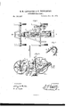
- FIG. 1 is a plan view of our ditchingmachine.
- FIG. 2 is a longitudinal section of the same on the line or w of Fig. 1.
- Fig. 3 shows a part of the elevator.
- D is the beam of the ditcher, which is not attached to the wagon except by the draft-chain a, hooked to a clevis, b, at the front end of the beam.
- This clevis has a series of holes, as shown, so that the chain can be hooked high or low, as desired, the chain passing from the clevis around a pulley, d, under the front axle G, and up to a Windlass, G, arranged in the frame A under the front seat E.
- the beam is further suspended by a cord or chain, e,running upward to another Windlass, G, in the wagon-frame A, which elevates the plow or ditcher and carries it when not ditchmg.
- the two windlasses G G are provided, respectively, with the operating-levers H H: and suitable pawls and ratchets for turning the same and holding them in place.
- I is the plow attached to the rear part of the beam D,and J isthe elevator belt orapron, The pulley f in the plow, around which the elevators run, is not attached to the plow, therefore the plow or ditcher will play up and down free, any depth or height desired; and,
- the stays K may be of sufficient length to suit any depth of ditch.
- ' P is an upright perforated bar, resting on a spring, m, attached to the top of the beam, and
- the spring m is put in use by said bar I? and lever B to cause the plow or ditcher to run steady.
- This upright bar with holes is to be of sufficient length to follow the plow or ditcher down any depth desired, by hitching the lever upon it every cut or round.
- 19 is the coupling-rod, running through the front axle, and is held in position by a temperscrew, n, in the cross-piece above the axle.
- a temperscrew, n On the lower end of this rod the pulley d is attached for the draft-chain a to run around; and a rod or chain, 1', is also connected to the lower end of said coupling-rod, and runs forward, hooking on or near the hammer in the tongue.
- This rod or chain is to be hooked back and lengthened each cut or round, in order that the draft-chain may be lowered at the hitching-point as the ditcherlowers in the ditch.
- the elevator-belt is a small buckle-chain, 8, attached to the belt, which chain runs over small cogs t on a-pulley, S,
- each edge of the belt On each edge of the belt are vertical sides or edges 1;,forming a trough to hold'dirt and keep it from falling off. These edges or sides are made in short joints of sheet-iron, and attached to the belt by cross-bars and elevators traveling with the belt, the joints lapping each other.
- the elevators w to consist simply of cross-bars of suitable depth, as the belt is extended back of the wagon and does not run steep.
- the earth elevated-by the elevators passes over the pulley S and falls'on the slide T, conducting the dirt close to the side of the ditch, the dirt falling on one side of the ditch, passing one way, and, while passingthe other way,
- a cog-wheel, V which meshes with another wheel, 'W, on a shaft, X.
- a pulley, Y On this shaft is a pulley, Y, from which a chain or belt, 00, runs to a pulley, g, on the same shaft as the elevator-pulley S.
- the shaft X has its outer bearing in a lever, Z, by means of which it can be moved so as to throw the cog-wheel W out of gear with the wheel V, and thus stop the elevator.
- the ditching-plow I provided with the sides I, constructed as described, in combination with the elevator J, haviugits lower pul- -ley f placed loosely Within the plow to allow the elevator to adjust itself to the movement of the plow, substantially as and for the purposes herein set forth.
Landscapes
- Engineering & Computer Science (AREA)
- Mining & Mineral Resources (AREA)
- Civil Engineering (AREA)
- General Engineering & Computer Science (AREA)
- Structural Engineering (AREA)
- Soil Working Implements (AREA)
- Sewage (AREA)
Description
ELIAS H. LANCASTER AND HIRAM TEWKSBURY, OF MONTPELIER, INDIANA.
IMPROVEMENT IN DlTCHlNG-MACHINES.
Specification forming part of Letters Patent No. 185.337, dated December 12, 1876 application filed August 29, 1876.
To all whom it may concern:
Be it known that we, ELIAS H. LANCASTER and HIRAM TEWKSBURY, of Montpelier, in the county of Blackforcl and in the State of Indiana, have invented certain new and useful Improvements in Ditching-Machines; and do hereby declare that the following is a full, clear, and exact description thereof, reference being had to the accompanying drawings and to the letters of reference marked thereon, making a part of this specification.
The nature of our invention consists in the construction and arrangement of a ditchingmachine, as will be hereinafter more fully set forth.
In order to enable others skilled in the art to which our invention appertains to make and use the same, we will now proceed to describe its construction and operation, referring to the annexed drawing, in which Figure 1 is a plan view of our ditchingmachine. 'Fig. 2 is a longitudinal section of the same on the line or w of Fig. 1. Fig. 3 shows a part of the elevator.
Arepresents asuitable frame-work attached to the rear axle B and coupled to the front axle O, forming the wagon, under which the ditcher runs. D is the beam of the ditcher, which is not attached to the wagon except by the draft-chain a, hooked to a clevis, b, at the front end of the beam. This clevis has a series of holes, as shown, so that the chain can be hooked high or low, as desired, the chain passing from the clevis around a pulley, d, under the front axle G, and up to a Windlass, G, arranged in the frame A under the front seat E. The beam is further suspended by a cord or chain, e,running upward to another Windlass, G, in the wagon-frame A, which elevates the plow or ditcher and carries it when not ditchmg.
The two windlasses G G are provided, respectively, with the operating-levers H H: and suitable pawls and ratchets for turning the same and holding them in place.
I is the plow attached to the rear part of the beam D,and J isthe elevator belt orapron, The pulley f in the plow, around which the elevators run, is not attached to the plow, therefore the plow or ditcher will play up and down free, any depth or height desired; and,
as the plow or ditcher passes down in the ditch, it is caused to fall back each round by relaxing the draft-chain in front, in order that the elevators may keep their proper positions in the plow when the ditcher is down in the ditch.
Attached to the beam D near the ends are four upright stays, K, which extend up between braced stays L attached to the frame or wagon A,steadying the ditcher. The stays K may be of sufficient length to suit any depth of ditch.
Under the beam D is pivoted a bar, M, carrying the roller N, and this bar is, by a toggle joint, h it, connected withan uprightlever, 0, having a pin, 6, through its lower end, which works under staples 7c fastened on the top of the beam D. This upright lever O is used to raise or lower the wheel or roller N which governs the depth of theplow. When the lever is perpendicular the plow is out and, by the use of this lever, the plow may be thrown out or in instantaneously, giving any depth de sired, in order to level the ditch to suit the team.
' P is an upright perforated bar, resting on a spring, m, attached to the top of the beam, and
runs up through and is fastened to a lever, 1%,
attached to the wagon. The spring m is put in use by said bar I? and lever B to cause the plow or ditcher to run steady. This upright bar with holes is to be of sufficient length to follow the plow or ditcher down any depth desired, by hitching the lever upon it every cut or round.
19 is the coupling-rod, running through the front axle, and is held in position by a temperscrew, n, in the cross-piece above the axle. On the lower end of this rod the pulley d is attached for the draft-chain a to run around; and a rod or chain, 1', is also connected to the lower end of said coupling-rod, and runs forward, hooking on or near the hammer in the tongue. This rod or chain is to be hooked back and lengthened each cut or round, in order that the draft-chain may be lowered at the hitching-point as the ditcherlowers in the ditch.
Underneath the elevator-belt is a small buckle-chain, 8, attached to the belt, which chain runs over small cogs t on a-pulley, S,
whereby the elevator-belt may run slack, and,
yet not slip on said pulley. On each edge of the belt are vertical sides or edges 1;,forming a trough to hold'dirt and keep it from falling off. These edges or sides are made in short joints of sheet-iron, and attached to the belt by cross-bars and elevators traveling with the belt, the joints lapping each other. The elevators w to consist simply of cross-bars of suitable depth, as the belt is extended back of the wagon and does not run steep.
The earth elevated-by the elevators passes over the pulley S and falls'on the slide T, conducting the dirt close to the side of the ditch, the dirt falling on one side of the ditch, passing one way, and, while passingthe other way,
it falls on the other side of the ditch.
Attached to the hub of one of the wagonwheels is a cog-wheel, V, which meshes with another wheel, 'W, on a shaft, X. On this shaft is a pulley, Y, from which a chain or belt, 00, runs to a pulley, g, on the same shaft as the elevator-pulley S.
The shaft X has its outer bearing in a lever, Z, by means of which it can be moved so as to throw the cog-wheel W out of gear with the wheel V, and thus stop the elevator.
To the sides of the beam D in front of the plow I are attached cutters A for cutting the sides of the ditch. The plow is provided with sides I, which run up and are attached to the beam back of the lower-end pulley of the elevator, and prevent any earth or mud from choking the sides of the ditch, helping the earth on the elevator. The cutters and plow being the widest, allows of the ditch being cut on a circle. To cut a square turn, the ditcher must be elevated out of the ditch and turned and let down again.
Having thus fully described our invention, what We claim as new, and desire to secure by Letters Patent, is-
1. The combination, with a wagon, A, of the ditcher-beam D, with its front end supported by the adjustable roller N, draft-chain beam D, the upright stays K K attached thereto, and the stays L L attached to the wagonframe, substantially as and for the purposes herein set forth.
4. The combination of the ditcher-beam D, bar M, roller N, toggle-joint h h, lever O, with pin 1: and staple is, substantially as and for the purposes herein set forth.
5. The combination, with the wagon-frame A and front axle O, of the coupling-rod 1), setscrew n, draft-chain pulley d, and rod or chain 1', as and for the purposes herein set forth.
6. The ditching-plow I, provided with the sides I, constructed as described, in combination with the elevator J, haviugits lower pul- -ley f placed loosely Within the plow to allow the elevator to adjust itself to the movement of the plow, substantially as and for the purposes herein set forth.
In testimony that we claim the foregoing we have hereunto set our hands this 10th day of July, 1876.
ELIAS H. LANCASTER. HIRAM TEWKSBURY.
Witnesses:
R. G. SWANN, G. H. BENNETT.
Publications (1)
| Publication Number | Publication Date |
|---|---|
| US185337A true US185337A (en) | 1876-12-12 |
Family
ID=2254743
Family Applications (1)
| Application Number | Title | Priority Date | Filing Date |
|---|---|---|---|
| US185337D Expired - Lifetime US185337A (en) | Improvement in ditching-machines |
Country Status (1)
| Country | Link |
|---|---|
| US (1) | US185337A (en) |
-
0
- US US185337D patent/US185337A/en not_active Expired - Lifetime
Similar Documents
| Publication | Publication Date | Title |
|---|---|---|
| US947964A (en) | Hay or manure loading machine. | |
| US185337A (en) | Improvement in ditching-machines | |
| US351930A (en) | Ditching-machine | |
| US379745A (en) | Potato-drill | |
| US213897A (en) | Improvement in ditching-machines | |
| US108176A (en) | Improvement in combined plows and scrapers for roads | |
| US30884A (en) | Improvement in steam-plows | |
| US292355A (en) | Ditching-machine | |
| US294567A (en) | Ditching-machine | |
| US96724A (en) | Improved excavator | |
| US304620A (en) | Ditching-machine | |
| US316846A (en) | William h | |
| US1202947A (en) | Traction-plow. | |
| US295451A (en) | Excavator | |
| US510628A (en) | Hay-ricker | |
| US849079A (en) | Road-grader. | |
| US168967A (en) | Improvement in ditching-machines | |
| US7723A (en) | Machine for excavating- and conveying earth | |
| US317279A (en) | Wheeled scraper | |
| US156139A (en) | Improvement in ditching-plows | |
| US491577A (en) | Excavator | |
| US354136A (en) | Ditching and grading machine | |
| US308783A (en) | Capstan for stump-extractors | |
| US150767A (en) | Improvement in excavators | |
| US378406A (en) | Oeading and ditching machine |