US1853377A - Looping machine - Google Patents
Looping machine Download PDFInfo
- Publication number
- US1853377A US1853377A US444589A US44458930A US1853377A US 1853377 A US1853377 A US 1853377A US 444589 A US444589 A US 444589A US 44458930 A US44458930 A US 44458930A US 1853377 A US1853377 A US 1853377A
- Authority
- US
- United States
- Prior art keywords
- chain
- articles
- stitches
- severing
- blade
- Prior art date
- Legal status (The legal status is an assumption and is not a legal conclusion. Google has not performed a legal analysis and makes no representation as to the accuracy of the status listed.)
- Expired - Lifetime
Links
- 239000004744 fabric Substances 0.000 description 48
- 230000007246 mechanism Effects 0.000 description 46
- 230000003028 elevating effect Effects 0.000 description 23
- 238000009958 sewing Methods 0.000 description 7
- 238000010276 construction Methods 0.000 description 5
- 239000011435 rock Substances 0.000 description 2
- 238000009966 trimming Methods 0.000 description 2
- 101100006982 Mus musculus Ppcdc gene Proteins 0.000 description 1
- 241000287181 Sturnus vulgaris Species 0.000 description 1
- 230000007547 defect Effects 0.000 description 1
- 230000000694 effects Effects 0.000 description 1
- 238000007689 inspection Methods 0.000 description 1
- 230000010355 oscillation Effects 0.000 description 1
- 239000004753 textile Substances 0.000 description 1
Images

Classifications
-
- D—TEXTILES; PAPER
- D05—SEWING; EMBROIDERING; TUFTING
- D05B—SEWING
- D05B7/00—Linking machines, e.g. for joining knitted fabrics
-
- Y—GENERAL TAGGING OF NEW TECHNOLOGICAL DEVELOPMENTS; GENERAL TAGGING OF CROSS-SECTIONAL TECHNOLOGIES SPANNING OVER SEVERAL SECTIONS OF THE IPC; TECHNICAL SUBJECTS COVERED BY FORMER USPC CROSS-REFERENCE ART COLLECTIONS [XRACs] AND DIGESTS
- Y10—TECHNICAL SUBJECTS COVERED BY FORMER USPC
- Y10S—TECHNICAL SUBJECTS COVERED BY FORMER USPC CROSS-REFERENCE ART COLLECTIONS [XRACs] AND DIGESTS
- Y10S112/00—Sewing
- Y10S112/01—Suction thread cutting
Definitions
- machines of this character generally include a continuously rotating dial provided with impaling pins arranged thereon upon which the fabrics, such as stockings, are impaled, the dial rotating past a stitch-forming mechanism which sews the edges of the fabric together and which produces a chain of stitches between adjacent fabrics.
- mechanism is provided which operates on the chain to cause the same to curl up so as posi-. tively to insure engagement of the chainby a chain-ii ter which, in turn, presents the thread to the severing mechanism.
- the chain curling device of my said patent is not always satisfactory in operation because it does not positively raise the chain so that it may be engaged by the chain-lifter. Furthermore, in my prior patent the chainlifter is so mounted that it is retarded in its oscillation by contact with the welt or looping seam and this has resulted in a marking of the fabric, especially where the fabric is of the light chiffon type.
- My present invention aims primarily to provide in a looping machine having a chain severing attachment means for positively elevating the chain into the zone of operation of the severing mechanism.
- a further object of the invention is to pro-- vide in combination with a. chain elevating device a mechanism which operates in opposition to the elevating device whereby to insure that the fabric is maintained properly on the impaling pins.
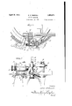
- FIG. 1 is a plan view of a portion of a looping machine showing the attachment of my invention mounted thereon
- Fig. 2 is afront elevation of the attachment illustrated in Fig.1 I
- Fig. 3 is a view in horizontal section, parts being broken away for the sake of clearness;
- Fig. 4- is a View, partly in elevation and partly in section, showing the details of my invention and the several parts in operative relation;
- Fig. 5 is a perspective view of a chain guide forming a part of my invention.
- the fabric articles such as stockings, which anism for severing the chain of stitches between adjacent fabric articles.
- the severing mechanism comprises a pair of relatively 'movable'she'aring blades 3 and 4, the blade 3 being stationary and adjustably I mounted on a suitable bracket 5 which forms an extension on a bracket 6 by means of which the attachment, as a unit, may be mounted on the frame of the machine;
- the bracket 5 terminates in a transversely extending tubular housing 7 in which is ournale'd a rock shaft 8 upon which the movable blade 4 is mounted.
- the movable blade 4 is provided with an extension 9 which is connected toan adjustable link 10 which, in turn, is connected to an eccentric'll operated by a worm- 12.
- the worm 12 receives its motion from the looping machine.
- a chain-lifter14 Gperatively connected to the movable blade 4 is a chain-lifter14 which is maintained in "assembled relation with the movable blade by a suitable adjusting nut 15. a a
- a suitable coil spring 16 is securedto the 'brackete and the chain-lifter 14', this spring assisting the movement of the chain-lifter and the movable blade 4' on the return stroke towa'rdthje stationary blade 3.
- the particular improvement of my presfcollar ent invention resides in the provision of a chain elevating device which will positively raise the chain so as to insure its engagement by the chain-lifter by which it is presented to the severing mechanism.
- This means comprises a blade 1? which is pivotally mounted on a post 18 to swing in ahorizontal plane close to the impaling pins 2.
- the bearing for the blade 17 is provided with a suitable coil spring 19 which constantly urges the blade forward into engagement with the chain of stitches.
- the blade is provided with a beveled nose 20 which bears against the chain of stitches as the fabric articles on the impaling pins pass by the elevating device.
- Suitable adjusting mechanisms areprovided for accurately positioning the blade 17 with respect to the work. For this purpose the blade isadjustable horizontally by a slot and pin 'conneceon-'21 and the pivot post 18 is maintained in proper vertical position by suitable set screws 22 and 23.
- the blade 17 bears constantly against the chain of stitches on the fabric articles by reason of the force of the spring- 19.
- This action of the blade has a tendency to move the articles outwardon the impa'ling pins.
- the member 24 is provided with a collar 25 rotatably mounted on a post 26.
- a suitable coil ,spring27 is secured to the post and'the collar and is so mounted that it tends constantly to urge'jthe member 24 into engagement with the fabric articles.
- a pin 28 on the post 26 operatesv in a slot 29 in the movement of the "member 24.
- the post 26 may be accurately 'sition by suitable set screws 30 and 31.
- the blade 1-? and for the purpose of limiting swinging the member 24 operate in opposition to each other on the fabric articles, each being urged into contact with the articles by means of a suitable spring.
- the post 36 is maintained in adjusted position by suitable set screws 38 and 39.
- This guide plate presses down upon the chain and thus also performs the function of removing from it any loose threads or clippings which may have been left after the trimming operation.
- the chain is positively raised by the device described and is therefore readily engaged by the chain-lifter 14 which constantly oscillates freely above the plane of the chain.
- the lifter 1d carries the chain into the zone of operation of the cutter blades 3 and l where the chain is severed;
- suitable guide 40 may beinterposed between the blade 17 and the chain lifter 14 further to assist in the accurate presentation of the chain to pins.
- a suitable stop a1 is provided which prevents vertical movement ofthe blade.
- mechanism for severingthe chain between adjacent articles means oscillative in a non-vertical plane and operative to elevate said chain prior to its introduction to the severing mechanism, said means being maintained in inoperative position by the articles, and means urging said elevating means into operative position.
- mechanism for, severing the chain between adjacent articles and spring-actuated means oscillative in a non-vertical plane and adapted to move under said chain to elevate the same prior to its introduction to the severing mechanism, said means being restrained against movement by the articles.
- a machine for sewing looped fabrics including a movable support, impaling pins for receiving fabric articles mountedon said support and movable therewith, stitch forming mechanism for uniting said articles by forming achain of stitches, mechanism for severing the chain between adjacent articles, and means oscillative in, a non-vertical plane and controlled by the articles for elevating said chain prior to its introduction to said severing mechanism.
- a machine for sewing looped fabrics including a movable support, impaling pins for receiving fabric articles mounted on said support and movable therewith, stitch-forming mechanism for uniting said articles by forming a chain of stitches, mechanism for severing the chain between adjacent articles, and meansoscillative in a non-vertical plane for elevating said chain prior to its introduction to the severing mechanism, said means being restrained against movement by the articles.
- a machine for sewing looped fabrics including a movable support, impalingpins for receivingfabric articles mounted on said support and movable therewith, stitch-forming mechanism for uniting said articles by forming a chain of stitches,.mechanism for severing the chain between adjacent articles, means oscillative in a non-vertical plane and adapted to moveunder said chain to elevate the same prior'to its introduction to said severing mechanism, and means-to restrain movement of said first-mentioned means.
- a machine'for sewing looped fabrics including a movable support provided with radially projecting impaling pins adapted to receive fabric articles and stitch-forming mechanism for uniting the edges of said articles by a chain of stitches, a chain elevating deviceoscillative in a non-vertical plane and bearing against said chain, and means operating in opposition to said elevating device to maintain the articles properly positioned on the impaling pins.
- amachine for sewing looped fabrics including a movable support provided with impaling pins for receivingfabric articlesand stitch-forming mechanism foruniting the edges of said articles by a chain of stitches, a spring-actuated chain elevating device bearing against said chain, and spring means operating in opposition to said elevating device to-maintain the articles properly positioned on the impaling pins.
- a machine for sewing looped fabrlcs including a movable support provided with radially projecting impaling pins adapted to receive fabric articles and stitchformingmechanism for uniting the edges of said articles by a chain of'stitches, a chain elevating device oscillative in a non-vertical plane and bearing against said chain in a plane above the impaling pins, and means operating in a plane below said impaling pins and in opposition to said elevating device to maintain the articles properly positioned on the impaling pins.
- a machine for sewing looped fabrics including a movable support provided with impaling pins for receiving fabric articles and stitch-forming mechanism for uniting the, edges of said articles by a chain of stitches, a chain elevating device oscillative in a non-vertical plane and bearing against said chain and adapted to move underthe portion of the chain which extends between adjacent articles, and means to compress the chain prior to its engagement by said elevating device.
- mechanism for severing the chain between adjacent articles means coac tive with said mechanism for introducing said chain to said severing mechanism, said means operating continuously above the looped seam, and means oscillative in a non-vertical plane and controlled by the articles for elevating said chain prior to its introduction by said first mentioned means to the severing mechanism.
Landscapes
- Engineering & Computer Science (AREA)
- Textile Engineering (AREA)
- Treatment Of Fiber Materials (AREA)
Description
April 1932- E. E. RANDALL 1,853,377
LOOPING MACHINE Filed April 15, 1930 2 Sheets-Sheet 1 09150 5 away/4 p 2, 1932. E. E. RANDALL 1,853,377
LOOPING MACHINE Filed April 15, 1930 2 Sheets-Sheet 2 gmentoa 0930 E Panda/L ww m Patented Apr. 12, 1932 warren stares rarest critics unison n. aArrnnLL, or KANKAKEE, rnmnors, nssrenon rorannmonnr' TEXTILE mncnrnnnr 00., or onrceeo, rumors, A con-renames on rumors roornve MACHINE Application filed April 15,-
insure accurate and infallible cutting of the chain bet-ween adjacent fabrics looped on the machine.
As is well understood, machines of this character generally include a continuously rotating dial provided with impaling pins arranged thereon upon which the fabrics, such as stockings, are impaled, the dial rotating past a stitch-forming mechanism which sews the edges of the fabric together and which produces a chain of stitches between adjacent fabrics. In my said patent, mechanism is provided which operates on the chain to cause the same to curl up so as posi-. tively to insure engagement of the chainby a chain-ii ter which, in turn, presents the thread to the severing mechanism.
The chain curling device of my said patent is not always satisfactory in operation because it does not positively raise the chain so that it may be engaged by the chain-lifter. Furthermore, in my prior patent the chainlifter is so mounted that it is retarded in its oscillation by contact with the welt or looping seam and this has resulted in a marking of the fabric, especially where the fabric is of the light chiffon type.
My present invention aims primarily to provide in a looping machine having a chain severing attachment means for positively elevating the chain into the zone of operation of the severing mechanism.
It is a further object of my invention to provide a chain elevating, device which is maintained normally in inoperative position by the fabric on the impaling pins as that fabric passes the elevating device and which becomes opera-two when the chain between 1930. Serial no. 444,589.
adjacent fabrics comes into, alinement with the device.-
It is still another object of provide in a machine of the character set forth a chain-lifter which normally oscillates freely above the plane of the impalingpins and to whichthe chain is elevated by means controlled by the fabric being united.
A further object of the invention is to pro-- vide in combination with a. chain elevating device a mechanism which operates in opposition to the elevating device whereby to insure that the fabric is maintained properly on the impaling pins.
Other objects of my invention, and the many advantages thereof will in part be obvious and in part more fully brought out as the description proceeds.
" In the" accompanying drawings, I have illustrated a practical embodiment of my invention; but it is to be understood that the drawings are illustrative, merely, and that the invention is not limited to the details of construction therein disclosed. It will. be
readily apparent to those skilled in the art that the invention may be embodied in a wide variety of forms without departing from its salient features or sacrificing any of its advantages.
In these drawings: U v a Fig. 1 is a plan view of a portion of a looping machine showing the attachment of my invention mounted thereon Fig. 2 is afront elevation of the attachment illustrated in Fig.1 I
Fig. 3 is a view in horizontal section, parts being broken away for the sake of clearness;
Fig. 4- is a View, partly in elevation and partly in section, showing the details of my invention and the several parts in operative relation; and
Fig. 5 is a perspective view of a chain guide forming a part of my invention.
It is deemed unnecessary for the purposes of the present specification to describe in detail the construction and operation of a looping machine, inasmuch as the machine, itself, is old and well known in the art It will suffice to state that the machine comprises a rotatable dial 1 about the periphery of which the invention to is mounted a continuous series of impaling pins 2, which pro ect radially from the dlal.
. The fabric articles, such as stockings, which anism for severing the chain of stitches between adjacent fabric articles. The severing mechanism, proper, comprises a pair of relatively 'movable'she'aring blades 3 and 4, the blade 3 being stationary and adjustably I mounted on a suitable bracket 5 which forms an extension on a bracket 6 by means of which the attachment, as a unit, may be mounted on the frame of the machine;
The bracket 5 terminates in a transversely extending tubular housing 7 in which is ournale'd a rock shaft 8 upon which the movable blade 4 is mounted. The movable blade 4 is provided with an extension 9 which is connected toan adjustable link 10 which, in turn, is connected to an eccentric'll operated by a worm- 12. The worm 12 receives its motion from the looping machine. By this arrange ment the movable blade 4 is constantly oscillated and periodically brought into proper relation with the stationary blade 3 to cut the chain.
Gperatively connected to the movable blade 4 is a chain-lifter14 which is maintained in "assembled relation with the movable blade by a suitable adjusting nut 15. a a
As will be noted from an inspection of Figs. 2 and 4, the chain-lifter 14 swings constantly in a plane above the chain of stitches on "the machine and in this respeet. it differs from the construction disclosed in my earlier patent wherein the chain-lifter'contacts with the chain and is retarded thereby. I
A suitable coil spring 16 is securedto the 'brackete and the chain-lifter 14', this spring assisting the movement of the chain-lifter and the movable blade 4' on the return stroke towa'rdthje stationary blade 3. a b
It will be understood from .the foregoing description that the movable blade and the chain lifter are mounted together on the rock shaft 8 and are'moved in unison toward and away from the stationary blade 3. :Since the chain-lifter 14 oscillates freely abovethe plane of the impaling pins, the chain-{lifter would not en gage the chain unless some means were provided'fo'r elevating the chain above the plane of the pins. 7 a
The particular improvement of my presfcollar ent invention resides in the provision of a chain elevating device which will positively raise the chain so as to insure its engagement by the chain-lifter by which it is presented to the severing mechanism. This means comprises a blade 1? which is pivotally mounted on a post 18 to swing in ahorizontal plane close to the impaling pins 2. The bearing for the blade 17 is provided with a suitable coil spring 19 which constantly urges the blade forward into engagement with the chain of stitches. The blade is provided with a beveled nose 20 which bears against the chain of stitches as the fabric articles on the impaling pins pass by the elevating device. Suitable adjusting mechanisms areprovided for accurately positioning the blade 17 with respect to the work. For this purpose the blade isadjustable horizontally by a slot and pin 'conneceon-'21 and the pivot post 18 is maintained in proper vertical position by suitable set screws 22 and 23.
By referring particularly to Fig. 3 the operation of the blade 17 will be quite clear; As the fabric articles rotate pastthe blade, the nose 17 engages the seam portions of the chain of stitches C by which it is main tained in retracted position against-the action of the spring 19, as shown by dotted lines in Fig. 3.' lVhen the chain of stitches between adjacent fabrics comes into alinement with the beveled nose 20, this nose enters under the chain, it-being no longer restrained in its movement by the seam in the fabricai'id consequently the spring 19 be comes effectivetc -move the blade into its forward position as shown in Fig. 3. Thus, as is more clearly shown in Fig. 4, the chain 0 is elevated by the blade 17 to a position H:
wh'ere it is positively engaged by the chainlift er 14 by which in turn it is moved into the field of action of the cutting blades.
As has been above set-forth the blade 17 bears constantly against the chain of stitches on the fabric articles by reason of the force of the spring- 19. This action of the blade has a tendency to move the articles outwardon the impa'ling pins. To overcome this tendency or the blade I have provided a member 24which bears against the fabric below the impaling pins as is clearly shown in Fig. 4. The member 24 is provided with a collar 25 rotatably mounted on a post 26. A suitable coil ,spring27 is secured to the post and'the collar and is so mounted that it tends constantly to urge'jthe member 24 into engagement with the fabric articles. A pin 28 on the post 26 operatesv in a slot 29 in the movement of the "member 24. As in the case adjusted and is maintained in adjusted pcor the post 18, the post 26 may be accurately 'sition by suitable set screws 30 and 31. Thus, it will be seen that the blade 1-? and for the purpose of limiting swinging the member 24 operate in opposition to each other on the fabric articles, each being urged into contact with the articles by means of a suitable spring. By this arrangement, it is assured that the articles remain properly positioned on the impaling pins.
I have also found that if pressure be'applied to the chain of stitches to press the chain down upon the impaling pins, the chain will be straightened and at the sametime will have a tendency to rise as it is relieved from this pressure. For this purpose I have provided a presserfoot 32 secured to a post 33 which is vertically adjustable and is maintained in adjusted position by means of a suitable set screw 34. In practice the presser foot will be so'adjusted as 'tobear. down upon the chain of stitches with a sufiicient degree of pressure to smooth the chain. As the chain leaves the presser foot, it has a tendency to rise and therefore the entry of the beveled nose under the chain is materially facilitated.
Sometimes operators in impaling the fabric articles on the pins space them so far apart that after passing through the stitch forming mechanism a relatively long chain between adjacent articles is formed, as at D,
Fig. 3. To insure-that this long chain is properly and accurately presented to the severing mechanism, I have provided a guide plate 35 adj ustably secured to a post 36 which, in turn, is adjustable in'an extension 37 of the bracket 5. The post 36 is maintained in adjusted position by suitable set screws 38 and 39. This guide plate presses down upon the chain and thus also performs the function of removing from it any loose threads or clippings which may have been left after the trimming operation.
0pcmt0n.-From the foregoing description it is believed that my invention and its mode of operation will be perfectly clear to those skilled in the art. However, it is deemed desirable to summarize the operation,
here. It is understood, of course, that the dial of the machine rotates clockwise and that the fabric articles impaled upon the impaling pins first pass through trimming mechanism and then through stitch-forming mechanism. It is after the edges of the fabric articles have been united that my invention comes into operation. The dial carrying the united fabrics first passes under the guide plate 35,
: .i which assures that the chain between adjacent fabrics will be properly presented to the severing mechanism. The chain thereupon passes under the presser foot 32 which has the effect of compressing the chain and straightening it and also causing it to rise slightly as itleaves the presser foot. At this time the blade 17 is maintained in inoperative position by reason of the fact that the nose 2O bears against the chain of stitches on the fabric. articles.
As that portion of the chain which extends betweenadjacent articles comes into alinement with the beveled nose 20, the chain'rises thereon and the nose 20' enters underfthe chain, being movedby actionof the spring 19. Thus, the chain is positively raised by the device described and is therefore readily engaged by the chain-lifter 14 which constantly oscillates freely above the plane of the chain. The lifter 1d carries the chain into the zone of operation of the cutter blades 3 and l where the chain is severed; A. suitable guide 40 may beinterposed between the blade 17 and the chain lifter 14 further to assist in the accurate presentation of the chain to pins. In order to prevent lifting of the blade 17 inthe event that the chain should get under the same, a suitable stop a1 is provided which prevents vertical movement ofthe blade.
' Thus, in mypresent improvement I have I .overcome certain defects in prior devices of this character and have provided an accurate, positive means for presenting thechain to the severing mechanism. In the present case the chain lifter oscillatesfreely above the plane 1 of the pins and does not contact with the welt as in my prior construction and, therefore,"
there. is no marking of the, fabric. Furthermore, in my present invention the chain is positively raised so that it is engaged by the chain lifter andthe operation does not depend solely upon any curling action induced in the chain. 7 V
It is believed, also, that the many advantages of my present construction will be.
readilyappreciated-by those skilled in the Iclaim: 1. In a machine for uniting the edges of looped fabric articles by forming a chain of stitches, mechanism for severing the chain between adj acent articles, and means oscillative in a non-vertical plane and controlledby the articles for elevating said chain prior to its introduction to the severing mechanism.
2. In a machine for uniting the edges of looped fabric articles by forming a chain of stitches, mechanism for severing the chain between adjacent articles, and means oscillative in a non-vertical plane and adapted to.
move under said chain to elevate the same prior to its introduction to the severing mechanism, said means being restrained from movement by the articles.
3. In a machine for uniting the edges of M 5 looped fabric articles by forming a chain of looped fabric articles by forming a chain of stitches, mechanism for severing the chain between adjacent articles, and means'oscillaltive in a non-vertical plane and operative to elevate said chain prior to its introduction to the severing mechanism, said means being maintained in inoperative position by the articles I a 5. In amachine for uniting the edge'sof looped fabric articles by forming a chain of stitches, mechanism for severingthe chain between adjacent articles, means oscillative in a non-vertical plane and operative to elevate said chain prior to its introduction to the severing mechanism, said means being maintained in inoperative position by the articles, and means urging said elevating means into operative position.
6. In a machine for uniting the edges of looped fabric articles by forming a. chain of stitches, mechanism for severing the chain between adjacent articles, spring-actuated means oscillative in a non-vertical plane and adapted to move under said chain to elevate the same prior to its introduction to the severing mechanism, and means to restrain actuxation of said first-mentioned means.
7. In a machine for uniting the edges of looped fabric articles by forminga chain of stitches, mechanism for, severing the chain between adjacent articles, and spring-actuated means oscillative in a non-vertical plane and adapted to move under said chain to elevate the same prior to its introduction to the severing mechanism, said means being restrained against movement by the articles.
8. In a machine for uniting the edges oflooped fabric articles by forming a chain of stitches, mechanism for severing the chain between adjacent articles, a chain-lifter associated with said severing mechanism, and
means oscillative in a non-vertical plane and controlled by the articles for elevating said chain prior to its engagement by said chainlifter.
9. In a machine for uniting the edges of looped fabric articles by forming a chain'of stitches, mechanism for severing the chain between adjacent articles, a freely oscillating chain-lifter associated with said severing mechanism and moving in a plane above said chain, and means controlled by thearticles for elevating said chain into the zone of operation of said chain-lifter. I
10. In a machine for sewing looped fabrics including a movable support, impaling pins for receiving fabric articles mountedon said support and movable therewith, stitch forming mechanism for uniting said articles by forming achain of stitches, mechanism for severing the chain between adjacent articles, and means oscillative in, a non-vertical plane and controlled by the articles for elevating said chain prior to its introduction to said severing mechanism. I
11. In a machine for sewing looped fabrics including a movable support, impaling pins for receiving fabric articles mounted on said support and movable therewith, stitch-forming mechanism for uniting said articles by forming a chain of stitches, mechanism for severing the chain between adjacent articles, and meansoscillative in a non-vertical plane for elevating said chain prior to its introduction to the severing mechanism, said means being restrained against movement by the articles. 1
12. In a machine for sewing looped fabrics including a movable support, impalingpins for receivingfabric articles mounted on said support and movable therewith, stitch-forming mechanism for uniting said articles by forming a chain of stitches,.mechanism for severing the chain between adjacent articles, means oscillative in a non-vertical plane and adapted to moveunder said chain to elevate the same prior'to its introduction to said severing mechanism, and means-to restrain movement of said first-mentioned means.
13. In a machine'for sewing looped fabrics including a movable support provided with radially projecting impaling pins adapted to receive fabric articles and stitch-forming mechanism for uniting the edges of said articles by a chain of stitches, a chain elevating deviceoscillative in a non-vertical plane and bearing against said chain, and means operating in opposition to said elevating device to maintain the articles properly positioned on the impaling pins.
- 14. In amachine for sewing looped fabrics including a movable support provided with impaling pins for receivingfabric articlesand stitch-forming mechanism foruniting the edges of said articles by a chain of stitches, a spring-actuated chain elevating device bearing against said chain, and spring means operating in opposition to said elevating device to-maintain the articles properly positioned on the impaling pins.
15. In a machine for sewing looped fabrlcs including a movable support provided with radially projecting impaling pins adapted to receive fabric articles and stitchformingmechanism for uniting the edges of said articles by a chain of'stitches, a chain elevating device oscillative in a non-vertical plane and bearing against said chain in a plane above the impaling pins, and means operating in a plane below said impaling pins and in opposition to said elevating device to maintain the articles properly positioned on the impaling pins.
16. In a machine for sewing looped fabrics including a movable support provided with impaling pins for receiving fabric articles and stitch-forming mechanism for uniting the, edges of said articles by a chain of stitches, a chain elevating device oscillative in a non-vertical plane and bearing against said chain and adapted to move underthe portion of the chain which extends between adjacent articles, and means to compress the chain prior to its engagement by said elevating device.
17. In a machine for uniting the edges of looped fabric articles by forming a chain of stitches, mechanism for severing the chain between adjacent articles, means coac tive with said mechanism for introducing said chain to said severing mechanism, said means operating continuously above the looped seam, and means oscillative in a non-vertical plane and controlled by the articles for elevating said chain prior to its introduction by said first mentioned means to the severing mechanism.
In testimony whereof, I aflix my signature.
EDISON E. RANDALL.
Priority Applications (1)
| Application Number | Priority Date | Filing Date | Title |
|---|---|---|---|
| US444589A US1853377A (en) | 1930-04-15 | 1930-04-15 | Looping machine |
Applications Claiming Priority (1)
| Application Number | Priority Date | Filing Date | Title |
|---|---|---|---|
| US444589A US1853377A (en) | 1930-04-15 | 1930-04-15 | Looping machine |
Publications (1)
| Publication Number | Publication Date |
|---|---|
| US1853377A true US1853377A (en) | 1932-04-12 |
Family
ID=23765534
Family Applications (1)
| Application Number | Title | Priority Date | Filing Date |
|---|---|---|---|
| US444589A Expired - Lifetime US1853377A (en) | 1930-04-15 | 1930-04-15 | Looping machine |
Country Status (1)
| Country | Link |
|---|---|
| US (1) | US1853377A (en) |
Cited By (2)
| Publication number | Priority date | Publication date | Assignee | Title |
|---|---|---|---|---|
| US2989935A (en) * | 1959-03-19 | 1961-06-27 | Burlington Industries Inc | Vacuum attachment for dial looping machine |
| US3051104A (en) * | 1959-02-09 | 1962-08-28 | Roane Hosiery Inc | Cutter attachment for looping machines |
-
1930
- 1930-04-15 US US444589A patent/US1853377A/en not_active Expired - Lifetime
Cited By (2)
| Publication number | Priority date | Publication date | Assignee | Title |
|---|---|---|---|---|
| US3051104A (en) * | 1959-02-09 | 1962-08-28 | Roane Hosiery Inc | Cutter attachment for looping machines |
| US2989935A (en) * | 1959-03-19 | 1961-06-27 | Burlington Industries Inc | Vacuum attachment for dial looping machine |
Similar Documents
| Publication | Publication Date | Title |
|---|---|---|
| US3149594A (en) | Method and apparatus for trimming stitches | |
| US2226401A (en) | Wax thread shoe sewing machine | |
| US1853377A (en) | Looping machine | |
| US2704526A (en) | Needle threading device | |
| US1933038A (en) | Fabric trimming and thread laying mechanism for sewing machines | |
| US1569394A (en) | Buttonhole-sewing machine | |
| US1663490A (en) | Feeding mechanism for sewing machines | |
| US1205107A (en) | Machine for sewing looped fabrics. | |
| US2180424A (en) | Cutting and hemming and stitching apparatus | |
| US1462378A (en) | Machine for uniting looped fabrics | |
| US1374940A (en) | Cutting attachment for hosiery-looping machines | |
| US2752871A (en) | Thread trimming mechanisms for sewing machines | |
| US2363713A (en) | Combined seaming and trimming machine | |
| US2874661A (en) | Work supporting mechanisms for blindstitch sewing machines | |
| US2070654A (en) | Double sole attachment for knitting machines | |
| US1802212A (en) | Chain cutter for sewing machines | |
| US2749858A (en) | Bellows pleat folder attachment for sewing machine | |
| US658251A (en) | Stop-motion for circular-knitting machines. | |
| US1754608A (en) | Sewing-machine needle-controlling mechanism | |
| US1728714A (en) | Machine for sewing looped fabrics | |
| US1457742A (en) | Buttonhole machine | |
| US1981868A (en) | Shoe sewing machine | |
| US1042537A (en) | Sewing-machine. | |
| US1111844A (en) | Automatic circular-knitting machine. | |
| US1462367A (en) | Machine for uniting looped fabrics |