US1853375A - Power operated ironing and pressing machine - Google Patents
Power operated ironing and pressing machine Download PDFInfo
- Publication number
- US1853375A US1853375A US232420A US23242027A US1853375A US 1853375 A US1853375 A US 1853375A US 232420 A US232420 A US 232420A US 23242027 A US23242027 A US 23242027A US 1853375 A US1853375 A US 1853375A
- Authority
- US
- United States
- Prior art keywords
- crank
- pressing
- locking
- head
- arm
- Prior art date
- Legal status (The legal status is an assumption and is not a legal conclusion. Google has not performed a legal analysis and makes no representation as to the accuracy of the status listed.)
- Expired - Lifetime
Links
Images


Classifications
-
- D—TEXTILES; PAPER
- D06—TREATMENT OF TEXTILES OR THE LIKE; LAUNDERING; FLEXIBLE MATERIALS NOT OTHERWISE PROVIDED FOR
- D06F—LAUNDERING, DRYING, IRONING, PRESSING OR FOLDING TEXTILE ARTICLES
- D06F71/00—Apparatus for hot-pressing clothes, linen or other textile articles, i.e. wherein there is substantially no relative movement between pressing element and article while pressure is being applied to the article; Similar machines for cold-pressing clothes, linen or other textile articles
- D06F71/32—Details
- D06F71/323—Protective devices, e.g. burn guards
Definitions
- the object of my invention is to provide a tion of parts which are hereinafter fully described and illustrated in the accompanying drawings.
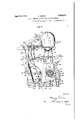
- FIG. 1 represents a right side elevation of a power operated ironing and pressing machine embodying my invention.
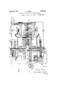
- Fig. 2 is a left side elevation of the same.
- Fig. 3 is a central vertical longitudinal section through the machine.
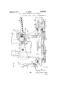
- Fig. 4 is an enlarged front elevation of the lower portion of the machine.
- Fig. 5 is a horizontal section of Fig. 4, on the line 5-5 thereof.
- Fig. 6 is a vertical section on the line 6'6 of Fig. 4.
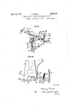
- Fig. 7 is an elevation of the controlling switch for the electric motor and the actuating means therefor.
- Fig. 8 is a horizontal section of theswitch mechanism.
- Fig. 9 is a detail perspective 'view illustrating the locking mechanism for the power actuated operating mechanism, and also illustrating means foractu'ating the movable arm of the controlling switch.
- Fig. 10 is a detail view illustrating a slight modification by which means are provided for locking the guard in operative position and for releasing the guard by means of a foot treadle instead of moving it by hand to its inoperative position.
- the main frame of the machine comprises a base 1, having an open standard 2, substantially square in cross section, projecting upwardly therefrom .with a rearwardly and upwardly extending arm 3, extending above and to the rear of the standard 2, and provided with means for supporting the pivotally mounted press head.
- Mounted upon the upper end of thestandard 2 is the support 4 for the stationary work support or lower buck, indicated at 5, the latter being of any desired shape or form, according to the character of work which the press is to be called upon to perform.
- the lower buck is preferably hollow and is provided interiorly with a heating chamber, indicated at 6, which may be supplied with steam, or the buck may be heated by other means, or may not be provided with heating means as preferred.
- the work support or buck is provided with the usual padding, indicated at 7 usually comprising a plurality of thicknesses of compressible fabrid covered by a cloth, the particular details of which are not material to the present invention.
- the main frame is also conveniently provided with a table or platform, indicated at 8, and secured to the main frame in any desired manner, for supporting portions of the garment or work being operated upon which are not supported by the buck.
- the movablepressing member comprises aress head, indicated at 9, which is pre erably.
- a pivoted frame or casting comprising a pair of arms 10, which are pivotally mounted between their ends upon a hollow shaft 11, or pivot, carried in the upper end of the rearwardly and upwardly extending arm 3, of the main frame, said arms being connected by transverse members to form a rigid pivoted frame.
- pivoted frame which carries the press head 9, is preferably provided with a downwardly The" to the rearwardly extendln portions ofthearms 10,'at 13, and exten s upwardly and forwardl therefrom, and is ad ustably connected with the frame preferably by means of abolt 14, threaded into the'cross bar 10 and extending through a sleeve 15, at the upper end of the arm 12, the said bolt being provided with a nut or collar 16 at one end of said sleeve and with a winged head 17 at the other end of said sleeve, so that the bolt may be rotated when desired to vary the adjustment-of the pre s head'with respect to the actuating arm 15.
- the press head is provided with a smooth lower'pressingface, which is heated in any desired manner.
- the-head is provided with an internal steamchamber above the pressing face through which steam is circulated by means of suitable pipe connections 18 extending to the hollow pivoted shaftll, and connecting with supply and return pipes 19 and 20, so that the supply of steam is not affected by the oscillations of 'the head at'the pivoted shaft 11 into and out of operative position.
- presses of this kind it is desirable to have thepress head when in open position at a considerable distance from the work :support or lower buck so as to facilitate theplacing and arranging 0f the garment or article to be ironed upon the work support, and this necessitates a movement of the upper pressing member or head through a considerable arc to and from its closed or pressing po sition.
- 21' represents acrank shaft mounted in bearings in the standard'2 of the main frame, and provided with crank arms 22 carrying a'crank pin 23.
- crank shaft, crank arms and crank pin may be formed of separated parts keyed or otherwise secured for joint rotation, as shown herein, or said parts may be formed as one integral casting or forging, if desired.
- a cross head 24 Surrounding the crank pin 23 is a cross head 24, in which is slidingly mounted a block 25 having a bearing aperture engaging the crank pin and capable of moving longitudinally in the cross head.
- a cushioning spring On each side of the block 25,.between'it and the end of the cross head, is a cushioning spring, said spring being indicated at 26, and
- This cross head is connected to the lower end of the actuating arm 12' for the movable pressing member, in this instance by means of a rod 28 which is screwed or otherwise secured to thecros's head and is provided at its upper end with a'block or casting 29 pivotally connected at 30 in the lower end of the arm 12.
- the cross head and" the rod 28 and block 29 form a connecting rod between the crank pin 23 and the actuating arm 12, and the springs 26'are so arranged as to cushion the starting and stopping movements of the press head, as will be readily understood.
- crank shaft 21 is provided with suitable means for. imparting intermittent motion thereto under the control of the operator for effecting the closing and opening movements of the press, andv in the arrangement shown 1n the drawings, each of such movements is accomplished by a half revolution of the crank shaft.
- the crank shaft is shown provided with a'driving gear 31 of considerable diameter, which meshes with a driving pinion 32 on'a driving shaft 33 to which the power is applied.
- I prefer 'to' provide an electric motor 34 for operating the. driving, shaft, and the pinion I 32 is formed in or secured to the motor shaft or arranged to be driven thereby in any de-' sired manner.
- the motor 34 may be conveniently supported on a bracket 35 secured to the main frame and provided with an auxiliary bearing, indicated at 36, for the motor'shaft, which in this instance has the pinion 32 formed or cut as an integral part of .the shaft on account of-its small diameter. Although this is not essential, it enables me to obtain the desired gear reduction without making the gear wheel 31 unduly large.
- crank shaft is operated always in the same direction, indicated by the-arrows in the various figures, I provide means for arresting the crank shaft at two separate points in its cycle, preferably separated 180.
- the arresting mechanism is preferably of such form as to bring the parts gently to rest with a cushioning effect to absorb a'nyshock,
- the actuating mechanism for the pressing members also includes the crank arms 22 and connecting rod 28 which in effect operate as toggle members which tend to maintain themselves in position when the toggles are straightened but which, when the toggle knuckle, to wit, crank pin 23, is moved to one side or the other, tend to open up, as a result of which it is desirable to stop the operating mechanism w' the toggles as nearly in full operative posi ion as possible.
- the arresting and locking mechanism which I prefer to employ is best illustrated in Figs; 6 and 9 and comprises the following elements.
- the locking bar 37 represents a horizontal sliding locking bar mounted in a guiding frame secured'to the base of the machine and comprising a bottom plate 38 and vertically disposed guides 39 at the front and rear end of the plate, having vertical slots formed therein in which the locking bar is inserted.
- the locking bar itself rests preferably upon fibre blocks 40, secured upon the upper face of the plate 38 and is limited in its longitudinal movement by transversely disposed pins or studs 41 in front and rear of the guides 39.
- the front end of the locking bar 37 is provided with a vertical arm 42, the upper'end of whichis provided with an arresting shoulder 43 adapted'to engage a portion of the crank, as indicated, for example, in Fig.
- crank being provided with a cushion or'buffer 44 preferably composed of a composition of fibre or other suitable material for cushioning the contact between the crank and arresting shoulder.
- the arm 42 is also provided with a pivoted locking lever 45,- pivoted at 46' and held in normal position by a spring 47 against a stop 48, this locking lever being in position to be engaged by a locking stud, indicated at 49, carried by the crank and'so arranged that as the crank approaches the arresting shoulder 43, the locking pin 49 will move the pivoted locking lever 45 forwardly until it passes off of the upper end thereof, when the locking lever 45 will drop back beneath the pin,- a'slindicated in Figs. 1 and 9, for example, so that the crank will remain locked, against movement until the locking bar 37 is shifted, as hereinafter described.
- the locking bar 37 is also provided, adjacent to its rear end, with a vertical arresting 'arm 42a, the upper end of which will engage the buffer 44 on the crank, for the purpose of" arresting the crank in its opposite position.
- I preferably provide a shock absorbing spring 50 beneath the locking bar, and said spring is conveniently-inserted in a recess in the bottom of the guide 39.
- the locking bar is also provided with a similar shock absorbing spring 51 atits forward end, which, however, is located above the bar, as the shock imparted to it when the crank engages the shoulder 43 is exerted in an upward direction, the said spring 51 being conveniently located in an aperture in the upper part of the forward guide 39, which aperture is closed by screw plug 52.
- shock absorbing springs 50, 51 have sufficient tension to produce the necessary retarding effect to bring the parts gently to rest and absorb anyshock, and when said springsare compressed so far as permitted by their mounting structure the moving locking bar 37 is positively brought to rest by positive limits reached by said bar at i the ends of the guides 39. Beyond this point the moving parts are not permitted to go until again released for the next operating movement.
- I also provide devices actuated by the operator for shifting the locking bar so as to disengage therefrom one set of locln'ng mechanism last engaged by the crank, and for applying power to the driving shaft and -crank shaft simultaneously, in this instance by starting the electric motor,and at-the same time, I provide means for shutting off the power applied to the driving shaft simultaneously with the arresting and locking of the crank, the result being thatthe press head will be swung down into pressing contact with the lower buck or worksupport and locked in position, or on the other hand, will be swung upward to its full position and locked therein under the control of the operator.
- an electric motor is employed' as t e source of power
- I employ in connection with the crank shaft or other rotating part driven by the motor, a switch mechanism, shown in detail in Figs. 7 and 8 and 9, which I conveniently employ on effecting the starting and stopping of the motor.
- 53 represents a rotary. switch ar which is loosely mounted in this instance on the crank shaft 21, and is provided with a I pair of brushes 54 yieldingly supported in connection therewith in any usual or desired manner, and in this instance being con: tact plates adapted to bridge over and connect two adjacent circular or segmental contacts.
- the crank shaft 21 is provided with a collar 55, carrying a driving plate 56 which engages the contact arm 53 for the pur' ose of driving it forwardly in the direction 0 rotation of the crank shaft, and a light spring 57 connects the switch arm 53 with the crank shaft so asto hold the arm 53 normally in engagement with the driving plate 56.
- This construction insures the rotation of the switch arm with the crankshaft when the latter is operated by motor, but permits the switch arm tobe advanced independently of the crank shaft, as will be readily understood.
- a switch plate 58 Adjacent to the'crank' shaft, I provide a switch plate 58 suitably supported'on the main frame provided with a plurality of concentric circular contact strips 61, 62, 63 and 64,'arranged concentrically with the axis of the crank shaft. These contact strips are preferably made circular for the purpose of affording a continuity of bearing surfaceto the brushes, but each of said circular conv of the dead segments of the switch and nocurrent will be supplied to the motor.
- the switch arm 53 in order to start the motor, the switch arm 53 must be moved from one of the dead segments to a live segment of the switch, when the motor will immediately start the rotation of the crank shaft and the crank will, through the driving plate 56, overtake the switch arm and carry it with the crank until it passes off of the live segment onto, the
- This frame comprises top and bottom 65 connectedby vertical bars 66 having a sliding engagement with guides .67 in this instance mounted on the switch board 58.
- the advancing frame is provided with two vertically disposed pivoted levers 68, each pivoted to one of the horizontal bars of the frame by bolt or stud69, and held inoperative the vertical movement of the frame will advance the switch arm 53 so as to carry it off of. the dead. segment on which it rests and onto the next adjacent live segment, thereby starting the motor, the operation of whic will continue until the switch arm has been carried by the half revolution of the crank shaft off of the live/segment and onto the next adjacent dead segment of the switch.
- the press is provided with a guard 7 4, preferably formed of sheet metal,
- the guard 74 is provided with a handle 7 7, by means of which the guard can be raised and lowered inde pendently of the press head, as indicated in Fig. 3, and means are provided for positively eonnecting the guard with the switch advancing frame and with the locking bar for the purpose of simultaneously releasing the power actuated operating mechanism and ap; plying power thereto.
- the casting which'forms the bearing 76 and to which the guard is connected is provided with a rearwardly extending arm 78 connected by a pivoted link 79 to an arm 80 on a rock shaft 81 mounted in hearings on the main frame and provided with a short vertically disposed arm82, which is connected by a link 83 with the horizontal locking bar 37.
- the vertical link 79 is also connected to one end of an oscillating lever 84 pivoted centrally at 85 to a suppor .”onnectedwith the main frame, the other end of the lever 84. being connected by link 86 with the cross bar of the advancing frame for the switch arm.
- the switchmechanism When the guard is in raised position, as shown in Figs. 1 and 3, the switchmechanism will be in the position indicated in Fig. 7, that is, the advancing arm is in raised position and the upper advancing arm 68 is in engagement with the stud 73, the switch arm being located substantially centrally of the left hand and rearmost dead segment of the switch. At this time the crank is looked, as
- the guard will be arrested in its descent before the switch arm 53 has been moved far enough to start the motor, so that the press cannot be operated into pressing position unless and until the guard 74 has been lovvered to such a position as to preclude the possibility of injury to the operator.
- the press head therefore descends into pressing position with considerable force, due to-its inertia of movement.
- the press head therefore, comes very firmly into contact with the padded work support, and exerts a very considerable pressure on the garment or other article to be pressed, determined by the adjustment of the press by means of the adjusting shaft 14.
- the motor circuit will be provided with the usual fuse (not shown) which will be blown out and prevent injury to the motor.
- fuse not shown
- crank shaft For convenience in rotating the crank shaft, in-case it should become :desir'ablefor any, reason to do so, I prefer to provide the crank shaft with a pivoted. hand lever .96 provided with a pawl 97 adapted to be moved into and out of'operative relation with the teeth of the gear wheel 31 by means of a rod 98 and normally held out of operative position.
- the arm 96 is conveniently-supported yleldingly at a convenient'poin't beneath the-table 8 by means of spring 99, which holds it. out of the way but permits it to be used' when desiredor necessary.
- the head being-raised and the crank locked by the arrestingand locking mechanism carried by the forward end of the lo'cking bar 37.
- the operator will spread the garment or other article to-be ironed or pressed upon the buck, and smooth out any wrinkles Y therein.
- the weight of the head assists the motor, and as there is no resistance to the downward movement of the head, the motor is 'thus enabled to attain its most effective operating speed and the head is quickly swung through the full are from its open to its closed position, thus bringing the head with considerable force and supplemented'by the inertia of the mass of the head, into contact with the garment on the padded work support;
- the forward shifting of the locking bar 37 has brought the arresting. arm 420, and locking device 45a on the rear portion of the locking bar into operative position to engage the crank at the conclusion of its movement, through 180 or half turn, as clearly illustrated in Fig. 6, and the crank and the head connected therewith is firmly locked with the head in closed pressing position.
- the power actuated mechanism will have been shut off just before, or just as the crank reaches its final locking, by reason of the fact that the rotation of the crank shaft will cause the driving plate 56 to overtake the switch arm and carry it away from the forked advancing arm 68, across the live segment of the lower part of the switch, and onto the dead segment at the forward part of the switch, leaving it in the position indicated in Fig. 2.
- the stud 73 on the switch arm will engage the forward advancing arm 68, pushing it to one side and seating itself in the forked portion thereof, as indicated in Fig. 2.
- the shock of arresting the head and crank is thoroughly cushioned by the padding on the buck, by the springs 26 in the cross head 24, by the cushioning spring 50 beneath the locking bar, and by the counter balance spring 94, if the same are employed.
- the counter balance springs are preferably slack at the beginning of the downward movement of the head, and these springs will exert a gradual increasing counter bal- I ancing effect as the head is moved downward through the last portion of its are, when the motor has acquired its full effective speed and power, leaving the counter balance springs in a state of tension ready to assist 1n the quick
- the shifting of the lockopening of the press on the next operation thereo The press is allowed to remain closed with the heated head in contact with the garment or other article to be ironed or pressed for a period determined by the operator, in accordance with the requirements with the work being performed, and the character of the goods or garments operated upon.
- the operator When it is desired to release the press and open it, the operator simply raises the guard to its original position, thereby shifting the locking bar rearwardly and raising the switch arm advancing frame.
- the switch arm having been left at the closing movement of the press, in the position indicated in Fig. 2, the forward forked arm 68 being in engagement with the stud on the switch arm, the upward movement of the advancing frame will shift the switch arm from the forward dead segment to the upper live segment of the switch, thus starting the motor, which instantly begins to operate the crank and raise the head.
- the counter balance springs 94 tend to assist the motor in lifting the head, and as there is no resistance to its upward movement, except the weight of the head, the motor quickly attains its speed and power, and quickly raises the head through its full arc to its highest position, where it is locked by the locking of the. crank, by means of the 45 at the forward end of the locking bar.
- the garment or other article is then removed from the buck, and another garment or article, or any portion of the same garment or article made ready on the buck for the next pressing operation.
- the form of advancing mechanism for the switch arm herein shown is such that each half revolution of the crank shaft must be completed so as to bring the shaft into locking position before the next operation can be accomplished. For example, if the crank was not revolved through 180, the stud 73 on the switch arm would be left in engagement with one of the advancing arms 68 without having entered the forked portion thereof, so that the switch arm could not be advanced for the next half revolution of the crank shaft until the preceding half revolution has been completed, so that the operations of the press must take place sequentially, as previously described.
- the rock shaft is provided with a locking arm 81?), which is engaged by a pawl 101, on a release lever 102, ih'mally supported by a spring 103, and adapted to be operated by the-foot of the operator, so that the operatorcan effect the upward movement of the head by depressing the foot lever 102, thereby releasing the locking arm 81?), and permitting the spring 100 to rockthe rock shaft 81a in the opposite direction, and effect the simultaneous movement of the locking bar 37, the guard, and the switch arm, to effect the lifting movement of the head.
- a press cloth may be used between the press head and the garment or article operated upon. This press cloth may be placed over the lower-face of and secured to the press head, or it may be laid upon the work and moisture maybe applied to the press cloth when desired, in any desired manner.
- What I claim is: 1, In an ironing and pressing machine, the combination with stationary and movable pressing members, power actuated means for moving said movable member into and out of pressing position, including an electric motor, a switch for controlling'said motor, including a movable switch arm adapted to be operated by the motor, an operator oper- "ated part movable independently of the movable pressing member into and out of 'ob- 'structing position at the entrance to the pressing space, connections between said part and said switch arm for moving the latter independently ofthe motor actuation thereof, andoperator operated means for simultaneously actuating said part and said switch arm.
- actuated means for moving said mova le member into and out of pressing position including an electric motor, a switch for controlling said motor, including a movable switch arm adapted to be operated'by the motor, an operator operated part movable independently of t e movable pressing member into and out of 0bstructing position'at the entrance to the pressing space, means for locking the movable pressing member in open and closed posi-- tion, connections between said part and said switch and said locking mechanism for securing the simultaneous actuation of the part and switch and the release of said locking mechanism, and operator operated means for-effecting said simultaneous actuation'of said parts. 4
- control comprising a reciprocating part and trip arms carried thereby for engagmg a part on said switch arm, a guard for the pressing space movable independently of the movable pressing member, and connections from said guard to said switch advancing means.
- a longitudinally movable locking bar crank ar-- resting and locking devices carried by said bar for locking the crank in two positions in its cycle, an electric motor operatively connected with the crank shaft, a controlling switch for the motor provided with live and dead segments, and a switch arm adapted to be actuated by the crank shaft but movable forwardly independently thereof, apivotally mounted guard for the pressing space independently movablewith respectto the pivoted pressing member, means for advancing the switch arm, and connections between said guard and said locking bar and said" switch arm advancing means for insuring the simultaneous actuation thereof.
- a power ironing and pressing machine the combination with a stationary padded work support, of a pivoted heated press ing member, an actuating crank shaft and crank, connections between said'crank and said pivoted pressing member, comprising a cross head, a part movably located therein, and engaging said crank, and cushioning springs on opposite sides of said part, a longitudinallymovable locking bar, crank arresting and locking devices carried by said bar for locking the crank in two positions in its cycle, an electric motor operatively con nected with the crank shaft, a controlling switch forthe motor provided with live and dead segments, and a switch arm adapted to be actuated by the crank shaft but movable forwardly independently thereof, a pivotally mounted guard for the pressing space inde' pendently movable with respect to the pivoted pressing member, means for advancing the switch arm, connections between said guard and said locking bar and said switch arm advancing means, and operator operated means for effecting the simultaneous move- Lnent of said guard, switch arm, and locking 11.
- a pressing machine comprising pressing members mounted for relative opening and closing movements, power actuating means for operating said members, means for stopping-relative movement of said members when they are in definite position. press locking means, and guarding means for the pressing members adapted to actuate said stopping and locking means and render said power actuating means eifective -,or ineffective.
- a pressing machine comprising press ing' members mounted for relative opening and closing movements, power actuating means for producing pressure between said members, press locking means, press releasing means, and guarding means for the pressing members adapted to actuate said looking and releasing means and render said power actuating means effective or inefi'ec- 13.
- a pressing machine comprising pressing members mounted for relative opening and closing movements, power actuating means for producing pressure between said members, press locking means, and guarding means for the pressing members adapted to actuate said locking means and to render said power actuating means effective or inefi'ec-- tive upon said pressing members.
- a pressing machine comprising press ing members mounted for relative opening and closing movements, means for stopping relative movement of said pressing'members when they are in definite position and for locking the same, and guarding means for the pressing members adapted to actuate said stopping and locking means.
- a pressing machine comprising pressing members mounted' f'or relative opening and closing movements, means for locking the pressing members, press releasing means, and guarding means for, the pressing members adapted to actuate said releasing and locking means.
- a pressing machine comprising pressing members mounted for relative opening and closing movements, power actuating means for producing pressure between said members, means for stopping relative movement of said members when they are in definite position, press locking means, press releasing means, and guarding means for the pressing members adapted to control operation of said power actuating means, stopping means, locking means and releasing means.
- a pressing machine of the ironing and pressing type including a stationary pressing member and a movable pressing member, an operator operated guard movable into and out of a position obstructing entrance to the space between said pressing members, power means for moving said pressing members into engagement, a controller for said power means, a single connection between said guard and said controller whereby operation of said motor means is effected only by the operation of said guard by the operator.
Landscapes
- Engineering & Computer Science (AREA)
- Textile Engineering (AREA)
- Press Drives And Press Lines (AREA)
Description
'April 12, 1932. H. PIERCE 1,853,375;-
POWER OPERATED IRONING AND PRESSING MACHINE Original Fil d A il 5, 1922 8 Sheets-Sheet 1 illlllllll-llllllllllllll April 12, 1932.
H. PIERCE POWER OPERATED IRONING AND PRESSING MACHINE Original Fil d April 5. 1922 8 Sheets-Sheet 2 J l 75 lo 1 r7 as [9 Y I '3 F I I Q 99. 92 7 a /9 L r 84 82 35 o o 9 88 9 0 ML 4/ gwwznfo'v April 12, PIERCE POWER OPERATED IRONING AND PRESSING MACHINE Original Filed April 5. 1922 8 Sheets-s 3 Roman April 12, 1932.
H. PIERCE 1,853,375
POWER OPERATED IRONING AND PRESSING MACHINE 8 Sheets-Sheet 4 inal Filed April 5, 1922 gwuwntoz H. PIERCE 1,853,375
POWER OPERATED IRONING AND PRESSING MACHINE April 12, 1932.
Original Filed April 5, 1922 8 Sheets$heet 5 anvcnto'o H. PIERCE April 12, 1932.
POWER OPERATED IRONING AND PRESSING MACHINE inal Filed April 5. 1922 8 Sheets-Sheet 6 H. PIERCE V A ril 12, 1932.
POWER OPERATED momma AND PRESSING MACHINE Original Filed April 5, 1922 8 Sheets-Sheet 7 7 f 55% ZZWY mumm H. PIERCE 1,853,375
POWER OPERATED IRONING AND PRESSING MACHINE April 12, 1 32.
Original Filed A ril 5, 1922 8 Sheets-Sheet 8 nbzntoz 1 mvu u attomew Patented Apr. 12, 1932 UNITED STATES PATENT OFFICE HARRY PIERCE, OF BROOKLYN, NEW YORK, ASSIGNOR TO THE AMERICAN LAUNDRY MACHINERY COMPANY, OF CINCINNATI, OHIO, A CORPORATION OF OHIO POWER OPERATE]? IRJONING AND PRESSING MACHINE Original application filed April 5, 1922, Serial No. 549,814, and in Canada February 2, 1923. Divided and this application filed November 10, 1927. Serial No. 232,420.
My invention consists in the novel features hereinafter described, reference being had to the accompanying drawings which illustrate one embodiment of my invention selected by me for purposes of illustration and the said invention is fully disclosed in the following description and claims.
The object of my invention is to provide a tion of parts which are hereinafter fully described and illustrated in the accompanying drawings.
This application is a division of my prior patent for power operated ironing and pressing machine, granted November 6, 1928, No. 1,690,431.
In the drawings Fig. 1 represents a right side elevation of a power operated ironing and pressing machine embodying my invention.
Fig. 2 is a left side elevation of the same. a
Fig. 3 is a central vertical longitudinal section through the machine.
Fig. 4 is an enlarged front elevation of the lower portion of the machine.
Fig. 5 is a horizontal section of Fig. 4, on the line 5-5 thereof.
Fig. 6 is a vertical section on the line 6'6 of Fig. 4.
Fig. 7 is an elevation of the controlling switch for the electric motor and the actuating means therefor. I
Fig. 8 is a horizontal section of theswitch mechanism.
Fig. 9 is a detail perspective 'view illustrating the locking mechanism for the power actuated operating mechanism, and also illustrating means foractu'ating the movable arm of the controlling switch.
Fig. 10 is a detail view illustrating a slight modification by which means are provided for locking the guard in operative position and for releasing the guard by means of a foot treadle instead of moving it by hand to its inoperative position.
The main frame of the machine comprises a base 1, having an open standard 2, substantially square in cross section, projecting upwardly therefrom .with a rearwardly and upwardly extending arm 3, extending above and to the rear of the standard 2, and provided with means for supporting the pivotally mounted press head. Mounted upon the upper end of thestandard 2 is the support 4 for the stationary work support or lower buck, indicated at 5, the latter being of any desired shape or form, according to the character of work which the press is to be called upon to perform. The lower buck is preferably hollow and is provided interiorly with a heating chamber, indicated at 6, which may be supplied with steam, or the buck may be heated by other means, or may not be provided with heating means as preferred. The work support or buck is provided with the usual padding, indicated at 7 usually comprising a plurality of thicknesses of compressible fabrid covered by a cloth, the particular details of which are not material to the present invention. The main frame is also conveniently provided with a table or platform, indicated at 8, and secured to the main frame in any desired manner, for supporting portions of the garment or work being operated upon which are not supported by the buck. The movablepressing member comprises aress head, indicated at 9, which is pre erably. pivotally mounted, and in this instance is carried by the forward end of a pivoted frame or casting comprising a pair of arms 10, which are pivotally mounted between their ends upon a hollow shaft 11, or pivot, carried in the upper end of the rearwardly and upwardly extending arm 3, of the main frame, said arms being connected by transverse members to form a rigid pivoted frame. pivoted frame which carries the press head 9, is preferably provided with a downwardly The" to the rearwardly extendln portions ofthearms 10,'at 13, and exten s upwardly and forwardl therefrom, and is ad ustably connected with the frame preferably by means of abolt 14, threaded into the'cross bar 10 and extending through a sleeve 15, at the upper end of the arm 12, the said bolt being provided with a nut or collar 16 at one end of said sleeve and with a winged head 17 at the other end of said sleeve, so that the bolt may be rotated when desired to vary the adjustment-of the pre s head'with respect to the actuating arm 15.
The press head is provided with a smooth lower'pressingface, which is heated in any desired manner. Preferably the-head is provided with an internal steamchamber above the pressing face through which steam is circulated by means of suitable pipe connections 18 extending to the hollow pivoted shaftll, and connecting with supply and return pipes 19 and 20, so that the supply of steam is not affected by the oscillations of 'the head at'the pivoted shaft 11 into and out of operative position. In presses of this kind, it is desirable to have thepress head when in open position at a considerable distance from the work :support or lower buck so as to facilitate theplacing and arranging 0f the garment or article to be ironed upon the work support, and this necessitates a movement of the upper pressing member or head through a considerable arc to and from its closed or pressing po sition. The opening and closingmovements of presses of this kind have usually been accomplished by means of levers-actuated by the operators foot, but in my press such foot levers are dispensed with and the entire movement of the res's head into pressing position is accomplish ating mechanism hereinafter described; In the embodiment of my invention herein shown, 21' represents acrank shaft mounted in bearings in the standard'2 of the main frame, and provided with crank arms 22 carrying a'crank pin 23. The crank shaft, crank arms and crank pin may be formed of separated parts keyed or otherwise secured for joint rotation, as shown herein, or said parts may be formed as one integral casting or forging, if desired. Surrounding the crank pin 23 is a cross head 24, in which is slidingly mounted a block 25 having a bearing aperture engaging the crank pin and capable of moving longitudinally in the cross head. On each side of the block 25,.between'it and the end of the cross head, is a cushioning spring, said spring being indicated at 26, and
being retained in'position in any desired way, as by engaging lugs 27 on the opposite faces of the block 25, and at the opposite ends of ed by the power actuated 0per-' the cross head. This cross head is connected to the lower end of the actuating arm 12' for the movable pressing member, in this instance by means of a rod 28 which is screwed or otherwise secured to thecros's head and is provided at its upper end with a'block or casting 29 pivotally connected at 30 in the lower end of the arm 12. The cross head and" the rod 28 and block 29 form a connecting rod between the crank pin 23 and the actuating arm 12, and the springs 26'are so arranged as to cushion the starting and stopping movements of the press head, as will be readily understood. The crank shaft 21 is provided with suitable means for. imparting intermittent motion thereto under the control of the operator for effecting the closing and opening movements of the press, andv in the arrangement shown 1n the drawings, each of such movements is accomplished by a half revolution of the crank shaft. In this instance the crank shaft is shown provided with a'driving gear 31 of considerable diameter, which meshes with a driving pinion 32 on'a driving shaft 33 to which the power is applied. I prefer 'to' provide an electric motor 34 for operating the. driving, shaft, and the pinion I 32 is formed in or secured to the motor shaft or arranged to be driven thereby in any de-' sired manner. I prefer to employ a very small' driving pinion, thus securin a large gear reduction between the motor s aftand the crank shaft, and as the greater part of I the movements of the upper press head in 1-00 both. directions require only suflicient power -to move the head and the connected parts, the construction .herein shown is admirably adapted for use with an electric'motor of' small power and correspondingly small current consumption and enables the motor to quickly acquire its normal operating speed. The motor 34 may be conveniently supported on a bracket 35 secured to the main frame and provided with an auxiliary bearing, indicated at 36, for the motor'shaft, which in this instance has the pinion 32 formed or cut as an integral part of .the shaft on account of-its small diameter. Although this is not essential, it enables me to obtain the desired gear reduction without making the gear wheel 31 unduly large.
As the crank shaft is operated always in the same direction, indicated by the-arrows in the various figures, I provide means for arresting the crank shaft at two separate points in its cycle, preferably separated 180.
and in. association with the arresting means I prefer to provide means for positively locking the crank shaft and the parts connected therewith against movement, so as to insure the proper operation of the pressat all times. The arresting mechanism is preferably of such form as to bring the parts gently to rest with a cushioning effect to absorb a'nyshock,
leaving the operating mechanism and pressing members in reasonably definite position both in open and closed full pressure positions of the press, the arresting movement being terminated positively with the parts in a limited position beyond which they cannot go. Such arrest is desirable. to prevent the operating mechanism from in any manner over-running and thereby moving the pressing members to a position of less pressure or efficiency, after they have been moved to the position in which the best pressing effects are obtained. The actuating mechanism for the pressing members also includes the crank arms 22 and connecting rod 28 which in effect operate as toggle members which tend to maintain themselves in position when the toggles are straightened but which, when the toggle knuckle, to wit, crank pin 23, is moved to one side or the other, tend to open up, as a result of which it is desirable to stop the operating mechanism w' the toggles as nearly in full operative posi ion as possible. The arresting and locking mechanism which I prefer to employ is best illustrated in Figs; 6 and 9 and comprises the following elements. 37 represents a horizontal sliding locking bar mounted in a guiding frame secured'to the base of the machine and comprising a bottom plate 38 and vertically disposed guides 39 at the front and rear end of the plate, having vertical slots formed therein in which the locking bar is inserted. The locking bar itself rests preferably upon fibre blocks 40, secured upon the upper face of the plate 38 and is limited in its longitudinal movement by transversely disposed pins or studs 41 in front and rear of the guides 39. The front end of the locking bar 37 is provided with a vertical arm 42, the upper'end of whichis provided with an arresting shoulder 43 adapted'to engage a portion of the crank, as indicated, for example, in Fig. 1,the crank being provided with a cushion or'buffer 44 preferably composed of a composition of fibre or other suitable material for cushioning the contact between the crank and arresting shoulder. a The arm 42 is also provided with a pivoted locking lever 45,- pivoted at 46' and held in normal position by a spring 47 against a stop 48, this locking lever being in position to be engaged by a locking stud, indicated at 49, carried by the crank and'so arranged that as the crank approaches the arresting shoulder 43, the locking pin 49 will move the pivoted locking lever 45 forwardly until it passes off of the upper end thereof, when the locking lever 45 will drop back beneath the pin,- a'slindicated in Figs. 1 and 9, for example, so that the crank will remain locked, against movement until the locking bar 37 is shifted, as hereinafter described.
The locking bar 37 is also provided, adjacent to its rear end, with a vertical arresting 'arm 42a, the upper end of which will engage the buffer 44 on the crank, for the purpose of" arresting the crank in its opposite position.
or shoulder 45?; and a curved or inclined face 450, as best shown in Fig, 9, said locking bar being held in its normal position by a spring 47a against a stop 48a. It will readily be understood, b, refer- 'ence to Fig. 9, for example, that the locking bar 37 may be moved longitudinally so as to release the crank in either position in which it may be locked, and when the rotation of the crank toward the rear is effected, the crank will be stopped by the arresting arm 42a, and the locking pin 49 will push the looking lever 45a rearwardly until it passes beneath the same and is locked thereto, as indicated in Fig. 6. As the shock in arresting the crank in its rear position, as indicated in Fig. 6, is exerted in a downward direction, I preferably provide a shock absorbing spring 50 beneath the locking bar, and said spring is conveniently-inserted in a recess in the bottom of the guide 39. The locking bar is also provided with a similar shock absorbing spring 51 atits forward end, which, however, is located above the bar, as the shock imparted to it when the crank engages the shoulder 43 is exerted in an upward direction, the said spring 51 being conveniently located in an aperture in the upper part of the forward guide 39, which aperture is closed by screw plug 52. The shock absorbing springs 50, 51 have sufficient tension to produce the necessary retarding effect to bring the parts gently to rest and absorb anyshock, and when said springsare compressed so far as permitted by their mounting structure the moving locking bar 37 is positively brought to rest by positive limits reached by said bar at i the ends of the guides 39. Beyond this point the moving parts are not permitted to go until again released for the next operating movement.
In connection with the foregoing mechanism, I also provide devices actuated by the operator for shifting the locking bar so as to disengage therefrom one set of locln'ng mechanism last engaged by the crank, and for applying power to the driving shaft and -crank shaft simultaneously, in this instance by starting the electric motor,and at-the same time, I provide means for shutting off the power applied to the driving shaft simultaneously with the arresting and locking of the crank, the result being thatthe press head will be swung down into pressing contact with the lower buck or worksupport and locked in position, or on the other hand, will be swung upward to its full position and locked therein under the control of the operator.
In the embodiment of the invention shown herein, in hich an electric motor is employed' as t e source of power, I employ in connection with the crank shaft or other rotating part driven by the motor, a switch mechanism, shown in detail in Figs. 7 and 8 and 9, which I conveniently employ on effecting the starting and stopping of the motor. As erein shown, 53 represents a rotary. switch ar which is loosely mounted in this instance on the crank shaft 21, and is provided with a I pair of brushes 54 yieldingly supported in connection therewith in any usual or desired manner, and in this instance being con: tact plates adapted to bridge over and connect two adjacent circular or segmental contacts. The crank shaft 21 isprovided with a collar 55, carrying a driving plate 56 which engages the contact arm 53 for the pur' ose of driving it forwardly in the direction 0 rotation of the crank shaft, and a light spring 57 connects the switch arm 53 with the crank shaft so asto hold the arm 53 normally in engagement with the driving plate 56. This construction insures the rotation of the switch arm with the crankshaft when the latter is operated by motor, but permits the switch arm tobe advanced independently of the crank shaft, as will be readily understood. Adjacent to the'crank' shaft, I provide a switch plate 58 suitably supported'on the main frame provided with a plurality of concentric circular contact strips 61, 62, 63 and 64,'arranged concentrically with the axis of the crank shaft. These contact strips are preferably made circular for the purpose of affording a continuity of bearing surfaceto the brushes, but each of said circular conv of the dead segments of the switch and nocurrent will be supplied to the motor. Ob-
viously, in order to start the motor, the switch arm 53 must be moved from one of the dead segments to a live segment of the switch, when the motor will immediately start the rotation of the crank shaft and the crank will, through the driving plate 56, overtake the switch arm and carry it with the crank until it passes off of the live segment onto, the
opposite dead segment, thereby cutting of? current to the motor and facilitating the arresting and stopping of the crank and its connected mechanism. i
For-the purpose of advancing the switch arm soas to start the motor, I conveniently employ a rectangular reciprocating frame which I term the switch arm advancing frame, and which is clearly shown in Fig. 7.
ars
.This frame comprises top and bottom 65 connectedby vertical bars 66 having a sliding engagement with guides .67 in this instance mounted on the switch board 58. The advancing frame is provided with two vertically disposed pivoted levers 68, each pivoted to one of the horizontal bars of the frame by bolt or stud69, and held inoperative the vertical movement of the frame will advance the switch arm 53 so as to carry it off of. the dead. segment on which it rests and onto the next adjacent live segment, thereby starting the motor, the operation of whic will continue until the switch arm has been carried by the half revolution of the crank shaft off of the live/segment and onto the next adjacent dead segment of the switch.
As the ,upper pressing member or press.
head has considerable weight and is swung quickly down uponthe lower pressing memberor buck into final pressing position, injury to the hands of the operator might result if they were not entirely removed from the buck or work support before the descent of the press head. I prefer, therefore, to employ in conjunction with my press a guard movable independently of the ress head, and so connected with the means or releasing the locking mechanism for the crank and starting the operation of the power actuating operating means, that'power cannot be-applied to move the head toward pressing position until the guard, which preferablyentirely surrounds the buck or work support when in operative position, has been lowered to such position as to preclude the'possibility of the operators hands. being caught between the pressingmembers. In themachine herein shown, I have illustrated such a guard, constructed and arranged so that the guard itself is lowered into operative position and simultaneously .unlocks the crank and advances the switch arm so as to start the motor, but
I do notlimit myself to this construction as it isonly necessary that the said parts shall 'be simultaneously actuated and they may be operated either by manually operating the guard or by actuating it through other means. As herein shown, the press is provided with a guard 7 4, preferably formed of sheet metal,
wire gauze, or other light material, and supported by a guard frame7 5 which is pivotally mounted by means of bearings 76 upon the shaft 11, on which the upper press head is pivoted. In this instance the guard 74 is provided with a handle 7 7, by means of which the guard can be raised and lowered inde pendently of the press head, as indicated in Fig. 3, and means are provided for positively eonnecting the guard with the switch advancing frame and with the locking bar for the purpose of simultaneously releasing the power actuated operating mechanism and ap; plying power thereto. To this end the casting which'forms the bearing 76 and to which the guard is connected, is provided with a rearwardly extending arm 78 connected by a pivoted link 79 to an arm 80 on a rock shaft 81 mounted in hearings on the main frame and provided with a short vertically disposed arm82, which is connected by a link 83 with the horizontal locking bar 37. The vertical link 79 is also connected to one end of an oscillating lever 84 pivoted centrally at 85 to a suppor ."onnectedwith the main frame, the other end of the lever 84. being connected by link 86 with the cross bar of the advancing frame for the switch arm.
It will thus be seen, especially by reference to Fig. 2, that when the guard 74 is brought down into operative position so as to substantially enclose the pressing members and to prevent the possibility of accident, the looking bar will be moved to its most forward position, thereby releasingthe crank from the arresting and locking devices carried at the forward end of the locking bar, and bringing those at the rear end of the bar into operative position, and simultaneously the advancing frame for the switch arm will be drawn down into its lowest position, causing the switch arm to be advanced to the lower live segment of the switch and setting in motion the motor and the crank shaft, and thereby swinging the press head downward into pressing position, where it is locked by the arresting and-locking devices at the rear end of the locking bar 37. The parts I have shown in Fig. 2 as they appear at the conclusion 'of this movement, the switch arm having been carried by the crank shaft onto the right hand or forward dead segment of the switch. It will also be seen that when the guard 74 is raised, the locking bar will be shifted to the rear and the advancing frame will be raised, thereby advancing the switch arm to the upper live segment, starting the motor and swinging the press head to raised position, where it will be held by the arresting and locking mechanism perfectly obvious, therefore, that as the guard perfectly obvious, therefore, that as the guard 74, the locking bar 37, and the controlling mechanism for the motor are coupled together for joint and simultaneous movement, the op a erators hand (or foot) could be applied at any convenient point on any part of the connected mechanism to effect the joint and simultaneous movement of the several parts. I find it convenient to set these parts in motion by means of a handle applied to the guard, and operated by the hand of the operator, but I wish it to be understood that these connected parts can be simultaneously actuated by the operator in any desired manner.
I prefer to provide the guard 74 with counter balance mechanism, comprising in this instance, counter balance springs 87, and I also provide means for limiting the movement of the guard adjustably, consisting in this instance of a stop rod 88, connected to the-arm 78, and a similar arm89, secured to the other bearing casting of the guard, and extending downwardly through guiding apertures in brackets 90, secured to the main frame (see Figs. 1 and 2), the rods 88 being provided with threaded portions, carrying stop nuts 91, or stop collars for engaging the brackets 90 and limiting the downward and also'the upward movements of the guard.
When the guard is in raised position, as shown in Figs. 1 and 3, the switchmechanism will be in the position indicated in Fig. 7, that is, the advancing arm is in raised position and the upper advancing arm 68 is in engagement with the stud 73, the switch arm being located substantially centrally of the left hand and rearmost dead segment of the switch. At this time the crank is looked, as
shown in Fig. 3, by the arresting and locking devices at the forward end of the locking bar 37. It will be seen, therefore, that as the guard is lowered into its operative position, indicated in dotted lines in Fig. 3, the switch arm 53-willbe moved a considerable distance toward the lower live segment of the switch before its brushes will make contact with the contacts thereof, and the connections between the guard and the locking lever and the switch advancing frame are so adjusted, as before stated, that the switch arm 53 will not be moved into operative relation with the live segment, nor will the crank be released from thelocking mechanism, until the guard 74 has been fully brought into its operative position. Should the end portion of the operators handrest upon the work support and buck, the guard will be arrested in its descent before the switch arm 53 has been moved far enough to start the motor, so that the press cannot be operated into pressing position unless and until the guard 74 has been lovvered to such a position as to preclude the possibility of injury to the operator.
It will be noted that as the pressing head I ance so that the motor may quickly attain its eflective operating speed. Moreover, the press head possesses considerable weight, and
therefore descends into pressing position with considerable force, due to-its inertia of movement. The press head, therefore, comes very firmly into contact with the padded work support, and exerts a very considerable pressure on the garment or other article to be pressed, determined by the adjustment of the press by means of the adjusting shaft 14. I prefer to provide what I term an emergency stop for' arresting the downward movement'of the press head in case it is so adjusted as not to make contact with the garment on the padded work support; In this instance I have shown a metal strap 92 secured to the rearwardly and upwardly ex.- tending arm 3 of the press frame, and pro-' vided with an elastic yieldin cushioning stop 93 'to engage the downwardly extending arm 12 for the press head. Should the-adjustment of the press head be such that the press head cannot be forced downward far enough to permit thelocking of the crank shaft and the movement of the switch arm by the crank shaft to the proper dead seg ment of theswitch for stopping the motor, the motor circuit will be provided with the usual fuse (not shown) which will be blown out and prevent injury to the motor. These fuses can be replaced in a few-moment's, in
case the press is stopped in this manner. It is not necessary to counter balance the press used, therefore, only slightly check the clos-' ing movement ofthe press head, while their force is utilized during the first partof the opening movement of the'p'ress, when the motor is beginning to rotate, the crank shaft, the springs becoming practically slack; before the head reaches its uppermost position,
j sothat the springs. do not have to be overcome.
in arresting or checking the upward movement of the press head.
While the movement of the. press head is Positively arrested at, the close of itsdownward and upward movements, this is accomplished Without any material 'shockto the apparatus, On'the-downward stroke of the press head, the impact of-the head itself is cushioned by the padded work support, and.
"the garment or other article operated on, and
also by means of the cushioning springs 26' in the cross head 24 and also by the spring 50 and fibre block 40 beneath the locking bar 37 On the upward movement of the press head, it is arrested by thearresting and stopswitch only when the guard has reached iping mechanism at the forward'end of the locking bar,'the press head being relievedof the lifting force of the counter balance s rin s 94 before reachin its final position,
P g g as be ore described, and the force of its' arrest is cushionedby the springs 26 of the cross head 24 and alsoby the spring 51 above the forward end of thel'ocking bar. It follows, therefore, that the operation of the press head in both directions is rapid, effective and ceases instantaneously as the press head arrivesat its pressing or open position,
in which it is locked without noticeable'shock and jar; These cushioning devices also cooperate with the padded work support in accommodating slight variations in the thickness of the garments or other articles operated upon. Greatervariations'in thickness in such garments or other articles can-be readil accommodated by the adjustment rovi ed between'the press head and actuating arm 12 by turning the screw bolt 14.
For convenience in rotating the crank shaft, in-case it should become :desir'ablefor any, reason to do so, I prefer to provide the crank shaft with a pivoted. hand lever .96 provided with a pawl 97 adapted to be moved into and out of'operative relation with the teeth of the gear wheel 31 by means of a rod 98 and normally held out of operative position. The arm 96 is conveniently-supported yleldingly at a convenient'poin't beneath the-table 8 by means of spring 99, which holds it. out of the way but permits it to be used' when desiredor necessary.
The operation of my improved press is as follows :The normal posltion of the press when in'open position is as shown in Figs. 1
and 3, the head being-raised and the crank locked by the arrestingand locking mechanism carried by the forward end of the lo'cking bar 37. The operator will spread the garment or other article to-be ironed or pressed upon the buck, and smooth out any wrinkles Y therein. The operator-will then actuate the guard 7 4 and its connected mechanism, in this instance by placing the hand on the handle ,or
' The power actuated mechanism will have been shut off just before, or just as the crank reaches its final locking, by reason of the fact that the rotation of the crank shaft will cause the driving plate 56 to overtake the switch arm and carry it away from the forked advancing arm 68, across the live segment of the lower part of the switch, and onto the dead segment at the forward part of the switch, leaving it in the position indicated in Fig. 2. The stud 73 on the switch arm will engage the forward advancing arm 68, pushing it to one side and seating itself in the forked portion thereof, as indicated in Fig. 2. As beforestated, the shock of arresting the head and crank is thoroughly cushioned by the padding on the buck, by the springs 26 in the cross head 24, by the cushioning spring 50 beneath the locking bar, and by the counter balance spring 94, if the same are employed. As before stated, the counter balance springs'are preferably slack at the beginning of the downward movement of the head, and these springs will exert a gradual increasing counter bal- I ancing effect as the head is moved downward through the last portion of its are, when the motor has acquired its full effective speed and power, leaving the counter balance springs in a state of tension ready to assist 1n the quick The shifting of the lockopening of the press on the next operation thereo The press is allowed to remain closed with the heated head in contact with the garment or other article to be ironed or pressed for a period determined by the operator, in accordance with the requirements with the work being performed, and the character of the goods or garments operated upon. When it is desired to release the press and open it, the operator simply raises the guard to its original position, thereby shifting the locking bar rearwardly and raising the switch arm advancing frame. The switch arm having been left at the closing movement of the press, in the position indicated in Fig. 2, the forward forked arm 68 being in engagement with the stud on the switch arm, the upward movement of the advancing frame will shift the switch arm from the forward dead segment to the upper live segment of the switch, thus starting the motor, which instantly begins to operate the crank and raise the head. The counter balance springs 94, if employed, tend to assist the motor in lifting the head, and as there is no resistance to its upward movement, except the weight of the head, the motor quickly attains its speed and power, and quickly raises the head through its full arc to its highest position, where it is locked by the locking of the. crank, by means of the 45 at the forward end of the locking bar. The garment or other article is then removed from the buck, and another garment or article, or any portion of the same garment or article made ready on the buck for the next pressing operation. During this upward movement of the head, the driving plate 56 on the crank shaft will overtake the switch arm and carry it across the upper live segment of the switch to the dead segment at the rear side of the switch, thus shutting off the power, and the stud 7 3 on the switch arm will push the advancing arm 68 to the rear and place itself within the forked prtion of the advancing arm, ready for the next operation, as shown inFig. 7
The form of advancing mechanism for the switch arm herein shown is such that each half revolution of the crank shaft must be completed so as to bring the shaft into locking position before the next operation can be accomplished. For example, if the crank was not revolved through 180, the stud 73 on the switch arm would be left in engagement with one of the advancing arms 68 without having entered the forked portion thereof, so that the switch arm could not be advanced for the next half revolution of the crank shaft until the preceding half revolution has been completed, so that the operations of the press must take place sequentially, as previously described.
As before stated it is not essential that the part which is manipulated by -the operator arresting shoulder 43 and locking member I should be located on the guard, as the handle 77 although I find this very convenient; It is only necessary that some part accessible to the operator be manipulated for the purpose of effecting the simultaneous actuation of the shiftin lever and power mechanism, and preferjbly the guard, which could be accomplished in other ways. For example, in Fig. 10, I have illustrated a slight modification of the operator operated mechanism, in which the rock shaft, here designated 81a, is pro- Vided with a foot lever 77a, connected therc with against a retracting spring 100 for the purpose of effecting the simultaneous movement of the guard to downward position, of
, the lockingbar to forwardpositicn, and of the switch arm to operative position, for the purpose of closing the press. In this modification the rock shaft" is provided with a locking arm 81?), which is engaged by a pawl 101, on a release lever 102, ih'mally supported by a spring 103, and adapted to be operated by the-foot of the operator, so that the operatorcan effect the upward movement of the head by depressing the foot lever 102, thereby releasing the locking arm 81?), and permitting the spring 100 to rockthe rock shaft 81a in the opposite direction, and effect the simultaneous movement of the locking bar 37, the guard, and the switch arm, to effect the lifting movement of the head. I do not, how! ever, desire to be limited to the specific means by which the operator can manipulate the con- -trol mechanisms of the press, as these may he obviously varied somewhat, as convenience may dictate, without'departing from the in vention.
When the press is used-for pressing extremely delicate fabric, or for pressing woolen or other articles, a press cloth may be used between the press head and the garment or article operated upon. This press cloth may be placed over the lower-face of and secured to the press head, or it may be laid upon the work and moisture maybe applied to the press cloth when desired, in any desired manner.
What I claim is: 1, In an ironing and pressing machine, the combination with stationary and movable pressing members, power actuated means for moving said movable member into and out of pressing position, including an electric motor, a switch for controlling'said motor, including a movable switch arm adapted to be operated by the motor, an operator oper- "ated part movable independently of the movable pressing member into and out of 'ob- 'structing position at the entrance to the pressing space, connections between said part and said switch arm for moving the latter independently ofthe motor actuation thereof, andoperator operated means for simultaneously actuating said part and said switch arm.
2. In an ironing-and. pressing machine,
the combination with stationary and movable pressing members, ower actuated means for moving said mova le member into and out of pressing position, including an electric motor, a switch for controlling said motor, including a movable switch arm adapted to be operated'by the motor, an operator operated part movable independently of t e movable pressing member into and out of 0bstructing position'at the entrance to the pressing space, means for locking the movable pressing member in open and closed posi-- tion, connections between said part and said switch and said locking mechanism for securing the simultaneous actuation of the part and switch and the release of said locking mechanism, and operator operated means for-effecting said simultaneous actuation'of said parts. 4
3. In an ironing and pressing machine, the combination [with stationary and movable pressing members, of power actuated operating means for moving the movable pressing member into and out of pressing position, a
part movable independently of the movable pressing member into and out of a position obstructing the entrance to the. pressing sgace, locking means for locking the mova le pressing member in open and closed positions, and operator operated means for simultaneously actuating said locking means, said power operating mechanism and said part. 1 v
4. In an ironing and pressing machine, the combination with stationary and movable pressing members, of a crank shaft and crank connections from the crank to the movable pressing member for moving it into and out of pressing position, locking mechanism for locking the crank shaft in two positions at separated points in its cycle, means for applying power to-said shaft, a controllerfor said pressing members, movable independently of said movable pressing member into and out of obstructing position at the entrance to the pressing space, controlling means for said power applying means, and
connections from said controller to said locking mechanism and said controlling means for effecting the simultaneous movements obstructing position at the entrance to the same.
6. In an ironing and pressing machine,the combinatlon with stationary and movable pressing members, motor actuated means for moving the movable pressing member into and out of pressing position, an electric mow tor therefor, a controlling switch for said motor provided with live and dead segments, and a movable switch arm driven by the m0- tor, but capable of movement forwardlyindependently thereof, means for advancing said switch arm independently of its motor control, a device movable independently of the movable pressing member into and out of obstructing position at the entrance to the pressing space, and connections between said device and the switch arm advancing means.
7. In an ironing and pressing machine, the combination with stationary and movable pressing members,motor actuated means for movingthe movable pressing member into and out of pressing position, an electric motor therefor, a controlling switch for said motor provided with live and dead segments, and a movable switch arm driven by the motor, but capable of movement forwardly independently thereof, means for advancing said switch arm independently of its motor.
control, comprising a reciprocating part and trip arms carried thereby for engagmg a part on said switch arm, a guard for the pressing space movable independently of the movable pressing member, and connections from said guard to said switch advancing means.
8. In an ironing and pressing machine, the combination with stationary and movable pressing members, motor actuated means for moving the movable pressing member into and out of pressing position, an electric motor therefor, a controlling switch for said motor provided with live and dead segments,
and a movable switch arm driven by the mo- "tor, but capable of movement forwardly inoperator operated means for simultaneously ing means.
9. In a power ironing and pressing machine, the combination with a stationary padded work support, of a pivoted heated pressing member, an actuating crank shaft, and crank connections between said crankean'd said 'pivoted pressing member, comprising a cross head, a part movably located therein, and engaging said crank, and cushioning actuating said device and the switch advanctive.
springs on opposite sides of said part, a longitudinally movable locking bar, crank ar-- resting and locking devices carried by said bar for locking the crank in two positions in its cycle, an electric motor operatively connected with the crank shaft, a controlling switch for the motor provided with live and dead segments, and a switch arm adapted to be actuated by the crank shaft but movable forwardly independently thereof, apivotally mounted guard for the pressing space independently movablewith respectto the pivoted pressing member, means for advancing the switch arm, and connections between said guard and said locking bar and said" switch arm advancing means for insuring the simultaneous actuation thereof.
10. In a power ironing and pressing machine, the combination with a stationary padded work support, of a pivoted heated press ing member, an actuating crank shaft and crank, connections between said'crank and said pivoted pressing member, comprising a cross head, a part movably located therein, and engaging said crank, and cushioning springs on opposite sides of said part, a longitudinallymovable locking bar, crank arresting and locking devices carried by said bar for locking the crank in two positions in its cycle, an electric motor operatively con nected with the crank shaft, a controlling switch forthe motor provided with live and dead segments, and a switch arm adapted to be actuated by the crank shaft but movable forwardly independently thereof, a pivotally mounted guard for the pressing space inde' pendently movable with respect to the pivoted pressing member, means for advancing the switch arm, connections between said guard and said locking bar and said switch arm advancing means, and operator operated means for effecting the simultaneous move- Lnent of said guard, switch arm, and locking 11. A pressing machine, comprising pressing members mounted for relative opening and closing movements, power actuating means for operating said members, means for stopping-relative movement of said members when they are in definite position. press locking means, and guarding means for the pressing members adapted to actuate said stopping and locking means and render said power actuating means eifective -,or ineffective.
12. A pressing machine, comprising press ing' members mounted for relative opening and closing movements, power actuating means for producing pressure between said members, press locking means, press releasing means, and guarding means for the pressing members adapted to actuate said looking and releasing means and render said power actuating means effective or inefi'ec- 13. A pressing machine, comprising pressing members mounted for relative opening and closing movements, power actuating means for producing pressure between said members, press locking means, and guarding means for the pressing members adapted to actuate said locking means and to render said power actuating means effective or inefi'ec-- tive upon said pressing members.
14. A pressing machine, comprising press ing members mounted for relative opening and closing movements, means for stopping relative movement of said pressing'members when they are in definite position and for locking the same, and guarding means for the pressing members adapted to actuate said stopping and locking means.
15. A pressing machine, comprising pressing members mounted' f'or relative opening and closing movements, means for locking the pressing members, press releasing means, and guarding means for, the pressing members adapted to actuate said releasing and locking means.
16. A pressing machine, comprising pressing members mounted for relative opening and closing movements, power actuating means for producing pressure between said members, means for stopping relative movement of said members when they are in definite position, press locking means, press releasing means, and guarding means for the pressing members adapted to control operation of said power actuating means, stopping means, locking means and releasing means.
17. In a pressing machine of the ironing and pressing type, including a stationary pressing member and a movable pressing member, an operator operated guard movable into and out of a position obstructing entrance to the space between said pressing members, power means for moving said pressing members into engagement, a controller for said power means, a single connection between said guard and said controller whereby operation of said motor means is effected only by the operation of said guard by the operator. means for locking the movable pressing member in open and closed position, and connections between said guard and said locking means whereby the latter is operated by the former.
In testimony whereof I hereby afiix my signature HARRY PIERCE.
CERTIFICATE. OF CORRECTION.
Patent No. 1,853,375. r I Granted April 12,1932, to
HARRY PIERCE.
It is hereby certified th a't error appears inthe printed-specification of the above numbered oatent requiring correction as follows: Page 5, iine'60, strike out the words"perfectly obvious. therefore, that as the guard and insert inv stead at the forward end of the locking bar. It is; and that the said Letters Patent should be read withihis correction therein that the-same may conform to-the record of the ease in the Patent Office. Signed and sealed this 17th day of May, A. D. 1932.- t
M. J. Moore, Q (Seal) H Acting Commissioner of Patents.
Priority Applications (1)
| Application Number | Priority Date | Filing Date | Title |
|---|---|---|---|
| US232420A US1853375A (en) | 1922-04-05 | 1927-11-10 | Power operated ironing and pressing machine |
Applications Claiming Priority (2)
| Application Number | Priority Date | Filing Date | Title |
|---|---|---|---|
| US549814A US1690431A (en) | 1922-04-05 | 1922-04-05 | Power-operated ironing and pressing machine |
| US232420A US1853375A (en) | 1922-04-05 | 1927-11-10 | Power operated ironing and pressing machine |
Publications (1)
| Publication Number | Publication Date |
|---|---|
| US1853375A true US1853375A (en) | 1932-04-12 |
Family
ID=26925973
Family Applications (1)
| Application Number | Title | Priority Date | Filing Date |
|---|---|---|---|
| US232420A Expired - Lifetime US1853375A (en) | 1922-04-05 | 1927-11-10 | Power operated ironing and pressing machine |
Country Status (1)
| Country | Link |
|---|---|
| US (1) | US1853375A (en) |
Cited By (2)
| Publication number | Priority date | Publication date | Assignee | Title |
|---|---|---|---|---|
| US2544662A (en) * | 1943-08-24 | 1951-03-13 | Edwin E Foster | Handkerchief ironing machine |
| US3333355A (en) * | 1965-04-09 | 1967-08-01 | Ametek Inc | Combined safety and exhaust hood for pressing machine |
-
1927
- 1927-11-10 US US232420A patent/US1853375A/en not_active Expired - Lifetime
Cited By (2)
| Publication number | Priority date | Publication date | Assignee | Title |
|---|---|---|---|---|
| US2544662A (en) * | 1943-08-24 | 1951-03-13 | Edwin E Foster | Handkerchief ironing machine |
| US3333355A (en) * | 1965-04-09 | 1967-08-01 | Ametek Inc | Combined safety and exhaust hood for pressing machine |
Similar Documents
| Publication | Publication Date | Title |
|---|---|---|
| US2020694A (en) | Knitting and similar machine | |
| US1853375A (en) | Power operated ironing and pressing machine | |
| US2858967A (en) | Turning-in or folding machine | |
| US1683412A (en) | Pressing machine | |
| US1690431A (en) | Power-operated ironing and pressing machine | |
| US2470516A (en) | Automatic release collar clamp | |
| US2158484A (en) | Sewing machine stop motion | |
| US1930349A (en) | Power press | |
| US2441184A (en) | Multiple buck laundry press | |
| US2563854A (en) | Stop motion mechanism for button sewing machines | |
| US1740045A (en) | Power-operated pressing machine | |
| US2480960A (en) | Hat forming machine | |
| US3126851A (en) | Anti-rebound device for sewing machines | |
| US2706587A (en) | Collar shaping and pressing machine | |
| US1828951A (en) | Garment press | |
| US1346713A (en) | Safety-guard for punch-presses | |
| US2361032A (en) | Safety device for sewing machines | |
| US1398248A (en) | Ironing-machine | |
| US1600211A (en) | Ironing machine | |
| US1425695A (en) | Locking device for pressing machines | |
| US2283553A (en) | Foot operated press | |
| USRE17331E (en) | Control mechanism | |
| US1610293A (en) | Ironing machine | |
| US1873332A (en) | Ironing machine | |
| US1332711A (en) | Garment-pressing machine |