US1853371A - Method and apparatus for regulating steam pressure in boilers - Google Patents
Method and apparatus for regulating steam pressure in boilers Download PDFInfo
- Publication number
- US1853371A US1853371A US16210A US1621025A US1853371A US 1853371 A US1853371 A US 1853371A US 16210 A US16210 A US 16210A US 1621025 A US1621025 A US 1621025A US 1853371 A US1853371 A US 1853371A
- Authority
- US
- United States
- Prior art keywords
- steam
- boiler
- pressure
- rate
- arm
- Prior art date
- Legal status (The legal status is an assumption and is not a legal conclusion. Google has not performed a legal analysis and makes no representation as to the accuracy of the status listed.)
- Expired - Lifetime
Links
- 238000000034 method Methods 0.000 title description 7
- 230000001105 regulatory effect Effects 0.000 title description 6
- 230000033001 locomotion Effects 0.000 description 54
- 238000002485 combustion reaction Methods 0.000 description 46
- 239000000446 fuel Substances 0.000 description 35
- 230000001276 controlling effect Effects 0.000 description 25
- 230000007423 decrease Effects 0.000 description 25
- 230000004044 response Effects 0.000 description 22
- 239000012530 fluid Substances 0.000 description 16
- 230000007246 mechanism Effects 0.000 description 16
- 239000004020 conductor Substances 0.000 description 11
- 230000008859 change Effects 0.000 description 9
- 230000009467 reduction Effects 0.000 description 9
- 230000009471 action Effects 0.000 description 6
- 230000003247 decreasing effect Effects 0.000 description 5
- 230000002441 reversible effect Effects 0.000 description 5
- 230000004048 modification Effects 0.000 description 3
- 238000012986 modification Methods 0.000 description 3
- 230000007935 neutral effect Effects 0.000 description 3
- 230000003068 static effect Effects 0.000 description 3
- 238000004326 stimulated echo acquisition mode for imaging Methods 0.000 description 3
- 208000036366 Sensation of pressure Diseases 0.000 description 2
- 230000006835 compression Effects 0.000 description 2
- 238000007906 compression Methods 0.000 description 2
- 238000010276 construction Methods 0.000 description 2
- 230000002829 reductive effect Effects 0.000 description 2
- 230000000979 retarding effect Effects 0.000 description 2
- 241000746181 Therates Species 0.000 description 1
- 101150111878 Vegfd gene Proteins 0.000 description 1
- 230000032683 aging Effects 0.000 description 1
- 230000033228 biological regulation Effects 0.000 description 1
- 244000309464 bull Species 0.000 description 1
- 230000002301 combined effect Effects 0.000 description 1
- 238000004891 communication Methods 0.000 description 1
- 230000000694 effects Effects 0.000 description 1
- 239000007788 liquid Substances 0.000 description 1
- 239000000463 material Substances 0.000 description 1
- 230000036961 partial effect Effects 0.000 description 1
- 239000004449 solid propellant Substances 0.000 description 1
- XLYOFNOQVPJJNP-UHFFFAOYSA-N water Substances O XLYOFNOQVPJJNP-UHFFFAOYSA-N 0.000 description 1
Images


Classifications
-
- F—MECHANICAL ENGINEERING; LIGHTING; HEATING; WEAPONS; BLASTING
- F23—COMBUSTION APPARATUS; COMBUSTION PROCESSES
- F23N—REGULATING OR CONTROLLING COMBUSTION
- F23N1/00—Regulating fuel supply
- F23N1/02—Regulating fuel supply conjointly with air supply
Definitions
- my invention more particularly relates to a method and apparatus for regulating steam pressure in a steam boiler, wherein an increase in steam pressure is established with an increase in load on the boiler, and a decrease in steam pressure is established with a decrease in loadon the boiler.
- My invention also relates to a novel form f regulator. Other novel features of my invention will appear in the specification and will be more particularly pointed out in the claims.
- FIG. 1 is a view illustrating a pressure regulator embodying my invention
- Fig. 2 is a fragmentary View illustrating a modification of the arrangement shown in Fig. 1
- Fig. 2 is a sectional View through a portion of Fig. 2
- Fig. 3 is a view similar to Fig. 1 illustrating a further modification
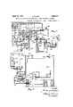
- Fig. 41 is a diagrammatic view illustrating my invention applied to a boiler and furnace in which a fluid fuel is used
- Fig. 5 is a detail View of certain parts of Fig. 4.
- Fig. 6 is a detail view in vertical section through the draft control device, illustrated in Fig. 4
- Fig. 7 is a view similar to Fig.
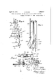
- Fig. 8 is a similar view illustratin my invention in connection with a furnace for burning solid fuel
- Fig. 9 is a sectional view illustrating the adjustment of one of the contacts.
- a pressure regulator illustrated in Fig. 1, in which embodiment the regulator is responsive to steam pressure, 10 1s frame comprising a lower section 1O and an upper section 10", between which is mounted a diaphragm 11 of flexible material. Beneath the diaphragm, a chamber 12 is provided with which communicates a pipe 13 leading to a steam boiler or othersource of fluid pressure. On the diaphragm 11 is mounted a member 14 carrying knife edge 15, engaging a bearing 16, on a lever arm 17, movable to and away from a condition of equilibrium and provided at its inner end with knife edge 18 engaging a bearing 19 on the frame.
- a cylinder 20 mounted with piston 21 and piston stem 22 extending upwardly through a stuffing box 23.
- a pilot valve 24 having an inlet 25, connected to a source of fluid pressure, such, for example, as water under pressure and which communicates with a chamber 26 in the pilot valve.
- the pilot valve is also provided with an'outlet opening 27.
- the chamber 26 communicates with the ends of the cylinder 20 by passages 28 and 29 which, in the arrangement shown,
- a stem 30 Located within the chamber 26 is a stem 30, the lower end of which is pivoted, as at 31, to the lever arm 17 and provided with an upper valve head 32 and a lower valve head 33.
- the upper end of the piston rod 22 is'provided with a laterally extending arm 3 1 to the outer end of which is pivoted at 35, a rod 36, the lower end of which is pivoted at 37 to a lever 38, in turn pivoted at 39 on a bracket 10, rigidly attached to the frame 10.
- a tension spring ll To the opposite end of the lever .38 is connected a tension spring ll, the opposite end of which is adjustably connected by a member 42 to the lever arm 17.
- lever arm 17 preferably carries the usual weight 13, and an intermediate part thereof carries a sliding weight 13
- the lever 17 is preferably connected at 44; to a dash-pot 45 by means of a link 46, pivoted to the piston rod 47, the lower end of which is attached to the piston 48 in the cylinder 49, an adjustable by-pass 50 preferably being provided and communicating with opposite ends of the cylinder which preferably contains a suitable liquid.
- the upward movement of the piston 21 will continue until the tension on the spring 41 is increased an amount sufiicient to bring the lever arm 17 back to its original position, thereby closing the pilot valve.
- the movement of the piston stem 22 through a flexible connection 22 controls the rate of combustion in the furnace (not illustrated), an upward movement of the stem decreasing the rate of combustion and a downward movement thereof increasing the rate of combustion.
- theupward movement of the stem will decrease the rate of combustion which will bring about a reduction in the steam pressure and thereby decrease the force exerted through the diaphragm 11 upon the lever arm 17.
- My invention reverses the foregoing operation, and in accordance with my invention the regulator maintains the highest rate of combustion corresponding with the highest steam pressure, and the lowest rate of combustion corresponding with the lowest steam pressure within the limits of the regulator.
- the lever arm 17 is connected to a device operable in accordance with a function of the load on the boiler.
- a diaphragm 51 is mounted between upper and lower sections 52 and 53 of a housing forming upper and lower chambers.
- the upper chamber communicates, in the form here illustrated, with the pipe 55, which may be the main steam outlet pipe from the boiler, or the air supply pipe, but will hereafter be assumed to be the main steam outlet pipe leading from the boiler, the end of the pipe 54 within the steam pipe being bent in the direction from which the steam is coming.
- the lower chamber beneath the diaphragm communicates by means of a pipe 56 with the steam pipe 55, the end of the pipe 56 being at right angles to the direction of the flow of the steam.
- the two pipes 54 and 56 form what is commonly called a 'Pitot tube, the pipe 54c being subjected to the velocity and static pressures of the flowing steam, while the pipe 56 is subjected only to the static pressure thereof, so that the diaphragm responds to the velocity pressure of the steam.
- the diaphragm 51 is connected to the lever arm 17 by means of a stem 57 passing through a stuffing box 58 in the upper housing 52, a tension spring 59 being connected at its lower end to the stem 58 and its upper end to a secondstem 60, which is con nected to the lever arm 17, preferably through a turn-buckle'61.
- One end of a compression spring 62 engages the lower side of the diaphragm 51 and the lower end thereof is adjustably seated in a cup 63, as illustrated, so that the compression on the spring and the I operation of the diaphragm 51 are adjustable.
- the retarding device shown as a dash-pot 45 serves a useful purpose in givinga slow movement to the lever arm 17, so that the relative effect of a change in steam pressure, compared with the change in tension of the compensating spring 41, will have time to become etlective and will prevent the regulator from making a change in the rate of combustion greater than that due to the change in the load.
- the (-3X- tension member 38 provided with a recess 64, in which is received the right hand end of the lever 38, the two parts being preferably secured together by a set screw 65.
- the (-3X- tension member 38 is provided with a slot 66, in which is received a pin 67 passing through a connecting member 68, preferably in the form of a yoke, having two arms, as illustrated in Fig.
- bracket plate 69 which is also preferably in the form of a yoke memberand adjustably attached to the bracket by means of a lug or flange 70, a bolt 71 passing through the said flange and through a slot 72 in the bracket 40
- the plate or yoke 69 is also provided withaslot 73,through which the connecting pin 67 also passes, and the shape of which will vary the effective distance between the pivotal point 39 of the lever 38 and th attachment of the spring 41 thereto.
- the slot 73 can be given any desired form so that any movement of the piston 21 at any point within its range will produce any desired change in the tension of the
- the slot 73 is curved in such a way that when the lever 38 is in the position illustrated, corresponding to the intermediate position of the piston 21', changes in position of the piston 21 will be accompanied by relatively slight changes in the effective distance between the pivotal point 39 and the pin 67, and consequently in the tension of the spring 41, while changes in position of the piston 21 near the ends of its stroke, and near the end of its range of movement, will bring about relatively great changes in the effective length of the distance between the pivotal point 39 and the pin 67, and consequently in the tension in the spring 41, because as will be evident, when the right hand end of the lever 38 is near theextreme upper or lower positions and the pin in the upper or lowerends of the slot 73, the varia tions in distance of the pin 67 from the pivot 39 will be relatively great, and will bring about relatively reat changes in tension in the spring 41.
- Y I have shown a still further modification of the arrangement illustrated in Fig. 1.
- the lever arm 17 is, or may be, connected to and operated by a diaphragm which is, in turn, operated by steam pressure from the pipe 13.
- a sliding weight 43* is mounted on the lever arm 17 as in Fig. 1.
- An operating rod 74 is pivoted at its lower end to the lever arm 17, and at its upper end is pivoted to one end of a floating lever 75, the other end of which is pivoted at 76 to an arm 77.
- the arm is pivoted at 78 on a bracket 79 on the cylinder 20.
- the stem 30 for the pilot valve 24 is pivoted at its upper end to an intermediate point of the floating lever 75.
- a telescoping connection is provided between the arm 77 and the laterally extending arm 34 which is attached to the upper end of the piston stem 22.
- the telescoping connection' comprises an outer sleeve 81 rigidly attached at its lower end to the arm 77. lVithin the sleeve 81 is received a rod 82, the upper end of which is pivoted, as
- a diaphragm 51 is connected through the spring 59 to the lever arm 17, in the same manner as illustrated in Fig. 1, and need not further be described.
- a spring 85 is attached at one end to an adjustable member 86 on a bracket 87 attached to the frame, while the opposite end thereof is connected to the lever arm 17 The function of the spring 85 is to increase the range of opera tion of the regulator.
- the device shown in Fig. 3 operates in the 3 following manner: Assume a lowering of theload on the boiler and a corresponding increase in pressure beneath the diaphragm 11 (not here shown), the lever arm 17 is raised, thereby raising the rod 74 and the right hand end of the floating lever about 76 as a pivot. The movement of the floating lever raises the piston stem 30 of the pilot valve, thereby admitting fluid pressure to the lower end of the cylinder 20, thereby raising the piston therein and the piston stem 22 to bring about a decrease in the rate of combustion.
- Fig. 4 I have illustrated my invention embodied in a steam boiler and furnace in which fluid fuel is employed.
- the re ulator indicated generally at A, is the same as that described in Fig. 1.
- Fluid fuel is supplied to the furnace by means of a pump 88 which forces fluid fuel through the pipe 89, a valve 90 and a volume regulator 91 to the burner 92 in the furnace.
- the volume regulator 91 is illustrated more in detail in Fig. 5.
- a diaphragm 93 separates the space within the casing in which it is secured into an upper and a lower chamber. Fluid fuel is admitted through the valve 90 and the pipe 89 to the upper chamber 9 1. From the upper chamber the fluid fuel flows through an adjustable passage 95 to the lower chamber 96, and out of the pipe 97 to the burner 92.
- the construction and operation of the regulator 91 is more fully described in my application Serial No. 391,779, which was filed in the Patent Oflice on or about June 25, 1920, to
- an arm 99 pivoted to the frame at 100 The movement of the arm 99 is preferably opposed by an adjustable tension spring 101.
- a flexible member 102 which passes over a grooved pulley 103 on a shaft 104, the end of the flexible member 102 being provided with a weight 105.
- an adjustable cam member 106 which actuates an arm 107 to control the supply of atomizing medium for the fluid fuel.
- The. atomizing medium in the form shown.
- the fuel valve 90 is controlled by the operation of the regulator A, a flexible connection 112 being connected at one end to the upper end of the piston stem 22, and the opposite end thereof being wrapped or wound around a pulley 113, attached to an adjustable cam member 114, which operates an arm 115 pivoted at 116 and actuating the valve 90 in the fluidfuel pipe 89.
- An upward movement of the piston and stem 22 of the regulator A corresponding to a decrease in load and an increase in steam pressure will cause the flexible member 112, which is wrapped around the pulley 113 to rotate the latter clockwise, as viewed in Fig. 5, thereby lowering the arm 115, partially closing the valve 90 and reducing the supply of fluid fuel to the burner.
- the supply of atomizing medium will also be correspondingly varied. It will be evident that the cams 106 and 114 may be adjusted so that for any quantity of fluid fuelflowing to the burner, any desired pressure of atomizing medium may be had.
- a variation in the supply of fluid fuel to the furnace also brings about a change in the draft in the furnace, which controls the air supply.
- this is accomplished through a draft control device, illustrated generally at 117.
- the draft control device which may be the same as that illustrated in my application Serial No. 521,318, which was filed in the Patent Ofiice on or about December 10, 1921, comprises a swinging plate 118 in an opening 119 in the furnace wall, the plate 118 being pivoted at 120 and preferably provided with a counterweight 121, which keeps the plate in neutral equilibrium.
- An arm 122 is secured on the shaft'120 and to the end of the arm is attached an adjustable spring 123.
- a second spring 12% below the arm 120 is also attached thereto,
- the pressure regulator is indicated generally at A, and is, or may be, the same as that illustrated and described in connection with Fig. 1.
- the powdered fuel device comprises a hopper 133 for the powdered fuel which leads to a screw conveyor 134.
- A'blower 135 is connected to the pipe 136 carrying the powdered fuel and forces the same to the burner 137 in the usual way.
- the screw conveyor for the feed is operated by a motor 138 through suitable gearing 139.
- a draft equipment is provided for maintaining in the furnace a desired draft.
- Such equipment comprises a draft control device 117, which may be the same as that described in connection with Fig. 4 and which actuates a damper 131 in the outlet flue, in the same manner as does the draft control device in Fig.4.
- the speed of the motor 138 which feeds the powdered fuel is controlled by the pressure regulatorA.
- a flexible member 140 is connected to the upper end of the piston stem 22 of the control device A, and passes over a pulley 141, and idlers 142 and 143, the end of said member being connected to the lower end of a spring 124 to control the operation of the swinging plate 118 of the draft control device, in the same manner as that illustrated and described in connection with Figs. 4 and 6. .
- a contact arm 145 On the shaft 144, on which the pulley 141 is secured, is mounted a contact arm 145, which is thus moved by the flexible member 140, an upward movement of the piston stem 22 causing a clockwise movement of said arm145 and a downward movement of said stem causing a counterclockwise movement thereof.
- the movement of the arm 145 is utilized to control electrically the operation of the motor which feeds powdered fuel, and to adjust a draft control device.
- the contact arm 145 bridges a segmental contact member 146 and a series of spaced contacts 147 arranged concentrically with the segmental contact 146.
- the con tact member 146 is, in the form shown, electrically connected to one terminal of the secondary 148 of a transformer, the primary 149 of which is connected to line conductors 150
- the contacts 147 are connected by individual conductors (not completely illustrated)ileading to individual contacts 152, which engage a cylinder 153 formed of conducting material, but divided by an insulating member or plate 154 into two parts 153 and 153, as indicated.
- a conductor 155 which leads to one terminal of terminal of the primary 149 of said transformer.
- a conductor 158 which is connected to one terminal of a second relay 159, the terminal of which is connected by the conductor 157 to the primary 148 of said transformer.
- the relays 156 and 159 control a circuit to a reversible motor 160, the current flowing from said line conductors 150 and 151 to said motor in one direction when one relay 156 is energized and in the reverse direction to said motor when the other relay 159 is energized.
- the shaft 161 of the motor is connected through suitable gearing 162 to the shaft 163 of the contact cylinder 153, and in the form shown, is connected through suitable gearing 164 to a shaft 165, provided with a worm 166, en aging a sector 167, on the shaft of which is mounted the movable arm 168 of a rheostat 169, which controls the current from the line conductors 150 and 151 to the motor 138.
- the construction of the contact cylinder 153 and the associated parts are more fully illustrated and described in my application Serial No. 706,278 which was filed in the Patent Oflice on or about April 14, 1924, and to which reference may be made for fuller details.
- Fig. 8 I have illustrated my invention in connection with a steam boiler and furnace, wherein the rate of supply of air to the furnace is utilized to control therate of feed of fuel thereto.
- the furnace for the boiler is equipped with an-underfeed stoker 171 actuated by a motor 172, through a sprocket chain 172, which engages sprockets 17 l-and 175 on the shafts of the motor and the stoker, respectively.
- the air is forced to the stoker through a passage 176 by a blower 177, actuated by a steam engine 178, the steam sup ply pipe 179 of which may be connected to the steam boiler and controlled by a valve 180 through the action of an arm 181.
- the regulator A is, or may be, the same as that illustrated in Figs. 1, 4 and 7', the pipes 5 1 and 56 being connected above and below the diaphragm 51 in the same manner.
- the piston stem 22 of the regulator is connected by a flexible connection 182 passing over idler-s 183 and 18 1 to a pulley (not illustrated) which may bathe same as the pulley 113,
- a cam member 185 which may also be the same as the cam member 11 1 in Fig. 5, and the rotation of which raises or lowers the arm 185 to control the rate of flow of steam to the blower engine, an upward movement of the stem 22 corresponding toan increase in steam pressure, resulting from a decrease in the load on the boiler, causing a partial closing of the valve 180 to decrease the flow of steam to the blower engine, and thereby decrease the rate of supply of air to the furnace.
- a lowering of the stem 22 brings about the reverse operation.
- the device which is operated in response to the flow of air in the passage 17 6 preferably comprises two plates or vanes 186 and 1.87 secured on a shaft 188, the two arms preferably being substantially at right angles to each. other, so that the effective surface acted upon by the current of air is substantially constant.
- On the shaft 188 is also mounted a contact arm 189.
- the contact arm 189 en gages a plurality of stationary contacts 190, which are connected by conductors to conwhich engage a cylinder 153 formed of conducting material and divided by an insulating member or plate 15 1- into two parts 155 and 153 ,.the same as the arrangement illustrated in Fig. 7. T he operation of the cylinder through the motor 160 and the control of the motor 174 is the same as the operation of the motor 160 in Fig. 7 and the control of the motor 138, and will not, therefore, further be described.
- the draft control device 117 acts through the pilot valve 127, the cylinder 128, piston 129 and the flexible member 130, which is attached to the damper 131 in the same manner as 'thearrangement illustrated in and more fully de-v scribed in connection with Figs. 4 and 6.
- the swinging plate 118 is not connected to or af-' fected by any other device as in the case of Fig. 1 where the lower spring 124 is connected to an arm 99 which is controlled by the rate of How of fuel to the furnace.
- the draft device maintains a substantially constant pressure at one point in the furnace chamber.
- the contacts 190 are adjustable in the direction of the move ment of the arm 189. In the illustrated embodiment, this adjustment is secured by the.
- VVhile'I have illustrated herein a regulator operable by a diaphragm subjected to steam pressure, and a member operable by the diaphragm away from and to a condition of equilibrium for controlling the rate of combustion, it is to be understood that my invention is not limited to the particular mechanism illustrated, and that it may be carried out with other devices.
- a Bourdon tube may be utilized which is subjected to steam pressure and the movement of which controls the rate of combustion.
- Such a regulator is illustrated in Patent No. 1,073,025 to Bullock which was issued on'or about September 9, 1913, to which reference may be made.
- I have illustrated the regulator as responsive to steam pressure, it is to be understood thatit may respond to other functions of the steam flowing from the boiler, such as its temperature or rate of flow. 7
- a member operable from a condition of equilibrium in response to variations in a function of the steam from the boiler, mechanism operable in response to the movement of said member for controlling the rate of combustion, means operable by the combustion controlling means tending to return said member to a position of equilibrium, and load responsive'means opposing the return of said member to a position of equilibrium.
- a member operable from a condition of equilibrium in response to variations in steam pressure
- mechanism operable in response to the movement of said member for controlling the rate of combustion
- means operable by the combustion controlling means tending to return said member to a position of equilibrium
- load responsive means opposing the return of said member to a position of equilibrium, the force exerted upon said member by the load responsive means overpowering the combined forces exerted thereon by the means for controlling the rate of combustion and the change in steam pressure.
- a member operable from acondition of equilibrium in response to variations in a function of the steam from the boiler, mechanism operable in response to the movement of said member for controlling the rate of combustion, means operable by the combustion controlling means comprising aspring interposed between said member and said means tending to return said member to a position of equilibrium, and load responsive means opposing. the return of said member to a position of equilibrium.
- a member operable froma condition of equilibrium in respons to variations in a function of the steam from the boiler, mechanism operable in response to the movement of said member for controlling the rate of combustion, means operable by the combustion controlling means tending to return said member to a condition of equilibrium, load responsive means opposing the return of said member to a position of equilibrium, and means for retarding the movement of said member 5.
- a member operable from a condition of equilibrium in response to variations in a function of the steam from the boiler, mechanism operable in response to the movement of said member for controlling the rate of combustiom means operable in response to the movement of said mechanism tending to check its own movement, and load responsive means tending to oppose the checking of the movement of said member.
- a member operable from a condition of equilibrium in response to variations in a function ofthe steam fromthe boiler, mechanism operable in response to the movement of said member for controlling the rate of combustion, means comprising telescoping members operable in response to the movement of said mechanism tending to check its own movement, and load responsive means tending to oppose the checking of'the movement of said member.
- a steam boiler regulator 21. member operable from a condition of equilibrium in response to variations in steam pressure, a floating lever operable in accordance with the movement of said member, a valve device operable by said floating lever, mechanism controlled by said Valve device for controlling the rate of combustion, a pivoted arm connected to said floating lever, telescoping members angularly arranged with respect to the movement of said mechanism, one of which members is connected to said mechanism and the other of which is rigidly attached to said arm, the parts being constructed and arranged to cause said members to move the valve mechanism in a direction to check the movement of said mechanism, and load responsive means operatively afiecting said member.
- a regulator for controlling the rate of feed of fuel to the furnace and thereby controlling the rate of combustion, said regulator being provided with means for maintaining in the boiler a higher pressure than normal corresponding to a higher load than normal and a lower pressure than normal corresponding to a lower load than normal.
- a regulator for controlling the rate of feed of fuel to the furnace and thereby controlling the'rate of combustion, means responsive to variations in the rate of feed of fuel for controlling the rate of air supply to the furnace, said regulator beingprovided'with means for-maintaining in the boiler higher pressure corresponding to higher load than normal and lower pressure for lower load than normal.
- means comprising a steam regulator for varying the rate of combustion, and means associated with said regulator and operable for causing the steam pressure in the boiler to vary in the same direction with the load thereon.
- a member operable from a condition of equilibrium in response to variations in a function of the steam from the boiler means operable in response to the movement of said member for controlling the rate of combustion
- 'means operable from a condition of equilibrium in response to variations 1n a function of the steam from the boiler
- means operable in response to the movement of said member for controlling the rate of combustion means controlled by variations in the flow of steam from the boiler and connected to said member, and associated means cooperating with said member and with the aforesaid means for restoring said member to a condition of equilibrium at a steam pressure higher than the initial steam pressure and corresponding to a load higher than the initial load on the boiler and to restore said member to a condition of equilibrium with a steam pressure lower than the initial steam pressure and corresponding to a load on the boiler lower than the initial load.
- a member operable from a condition of equilibrium in response to variations in a function of the steam from the boiler, means operable in response to the movement of said member for controlling the rate of combustion, means comprising compensating mechanism having a variable adiustment throughout the range of the regulator, means controlled by variations in load on the boiler and connected to said member. and associated means cooperating with said member and with the aforesaid means for restoring said member to a condition of equilibrium at a steam pressure higher than the initial steamv pressure and corresponding to a load higher than the initial load on the boiler and to restore said member to a condition of equilibrium with a steam pressure lower than the initial steam pressure and corresponding to a load on the boiler lower than the initial load.
- a regulator for controlling the rate of feed of fuel to the furnace in accordance with a function of the steam from the boiler and thereby controlling the rate of combustion
- means responsive to boiler pressure for controlling the movement of said regulator
- means responsive to load on the boiler for controlling the movement of said regulator
- the method of operating a steam boiler and its furnace which consists in regulating the rate of combustion and maintaining a predetermined steam pressure higher than the initial steam pressure with an increased load on the boiler and for maintaining a predetermined steam pressure lower than the initial steam pressure with a decreased load on the boiler and in accordance with variations a-function of the steam from the boiler.
Landscapes
- Engineering & Computer Science (AREA)
- Chemical & Material Sciences (AREA)
- Combustion & Propulsion (AREA)
- Mechanical Engineering (AREA)
- General Engineering & Computer Science (AREA)
- Control Of Steam Boilers And Waste-Gas Boilers (AREA)
Description
April 12, 1932. E. M LEAN ,3
METHOD AND APPARATUS FOR REGULATING STEAM PRBSSUREIN BOILERS Original Filed March 17. 1925 4 Sheets-Sheet 1 W foul V vfi/v ATTORNEYS April 12, 1932. E. MOLEAN 1,853,371
METHOD AND APPARATUS FOR REGULA'IING STEAM PRESSURE m somans Original Filed March 1'7, 1925 4 Sheets-Sheet 2 Zya.
v INVENTOR.
BY W wx/ M 2 ATTORNEYS April 12, 1932. E. MOLEAN 1,853,371
METHOD AND APPARATUS FOR REGULATING ST EAM PRESSURE IN BOILERS Original Filed March 17, 1925 4 Sheets-Sheet 3 INVENTOR.
April 12, 1932. E. McLEAN 1,853,371
METHOD AND APPARATUS FOR REGULA'I'ING STEAM PRESSURE IN BOILERS Original Filed March 17. 1925 4 Sheets-Sheet 4 INVENTOR.
BY Wm M x 47 ATTORNEYS Patented Apr. 12, 1932 pairs srArss PATENT orrica EMBURY MGLEAN, OF BROOKLYN, NEW YER-K, ASSIGNOR TO THE ENGINEER COM- PANY, OF NEW YDRK, N. Y., A CGRPORATION OF NEW YORK IEETHQD AND APPARATUS F01; REGULATING STEAL! PRESSURE IN BOILERS Application filed March 17, 1925, Serial No. 16,210. Renewed July 7, 1931.
In its broader aspect my invention more particularly relates to a method and apparatus for regulating steam pressure in a steam boiler, wherein an increase in steam pressure is established with an increase in load on the boiler, and a decrease in steam pressure is established with a decrease in loadon the boiler. i 2
My invention also relates to a novel form f regulator. Other novel features of my invention will appear in the specification and will be more particularly pointed out in the claims.
My invention will best be understood by reference to the accompanying drawings in which Fig. 1 is a view illustrating a pressure regulator embodying my invention; Fig. 2 is a fragmentary View illustrating a modification of the arrangement shown in Fig. 1; Fig. 2 is a sectional View through a portion of Fig. 2, Fig. 3 is a view similar to Fig. 1 illustrating a further modification; Fig. 41 is a diagrammatic view illustrating my invention applied to a boiler and furnace in which a fluid fuel is used; Fig. 5 is a detail View of certain parts of Fig. 4.; Fig. 6 is a detail view in vertical section through the draft control device, illustrated in Fig. 4; Fig. 7 is a view similar to Fig. 4 and illustrating my invention as embodiedin a powdered fuel burning device; Fig. 8 is a similar view illustratin my invention in connection with a furnace for burning solid fuel and Fig. 9 is a sectional view illustrating the adjustment of one of the contacts.
Like reference characters indicate like parts throughout the drawings.
referring now to the pressure regulator illustrated in Fig. 1, in which embodiment the regulator is responsive to steam pressure, 10 1s frame comprising a lower section 1O and an upper section 10", between which is mounted a diaphragm 11 of flexible material. Beneath the diaphragm, a chamber 12 is provided with which communicates a pipe 13 leading to a steam boiler or othersource of fluid pressure. On the diaphragm 11 is mounted a member 14 carrying knife edge 15, engaging a bearing 16, on a lever arm 17, movable to and away from a condition of equilibrium and provided at its inner end with knife edge 18 engaging a bearing 19 on the frame. Mounted on the upper part of the frame 10 is a cylinder 20 provided with piston 21 and piston stem 22 extending upwardly through a stuffing box 23. Mounted on the cylinder 20 is a pilot valve 24 having an inlet 25, connected to a source of fluid pressure, such, for example, as water under pressure and which communicates with a chamber 26 in the pilot valve. The pilot valve is also provided with an'outlet opening 27. The chamber 26 communicates with the ends of the cylinder 20 by passages 28 and 29 which, in the arrangement shown,
cross each other without interconnection, as illustrated. Located within the chamber 26 is a stem 30, the lower end of which is pivoted, as at 31, to the lever arm 17 and provided with an upper valve head 32 and a lower valve head 33. The upper end of the piston rod 22 is'provided with a laterally extending arm 3 1 to the outer end of which is pivoted at 35, a rod 36, the lower end of which is pivoted at 37 to a lever 38, in turn pivoted at 39 on a bracket 10, rigidly attached to the frame 10. To the opposite end of the lever .38 is connected a tension spring ll, the opposite end of which is adjustably connected by a member 42 to the lever arm 17. The
outer end of the lever arm 17 preferably carries the usual weight 13, and an intermediate part thereof carries a sliding weight 13 The lever 17 is preferably connected at 44; to a dash-pot 45 by means of a link 46, pivoted to the piston rod 47, the lower end of which is attached to the piston 48 in the cylinder 49, an adjustable by-pass 50 preferably being provided and communicating with opposite ends of the cylinder which preferably contains a suitable liquid.
lVith the parts previously described, the operation would be as follows: Assume that the device is used in connection with a steam boiler, and that the load on the boiler drops below normal, with the result that there is an increase in boiler pressure. This increase in boiler pressure will raise the diaphragm 11 and correspondingly raise the lever arm 17 from its condition of equilibrium. The upward movement of the lever arm 17 raises the rod 30 and its attached valve member, thereby opening communication between the inlet 25 and the passage 29 which communicates with the lower end of the cylinder 20. The piston 21 is thereby raised and the rod 36 and the left end of the lever 38 are correspondingly raised. The tension on the spring 41 is thereby increased. The upward movement of the piston 21 will continue until the tension on the spring 41 is increased an amount sufiicient to bring the lever arm 17 back to its original position, thereby closing the pilot valve. In the arrangement illustrated, the movement of the piston stem 22 through a flexible connection 22 controls the rate of combustion in the furnace (not illustrated), an upward movement of the stem decreasing the rate of combustion and a downward movement thereof increasing the rate of combustion. Under the conditions previously assumed, that is, with an increased steam pressure and an upward movement of the lever arm 17 and the piston stem 22, theupward movement of the stem will decrease the rate of combustion which will bring about a reduction in the steam pressure and thereby decrease the force exerted through the diaphragm 11 upon the lever arm 17. The decrease in steam pressure and the increase in the tension on the spring 11, therefore, combine to bring the lever arm back to its original position and close the'pilot valve. The piston would at this time remain in the position to which 1t is moved, and the steam pressure would be erate, in general, the same as compensating steam regulators which have hitherto been used and wherein the control of the rate of combustion is inversely as the steam pressure that is, a rise in steam pressure would cause a decrease in the rate of combustion, either by partially closing the damper in anatural draft furnace and reducing the draft, or by reducing the speed of the blower or the supply of air in a forced draft furnace. WVith such an arrangement, the highest rate of combustion is maintained when the steam pressure is lowest and the lowest rate of combustion is maintained when the steam pressure is highest. This means that when the heaviest load of combustion, the steam pressure is at the lowest point, and consequently the steam engine which is being called upon for maximum duty is handicapped by operating at the low-. est steam pressure within the range of the regulator. In order to obviate this difficulty,
it has been common to reduce the limits of regulation of the regulator to a very few pounds boiler pressure. Such an equipment operates fairly well, so far as the steam engine is concerned, but is very unsatisfactory from the standpoint of efiiciency of combustion of the furnace, as slight changes in steam pres sure cause violent changes in the rate of combustion. On the other hand, if the regulator be made to operate over a wide range of pressure, so that slight fluctuations in steam pressure produce correspondingly slight variations in the rate of combustion, the diificulty is encountered that with the maximum load on the engine, the boiler pressure controlled by the regulator is at a minimum.
My invention reverses the foregoing operation, and in accordance with my invention the regulator maintains the highest rate of combustion corresponding with the highest steam pressure, and the lowest rate of combustion corresponding with the lowest steam pressure within the limits of the regulator. In the arrangement illustrated in Fig. 1, the lever arm 17 is connected to a device operable in accordance with a function of the load on the boiler. In the form shown, a diaphragm 51 is mounted between upper and lower sections 52 and 53 of a housing forming upper and lower chambers. The upper chamber communicates, in the form here illustrated, with the pipe 55, which may be the main steam outlet pipe from the boiler, or the air supply pipe, but will hereafter be assumed to be the main steam outlet pipe leading from the boiler, the end of the pipe 54 within the steam pipe being bent in the direction from which the steam is coming. The lower chamber beneath the diaphragm communicates by means of a pipe 56 with the steam pipe 55, the end of the pipe 56 being at right angles to the direction of the flow of the steam. The two pipes 54 and 56 form what is commonly called a 'Pitot tube, the pipe 54c being subjected to the velocity and static pressures of the flowing steam, while the pipe 56 is subjected only to the static pressure thereof, so that the diaphragm responds to the velocity pressure of the steam. The diaphragm 51 is connected to the lever arm 17 by means of a stem 57 passing through a stuffing box 58 in the upper housing 52, a tension spring 59 being connected at its lower end to the stem 58 and its upper end to a secondstem 60, which is con nected to the lever arm 17, preferably through a turn-buckle'61. One end of a compression spring 62 engages the lower side of the diaphragm 51 and the lower end thereof is adjustably seated in a cup 63, as illustrated, so that the compression on the spring and the I operation of the diaphragm 51 are adjustable.
due to the increased rate of flow of steam in the pipe 55, by an increase in pressure above the diaphragm 51. The combined action of these changes would be to lower the lever arm 17 which, acting through the pilot valve 24, would lower the piston 21 and piston rod 22, which action would increase the rate of combustion. At the same time, lowering the arm 34 would cause a reduction in tension on the spring 41, and the piston rod 22 would continue to descend until the decrease in tension on the spring 41 allowed the lever arm 17 to resume its original horizontal position and close the pilot valve 24. Under this condition, the increased steam pressure, due to the increased rate of combustion acting with the decreased tension on the spring 41 and the increased tension on the spring 59 form a balance, but at a higher steam pressure than the initial one which was maintained before the change took place. Conversely, a reduction in load on the boiler would cause initially an increase in pressure of the steam undo the diaphragm 11, and a reduction in pres sure over the diaphragm 51, the combined ac tion of which would cause the lever arm 17 to move upward, operating the pilot valve so that the piston 21 and piston rod 22 move upward, causing a decrease in the rate of combustion. This upward movement operating through the bracket 34 and the connecting mechanism would increase the tension on the spring 41. At the same time, the decreased rate of combustion would cause a reduction in pressure under the diaphragm 11, and the piston rod 22 would move upward, the combined action of these forces bringing the lever arm 17 to its original or horizontal position,
closing the pilot valve 24. When this balance takes place, the steam pressure in the boiler is lower than it was in the original condition. As the element of time is a necessary element in causing the static pressure to respond to a change in rate of combustion,
. the retarding device shown as a dash-pot 45 serves a useful purpose in givinga slow movement to the lever arm 17, so that the relative effect of a change in steam pressure, compared with the change in tension of the compensating spring 41, will have time to become etlective and will prevent the regulator from making a change in the rate of combustion greater than that due to the change in the load.
With an initial reduction in load on the boiler there is a corresponding increase in steam pressure. This acts on the diaphragm 11 and the arm'17 to raise the arm which, in turn, acts on the pilot valve admitting pressure below the piston 21 which raises the piston rod 22, and through the chain 22 reduces the rate of combustion which will tend to re duce the pressure of steam in the boiler. At the same time, the rod 36 moves upward and through the lever 38 increases the tension on the spring 41. The reduction in load on the boiler reduces the flow of steam through the pipe 55, thereby reducing the excess pressure above the diaphragm 51 over that below the diaphragm, and the action of the spring 62 raises the diaphragm, thereby reducing the tension on the spring 59. We now have a lowersteam pressure due to the reduced rate of combustion under the diaphragm 11, and in order to balance the lever arm 17 to bring it to its neutral position, the combined effect of the spring 41 acting through its leverage and the spring 59 acting through its leverage must be less than at the start; therefore, the reduction in tension on t the spring 59 acting through its leverage on the arm17 must be greater than the increase in tension on the spring 41 acting through its leverage. Under these conditions, the arm comes to a balance or neutral position, with a lower steam pressure in the boiler corresponding to a condition of lower load 011 the boiler. it is obvious that an increase in load on the boiler through a reverse operation will pro.- duce a condition of equilibrium with a higher pressure in the boiler, because an increase in load on the boiler is accompanied by a reduction in steam pressure, allowing the arm 17 to move downwardly, which causes the rod 22 through the chain 22 to move downwardly increasing the rate of combustion which tends to increase the pressure on the boiler; At the same time, the downward movement of the rod through the lever 38 decrease the tension on the spring 41 acting through its leverage on the arm, and the increased flow ofsteam from the boiler increases the excess of pressure, above the diaphragm 51 over that below the diaphragm, thereby compressing the spring 62 and increasing the tension on the spring 59. The increased tension on the spring 59 through its leverage on the arm 17 being greater than the decrease of tension on41 through its leverage on the arm will balance the arm with a higher steam pressure below the diaphragm 11 than at the beginning of the operation, thereby producing a higher steam pressure corresponding to a higher load. I
in the arrangement previously described, the variation in tension on the spring 41 produced by variations in load on the boiler are fairly uniform. In Fig. 2, I have shown an arrangement 111 Wl11Cl1 changes 1n steam pressure in the middle of the stroke of the piston 21 and piston stem 22 produce relatively gradual changes in the tension of the spring 41, and changes in the position of the piston rod and stem near the ends of their stroke produce relatively great variations in tension in the spring 41. The lever 38 corresponds with the lever 38 of Fig. 1 and is pivoted at 39. The right hand end of the lever 38 is preferably provided with an ex- 8 spring 41.
In the arrangement lllustrated in Fig. 3,
Y I have shown a still further modification of the arrangement illustrated in Fig. 1. The lever arm 17 is, or may be, connected to and operated by a diaphragm which is, in turn, operated by steam pressure from the pipe 13.
the same as the arrangement shown in Fig. 1, and the results secured by the operation of the device here shown are generally the same as those obtained by the arrangement shown in Fig. 1. A sliding weight 43* is mounted on the lever arm 17 as in Fig. 1. An operating rod 74 is pivoted at its lower end to the lever arm 17, and at its upper end is pivoted to one end of a floating lever 75, the other end of which is pivoted at 76 to an arm 77. The arm is pivoted at 78 on a bracket 79 on the cylinder 20. The stem 30 for the pilot valve 24 is pivoted at its upper end to an intermediate point of the floating lever 75. In the arrangement here shown, a telescoping connection, indicated generally at 80, is provided between the arm 77 and the laterally extending arm 34 which is attached to the upper end of the piston stem 22. The telescoping connection' comprises an outer sleeve 81 rigidly attached at its lower end to the arm 77. lVithin the sleeve 81 is received a rod 82, the upper end of which is pivoted, as
at 83, to a bracket 84, adjustably mounted on the arm 34. A diaphragm 51 is connected through the spring 59 to the lever arm 17, in the same manner as illustrated in Fig. 1, and need not further be described. A spring 85 is attached at one end to an adjustable member 86 on a bracket 87 attached to the frame, while the opposite end thereof is connected to the lever arm 17 The function of the spring 85 is to increase the range of opera tion of the regulator.
The device shown in Fig. 3 operates in the 3 following manner: Assume a lowering of theload on the boiler and a corresponding increase in pressure beneath the diaphragm 11 (not here shown), the lever arm 17 is raised, thereby raising the rod 74 and the right hand end of the floating lever about 76 as a pivot. The movement of the floating lever raises the piston stem 30 of the pilot valve, thereby admitting fluid pressure to the lower end of the cylinder 20, thereby raising the piston therein and the piston stem 22 to bring about a decrease in the rate of combustion.
The upward movement of the piston rod 22 and the arm 34 attached thereto causes the rod 82 to move upwardly within the sleeve 81, which causes the sleeve 81 to turn the arm 77 about the pivot 78 ina clockwise direction, thereby lowering the left hand end of the floating lever 75 about the pivotal connection with the rod 74 and lowering the stem 30 of the pilot valve to close the latter.
The lowering of the rate'of combustion and hence the decrease in flow of steam from the boiler decreases the tension on the spring 59, the tension on the spring having been increased by the upward movement of the lever 17. The proportions and tensions of the springs 59 and 85 are such that the spring 59 predominates over the combined action of the spring 85 and the increased pressure due to load variation, and the regulator is not brought to a condition of equilibrium until the pressure has been reduced to a point below normal, so that the regulator will then be operating at a lower pressure for a lower load than normal. Similarly, the regulator will operate at a higher pressure for a higher load than normal. In the device illustrated in Fig. .1, when the regulator is in a condition of equilibrium, the. member 17 is always returned to the same Josition. In the arrangement illustrated in *ig. 3, on the other hand, the regulator is brought to a position of equilibrium with the member 17 in different positions, the same occupying higher positions than normal for lower loads, and lower positions for higher loads.
In Fig. 4, I have illustrated my invention embodied in a steam boiler and furnace in which fluid fuel is employed. The re ulator, indicated generally at A, is the same as that described in Fig. 1. Fluid fuel is supplied to the furnace by means of a pump 88 which forces fluid fuel through the pipe 89, a valve 90 and a volume regulator 91 to the burner 92 in the furnace. The volume regulator 91 is illustrated more in detail in Fig. 5. A diaphragm 93 separates the space within the casing in which it is secured into an upper and a lower chamber. Fluid fuel is admitted through the valve 90 and the pipe 89 to the upper chamber 9 1. From the upper chamber the fluid fuel flows through an adjustable passage 95 to the lower chamber 96, and out of the pipe 97 to the burner 92. The construction and operation of the regulator 91 is more fully described in my application Serial No. 391,779, which was filed in the Patent Oflice on or about June 25, 1920, to
which reference may be had forfurther details. Briefly, it may be stated that an increase in the rate of flow of fluid fuel through the regulator depresses the diaphragm 93 and a stem 98'wl1ich is connected thereto, and
the upper end of which is connected to an arm 99 pivoted to the frame at 100. The movement of the arm 99 is preferably opposed by an adjustable tension spring 101. To the end of the arm 99 is attached a flexible member 102 which passes over a grooved pulley 103 on a shaft 104, the end of the flexible member 102 being provided with a weight 105. Also secured to the shaft 104: is an adjustable cam member 106 which actuates an arm 107 to control the supply of atomizing medium for the fluid fuel. The. atomizing medium, in the form shown. is steam taken from the steam outlet pipe 55 by means of a pipe 108, through a reducing valve 109, and a valve 110 controlled by the said arm 107 fro-m which valve the atomizing medium is conducted by a pipe 111 to the burner 92.
The fuel valve 90 is controlled by the operation of the regulator A, a flexible connection 112 being connected at one end to the upper end of the piston stem 22, and the opposite end thereof being wrapped or wound around a pulley 113, attached to an adjustable cam member 114, which operates an arm 115 pivoted at 116 and actuating the valve 90 in the fluidfuel pipe 89. An upward movement of the piston and stem 22 of the regulator A, corresponding to a decrease in load and an increase in steam pressure will cause the flexible member 112, which is wrapped around the pulley 113 to rotate the latter clockwise, as viewed in Fig. 5, thereby lowering the arm 115, partially closing the valve 90 and reducing the supply of fluid fuel to the burner. By the connections above described, the supply of atomizing medium will also be correspondingly varied. It will be evident that the cams 106 and 114 may be adjusted so that for any quantity of fluid fuelflowing to the burner, any desired pressure of atomizing medium may be had.
In the arrangement illustrated in Figf l, a variation in the supply of fluid fuel to the furnace also brings about a change in the draft in the furnace, which controls the air supply. In the arrangement shown, this is accomplished through a draft control device, illustrated generally at 117. The draft control device, which may be the same as that illustrated in my application Serial No. 521,318, which was filed in the Patent Ofiice on or about December 10, 1921, comprises a swinging plate 118 in an opening 119 in the furnace wall, the plate 118 being pivoted at 120 and preferably provided with a counterweight 121, which keeps the plate in neutral equilibrium. An arm 122 is secured on the shaft'120 and to the end of the arm is attached an adjustable spring 123. A second spring 12% below the arm 120 is also attached thereto,
the free end of the spring 124 being connected through a flexible member 125, passing over a pulley 126 to the arm 99. The movement of the plate 118 of the draft control device 117 actuates a pilot valve 127 and admits fluid pressure to the lower end of a cylinder 128, the piston 129 of which is connected by a flexible member 130 to the damper 131 by the 391,779 above referred to, and which need not be more fully described. Briefly, however, it may be stated that an inward movement of the plate 118,; that is, a movement of the plate counterclockwise, as viewed in Fig. 6, will move the damper towards the closed position, and a movement in the opposite direction will move the damper toward its open position. The flow of fuel therefore controls the position of the swinging plate and correspondingly controls draft conditions.
In Fig. 7 I have illustrated my invention and 151.
embodied in a powdered fuel burning device. The pressure regulator is indicated generally at A, and is, or may be, the same as that illustrated and described in connection with Fig. 1. In the arrangement illustrated, the powdered fuel device comprises a hopper 133 for the powdered fuel which leads to a screw conveyor 134. A'blower 135 is connected to the pipe 136 carrying the powdered fuel and forces the same to the burner 137 in the usual way. The screw conveyor for the feed is operated by a motor 138 through suitable gearing 139. In the form shown, a draft equipment is provided for maintaining in the furnace a desired draft. Such equipment comprises a draft control device 117, which may be the same as that described in connection with Fig. 4 and which actuates a damper 131 in the outlet flue, in the same manner as does the draft control device in Fig.4.
In the arrangement here illustrated, the speed of the motor 138 which feeds the powdered fuel is controlled by the pressure regulatorA.
In the form illustrated, a flexible member 140 is connected to the upper end of the piston stem 22 of the control device A, and passes over a pulley 141, and idlers 142 and 143, the end of said member being connected to the lower end of a spring 124 to control the operation of the swinging plate 118 of the draft control device, in the same manner as that illustrated and described in connection with Figs. 4 and 6. .On the shaft 144, on which the pulley 141 is secured, is mounted a contact arm 145, which is thus moved by the flexible member 140, an upward movement of the piston stem 22 causing a clockwise movement of said arm145 and a downward movement of said stem causing a counterclockwise movement thereof. In the form shown, the movement of the arm 145 is utilized to control electrically the operation of the motor which feeds powdered fuel, and to adjust a draft control device. The contact arm 145 bridges a segmental contact member 146 and a series of spaced contacts 147 arranged concentrically with the segmental contact 146. The con tact member 146 is, in the form shown, electrically connected to one terminal of the secondary 148 of a transformer, the primary 149 of which is connected to line conductors 150 The contacts 147 are connected by individual conductors (not completely illustrated)ileading to individual contacts 152, which engage a cylinder 153 formed of conducting material, but divided by an insulating member or plate 154 into two parts 153 and 153, as indicated. Connected to one contacting member 153 of said cylinder is a conductor 155 which leads to one terminal of terminal of the primary 149 of said transformer. To the other contacting member 153 of-said cylinder is electrically connected a conductor 158 which is connected to one terminal of a second relay 159, the terminal of which is connected by the conductor 157 to the primary 148 of said transformer. The relays 156 and 159 control a circuit to a reversible motor 160, the current flowing from said line conductors 150 and 151 to said motor in one direction when one relay 156 is energized and in the reverse direction to said motor when the other relay 159 is energized. The shaft 161 of the motor is connected through suitable gearing 162 to the shaft 163 of the contact cylinder 153, and in the form shown, is connected through suitable gearing 164 to a shaft 165, provided with a worm 166, en aging a sector 167, on the shaft of which is mounted the movable arm 168 of a rheostat 169, which controls the current from the line conductors 150 and 151 to the motor 138. The construction of the contact cylinder 153 and the associated parts are more fully illustrated and described in my application Serial No. 706,278 which was filed in the Patent Oflice on or about April 14, 1924, and to which reference may be made for fuller details. The operation of the device illustrated in Fig. 7 is briefly as follows: Assuming that there is an increase in steam pressure in the boiler, the piston stem 22 will move upwardly, thereby rotating the contact arm 145 clockwise. A circuit will thereby be closed through the segmental contact 146 and one of the contact members 147 at the right of the arm 145,
through one of the contacts 152 which engages L the contact cylinder 153 through the segment 153 relay 159 and conductor 157, through the secondary 148 of the transformer to the contact 146. A circuit will thereby be closed through the reversible motor 160 in a given.
direction to rotate the shaft thereof, and through the gearing 162 will rotate the contact cylinder until the contact 152 which has been energized. is brought into engagement with the insulating member 154, whereupon the relay will be de-energized, the circuit .to the motor broken and the motor 160 will stop. At the same time the rotation of the motor 160 through the shaft will operate the rheostat 169 in a direction to cause the controlled motor 138 to decrease in speed to decrease the rate of feed of fuel corresponding to the increase in steam pressure which cause an upward movement in the piston stem 22 and a decrease in load. At the same time the flexibleconnection 146 decreases the tension on the spring 124, thereby causing the movable plate 118 to assume a new position and to decrease the draft corresponding to the decreased rate of fuel feed.
In Fig. 8, I have illustrated my invention in connection with a steam boiler and furnace, wherein the rate of supply of air to the furnace is utilized to control therate of feed of fuel thereto. In the arrangement.illus trated, the furnace for the boiler is equipped with an-underfeed stoker 171 actuated by a motor 172, through a sprocket chain 172, which engages sprockets 17 l-and 175 on the shafts of the motor and the stoker, respectively. The air is forced to the stoker through a passage 176 by a blower 177, actuated by a steam engine 178, the steam sup ply pipe 179 of which may be connected to the steam boiler and controlled by a valve 180 through the action of an arm 181.
The regulator A is, or may be, the same as that illustrated in Figs. 1, 4 and 7', the pipes 5 1 and 56 being connected above and below the diaphragm 51 in the same manner. The piston stem 22 of the regulator is connected by a flexible connection 182 passing over idler- s 183 and 18 1 to a pulley (not illustrated) which may bathe same as the pulley 113,
9 illustrated in Fig. 5, and on the shaft of which is also mounted a cam member 185, which may also be the same as the cam member 11 1 in Fig. 5, and the rotation of which raises or lowers the arm 185 to control the rate of flow of steam to the blower engine, an upward movement of the stem 22 corresponding toan increase in steam pressure, resulting from a decrease in the load on the boiler, causing a partial closing of the valve 180 to decrease the flow of steam to the blower engine, and thereby decrease the rate of supply of air to the furnace. A lowering of the stem 22 brings about the reverse operation.
In the arrangement here illustrated, the variations in the supply of air to the stoker, as stated, are utilized to control the rate of feed of fuel to the furnace. The device which is operated in response to the flow of air in the passage 17 6 preferably comprises two plates or vanes 186 and 1.87 secured on a shaft 188, the two arms preferably being substantially at right angles to each. other, so that the effective surface acted upon by the current of air is substantially constant. On the shaft 188 is also mounted a contact arm 189.
' variations in the rate of feed of fuel to the tacts 152,
furnace by electrical means which are, or may be, substantially the same as those illustrated in my application Serial No. 706,27 above re ferred to, and which will, therefore, be only briefly described. The contact arm 189 en gages a plurality of stationary contacts 190, which are connected by conductors to conwhich engage a cylinder 153 formed of conducting material and divided by an insulating member or plate 15 1- into two parts 155 and 153 ,.the same as the arrangement illustrated in Fig. 7. T he operation of the cylinder through the motor 160 and the control of the motor 174 is the same as the operation of the motor 160 in Fig. 7 and the control of the motor 138, and will not, therefore, further be described. An upward movement of the piston stem 22 corresponding to an increase in steam pressure and a decrease in load on the boiler, causes a decrease in the rate of air supplied to the furnace, and through the connection of the plates 186 and 187 and the electrical equipment responding to the movement of said plates, the rate of feed of fuel is lowered. On the other hand, a decrease in steam pressure on the steam boilerresulting from an increase in load will increase the rate of air supplied to the furnace, and the movement of the plates 186 and 187 in response thereto will bring about an increase in the rate of feed of fuel.
In the arrangement here shown, the draft control device 117 acts through the pilot valve 127, the cylinder 128, piston 129 and the flexible member 130, which is attached to the damper 131 in the same manner as 'thearrangement illustrated in and more fully de-v scribed in connection with Figs. 4 and 6. In the arrangement here shown, however, the swinging plate 118 is not connected to or af-' fected by any other device as in the case of Fig. 1 where the lower spring 124 is connected to an arm 99 which is controlled by the rate of How of fuel to the furnace. In the arrangement here shown, the draft device maintains a substantially constant pressure at one point in the furnace chamber. In the device illustrated in Fig. 8, the contacts 190 are adjustable in the direction of the move ment of the arm 189. In the illustrated embodiment, this adjustment is secured by the.
provision of a slot 191 for each contact in the base piece 192 in which the contacts are tion along the slots 191, so that for any given rate of air supply to the furnace, any desired rate of feed of fuel thereto may be secured. In the form of my invention illustrated in r Fig. 8, as in all of the forms, it is understood that a higher pressure than normal is pro-, duced corresponding to a higher load than normal, and a lower pressure than normal corresponding to a lower load than normal.
VVhile'I have illustrated herein a regulator operable by a diaphragm subjected to steam pressure, and a member operable by the diaphragm away from and to a condition of equilibrium for controlling the rate of combustion, it is to be understood that my invention is not limited to the particular mechanism illustrated, and that it may be carried out with other devices. For example, a Bourdon tube may be utilized which is subjected to steam pressure and the movement of which controls the rate of combustion. Such a regulator is illustrated in Patent No. 1,073,025 to Bullock which was issued on'or about September 9, 1913, to which reference may be made. Furthermore, while I have illustrated the regulator as responsive to steam pressure, it is to be understood thatit may respond to other functions of the steam flowing from the boiler, such as its temperature or rate of flow. 7
It is obvious that my invention is applicable to forms of regulators other than that specifically described in the application.
I claim:
1. In a steam boiler regulator, a member operable from a condition of equilibrium in response to variations in a function of the steam from the boiler, mechanism operable in response to the movement of said member for controlling the rate of combustion, means operable by the combustion controlling means tending to return said member to a position of equilibrium, and load responsive'means opposing the return of said member to a position of equilibrium.
2. In a steam boiler regulator, a member operable from a condition of equilibrium in response to variations in steam pressure, mechanism operable in response to the movement of said member for controlling the rate of combustion, means operable by the combustion controlling means tending to return said member to a position of equilibrium, and load responsive means opposing the return of said member to a position of equilibrium, the force exerted upon said member by the load responsive means overpowering the combined forces exerted thereon by the means for controlling the rate of combustion and the change in steam pressure.
3. In a steam boiler regulator, a member operable from acondition of equilibrium in response to variations in a function of the steam from the boiler, mechanism operable in response to the movement of said member for controlling the rate of combustion, means operable by the combustion controlling means comprising aspring interposed between said member and said means tending to return said member to a position of equilibrium, and load responsive means opposing. the return of said member to a position of equilibrium.
l. In a steam boiler regulator, a member operable froma condition of equilibrium in respons to variations in a function of the steam from the boiler, mechanism operable in response to the movement of said member for controlling the rate of combustion, means operable by the combustion controlling means tending to return said member to a condition of equilibrium, load responsive means opposing the return of said member to a position of equilibrium, and means for retarding the movement of said member 5. In a steam boiler regulator, a member operable from a condition of equilibrium in response to variations in a function of the steam from the boiler, mechanism operable in response to the movement of said member for controlling the rate of combustiom means operable in response to the movement of said mechanism tending to check its own movement, and load responsive means tending to oppose the checking of the movement of said member.
6. Ina'ste am boiler regulator, a member operable from a condition of equilibrium in response to variations in a function ofthe steam fromthe boiler, mechanism operable in response to the movement of said member for controlling the rate of combustion, means comprising telescoping members operable in response to the movement of said mechanism tending to check its own movement, and load responsive means tending to oppose the checking of'the movement of said member.
7. In a steam boiler regulator, 21. member operable from a condition of equilibrium in response to variations in steam pressure, a floating lever operable in accordance with the movement of said member, a valve device operable by said floating lever, mechanism controlled by said Valve device for controlling the rate of combustion, a pivoted arm connected to said floating lever, telescoping members angularly arranged with respect to the movement of said mechanism, one of which members is connected to said mechanism and the other of which is rigidly attached to said arm, the parts being constructed and arranged to cause said members to move the valve mechanism in a direction to check the movement of said mechanism, and load responsive means operatively afiecting said member.
8. In a steam boiler and its furnace, means for feeding fuel to the furnace, a regulator for controlling the rate of feed of fuel to the furnace and thereby controlling the rate of combustion, said regulator being provided with means for maintaining in the boiler a higher pressure than normal corresponding to a higher load than normal and a lower pressure than normal corresponding to a lower load than normal.
9. In a steam boiler and its furnace, means for feeding fuel to the furnace, a regulator for controlling the rate of feed of fuel to the furnace and thereby controlling the'rate of combustion, means responsive to variations in the rate of feed of fuel for controlling the rate of air supply to the furnace, said regulator beingprovided'with means for-maintaining in the boiler higher pressure corresponding to higher load than normal and lower pressure for lower load than normal.
10. In a steam boiler and its furnace, means comprising a steam regulator for varying the rate of combustion, and means associated with said regulator and operable for causing the steam pressure in the boiler to vary in the same direction with the load thereon.
11. In a steam boiler regulator, a member operable from a condition of equilibrium in response to variations in a function of the steam from the boiler, means operable in response to the movement of said member for controlling the rate of combustion, 'means operable from a condition of equilibrium in response to variations 1n a function of the steam from the boiler, means operable in response to the movement of said member for controlling the rate of combustion, means controlled by variations in the flow of steam from the boiler and connected to said member, and associated means cooperating with said member and with the aforesaid means for restoring said member to a condition of equilibrium at a steam pressure higher than the initial steam pressure and corresponding to a load higher than the initial load on the boiler and to restore said member to a condition of equilibrium with a steam pressure lower than the initial steam pressure and corresponding to a load on the boiler lower than the initial load.
13. In a steam boiler regulator, a member operable from a condition of equilibrium in response to variations in a function of the steam from the boiler, means operable in response to the movement of said member for controlling the rate of combustion, means comprising compensating mechanism having a variable adiustment throughout the range of the regulator, means controlled by variations in load on the boiler and connected to said member. and associated means cooperating with said member and with the aforesaid means for restoring said member to a condition of equilibrium at a steam pressure higher than the initial steamv pressure and corresponding to a load higher than the initial load on the boiler and to restore said member to a condition of equilibrium with a steam pressure lower than the initial steam pressure and corresponding to a load on the boiler lower than the initial load.
14. In a steam boiler and its furnace, means for feeding fluid fuel to the furnace. a regulator for controlling the rate of feed of fuel to the furnace in accordance with a function of the steam from the boiler and thereby controlling the rate of combustion, means responsive to boiler pressure for controlling the movement of said regulator, means responsive to load on the boiler for controlling the movement of said regulator, and associated. means cooperating with said member and with the aforesaid means for restoring said 55 member to a condition of equilibrium at a steam pressure higher than the initial steam pressure and corresponding to a load higher than the initial load and to restore said member to a condition of equilibrium with a steam pressure lower than the initial steam pressure and corresponding to a load on the boiler lower than the initial load.
15. The method of operating a steam boiler and its furnace, which consists in regulating the rate of combustion and maintaining a predetermined steam pressure higher than the initial steam pressure with an increased load on the boiler and for maintaining a predetermined steam pressure lower than the initial steam pressure with a decreased load on the boiler and in accordance with variations a-function of the steam from the boiler.
E MBURY MoLEAN.
Priority Applications (1)
| Application Number | Priority Date | Filing Date | Title |
|---|---|---|---|
| US16210A US1853371A (en) | 1925-03-17 | 1925-03-17 | Method and apparatus for regulating steam pressure in boilers |
Applications Claiming Priority (1)
| Application Number | Priority Date | Filing Date | Title |
|---|---|---|---|
| US16210A US1853371A (en) | 1925-03-17 | 1925-03-17 | Method and apparatus for regulating steam pressure in boilers |
Publications (1)
| Publication Number | Publication Date |
|---|---|
| US1853371A true US1853371A (en) | 1932-04-12 |
Family
ID=21775951
Family Applications (1)
| Application Number | Title | Priority Date | Filing Date |
|---|---|---|---|
| US16210A Expired - Lifetime US1853371A (en) | 1925-03-17 | 1925-03-17 | Method and apparatus for regulating steam pressure in boilers |
Country Status (1)
| Country | Link |
|---|---|
| US (1) | US1853371A (en) |
Cited By (3)
| Publication number | Priority date | Publication date | Assignee | Title |
|---|---|---|---|---|
| US2468535A (en) * | 1949-04-26 | Control system for steam boiler | ||
| US2660378A (en) * | 1950-07-08 | 1953-11-24 | Republic Flow Meters Co | Boiler control apparatus |
| WO1986002141A1 (en) * | 1984-09-28 | 1986-04-10 | Vapor Corporation | Combustion and feedwater controller for a flash boiler |
-
1925
- 1925-03-17 US US16210A patent/US1853371A/en not_active Expired - Lifetime
Cited By (3)
| Publication number | Priority date | Publication date | Assignee | Title |
|---|---|---|---|---|
| US2468535A (en) * | 1949-04-26 | Control system for steam boiler | ||
| US2660378A (en) * | 1950-07-08 | 1953-11-24 | Republic Flow Meters Co | Boiler control apparatus |
| WO1986002141A1 (en) * | 1984-09-28 | 1986-04-10 | Vapor Corporation | Combustion and feedwater controller for a flash boiler |
Similar Documents
| Publication | Publication Date | Title |
|---|---|---|
| US2243944A (en) | Combustion control system | |
| US1853371A (en) | Method and apparatus for regulating steam pressure in boilers | |
| US1666270A (en) | Compensation for regulation | |
| US1863406A (en) | Governing mechanism for turbine driven pumps | |
| US1533767A (en) | Governor | |
| US2202218A (en) | Control apparatus | |
| US1619351A (en) | Fluid-pressure-operated regulator | |
| US1680026A (en) | Method and apparatus for controlling furnaces | |
| US1693273A (en) | Pressure regulator | |
| US2205494A (en) | Combustion control system fob | |
| US2212210A (en) | Balanced valve | |
| US2249508A (en) | Hydraulic governing mechanism | |
| US1655681A (en) | Governing mechanism | |
| US2253963A (en) | Governing mechanism | |
| US1854922A (en) | Control apparatus | |
| US1563988A (en) | Pressure-controlled regulating means for furnaces | |
| US3703183A (en) | Turbine speed control | |
| US1707955A (en) | Fluid-pressure regulator | |
| US1814630A (en) | Governor | |
| US2315665A (en) | Feed water control system for boiler furnaces | |
| US1919281A (en) | Regulating means | |
| US1572277A (en) | Automatic draft regulator for furnaces | |
| US1576153A (en) | Governing mechanism for prime movers | |
| US962100A (en) | Pressure-governor. | |
| US2027942A (en) | Combustion control means |