US1853368A - Air compressor - Google Patents
Air compressor Download PDFInfo
- Publication number
- US1853368A US1853368A US394116A US39411629A US1853368A US 1853368 A US1853368 A US 1853368A US 394116 A US394116 A US 394116A US 39411629 A US39411629 A US 39411629A US 1853368 A US1853368 A US 1853368A
- Authority
- US
- United States
- Prior art keywords
- air
- manifold
- reservoir
- support
- compressor
- Prior art date
- Legal status (The legal status is an assumption and is not a legal conclusion. Google has not performed a legal analysis and makes no representation as to the accuracy of the status listed.)
- Expired - Lifetime
Links
- 238000010276 construction Methods 0.000 description 1
- 238000001816 cooling Methods 0.000 description 1
- 239000012530 fluid Substances 0.000 description 1
- 210000002445 nipple Anatomy 0.000 description 1
- 230000000284 resting effect Effects 0.000 description 1
Images
Classifications
-
- F—MECHANICAL ENGINEERING; LIGHTING; HEATING; WEAPONS; BLASTING
- F04—POSITIVE - DISPLACEMENT MACHINES FOR LIQUIDS; PUMPS FOR LIQUIDS OR ELASTIC FLUIDS
- F04B—POSITIVE-DISPLACEMENT MACHINES FOR LIQUIDS; PUMPS
- F04B35/00—Piston pumps specially adapted for elastic fluids and characterised by the driving means to their working members, or by combination with, or adaptation to, specific driving engines or motors, not otherwise provided for
- F04B35/06—Mobile combinations
-
- F—MECHANICAL ENGINEERING; LIGHTING; HEATING; WEAPONS; BLASTING
- F04—POSITIVE - DISPLACEMENT MACHINES FOR LIQUIDS; PUMPS FOR LIQUIDS OR ELASTIC FLUIDS
- F04B—POSITIVE-DISPLACEMENT MACHINES FOR LIQUIDS; PUMPS
- F04B39/00—Component parts, details, or accessories, of pumps or pumping systems specially adapted for elastic fluids, not otherwise provided for in, or of interest apart from, groups F04B25/00 - F04B37/00
- F04B39/06—Cooling; Heating; Prevention of freezing
Definitions
- This invention relates to air or gas compressors, more particularly of the portable type.
- the object is to provide means for securing a more effective cooling of the air prior to its passage to the tools operated thereby.
- Figure 1 is a side view of a standard type of portable compressor showing the improvement in place thereon.
- Figure 2 is a view in elevation and partly in section of the combination cooler and manifold.
- a wheeled support or frame 4 is employed on which is a housing or casing 5 containing the usual aircompressingmechanism.
- Thecompressor is shown at 6 and may be of any well known character.
- the frame at extends at one end beyond the casing 5 and supports a reservoir or container 7 for the air compressed by the compressor 6.
- a suitable pipe 8 therefore connects the compressor 6 and reservoir 7
- This support 9 is extended and provided with a seat for a combined cooler and manifold.
- the cooler or manifold is of tubular form with cylindrical side walls that are corrugated as shown at 11.
- a connection 12 at one end is in communication with one end of the reser voir 7 and thus air is supplied to the manifold.
- Said manifold is furthermore provided with a plurality of outlet nipples 13 that are internally threaded or otherwise formed to permit the attachment thereto of hose lines leading to the tools to be operated With this construction the air in the reservoir 7 even though it has been pro-cooled, is further cooled when it is transmitted from the reservoir to the tools inasmuch as it must Figure 3 1s a cross sectional 3-3 of Figpassthrough the manifold, the corrugations of which constitute means for radiating the heat of the air passing therethrough.
- WhatI'claim is: I -'1.
- The? combination with a supporting frame, of a compressor fmounted thereon, a reservoir for the compressed air mounted transversely on one end of the frame, a manifold body of tubular form mounted on the reservoir and having heat-radiating means, said body having communication with the reservoir, and means for attaching a plurality of hose lines to the body.
Landscapes
- Engineering & Computer Science (AREA)
- Mechanical Engineering (AREA)
- General Engineering & Computer Science (AREA)
- Compressor (AREA)
Description
April 12, 1932. f acF p 1,853,368
AIR COMPRESSOR Filed Sept. 20, 1929 Q-ply z.
Patented Apr. 12, 1932 STATES GEORGE :r. MACFADDEN, 0E QUINCY, ILLINOIsIAS IGNo ro.GAR ER-1JEi\ivEit COM- PANY, or DENVER, COLORADO, A CORPORATION-10F DELAWARE L AIR CbMPRESSOR Application filed September 20, 1929. Serial No. 394,116.-
This invention relates to air or gas compressors, more particularly of the portable type. The object is to provide means for securing a more effective cooling of the air prior to its passage to the tools operated thereby.
The preferred embodiment of the invention is illustrated in the accompanying drawings, wherein:
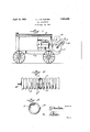
Figure 1 is a side view of a standard type of portable compressor showing the improvement in place thereon.
Figure 2 is a view in elevation and partly in section of the combination cooler and manifold.
In the embodiment disclosed a wheeled support or frame 4 is employed on which is a housing or casing 5 containing the usual aircompressingmechanism. Thecompressor is shown at 6 and may be of any well known character. The frame at extends at one end beyond the casing 5 and supports a reservoir or container 7 for the air compressed by the compressor 6. A suitable pipe 8 therefore connects the compressor 6 and reservoir 7 On the compressor reservoir 7, which is ordinarily a transversely arranged tank, is located a suitable support 9 which carries the gasoline tank 10 that supplies motive fluid to the engine of the compressor. This support 9 is extended and provided with a seat for a combined cooler and manifold. As shown particularly in Figures 2 and 3 the cooler or manifold is of tubular form with cylindrical side walls that are corrugated as shown at 11. A connection 12 at one end is in communication with one end of the reser voir 7 and thus air is supplied to the manifold. Said manifold is furthermore provided with a plurality of outlet nipples 13 that are internally threaded or otherwise formed to permit the attachment thereto of hose lines leading to the tools to be operated With this construction the air in the reservoir 7 even though it has been pro-cooled, is further cooled when it is transmitted from the reservoir to the tools inasmuch as it must Figure 3 1s a cross sectional 3-3 of Figpassthrough the manifold, the corrugations of which constitute means for radiating the heat of the air passing therethrough.
WhatI'claim, is: I -'1. The? combination with a supporting frame, of a compressor fmounted thereon, a reservoir for the compressed air mounted transversely on one end of the frame, a manifold body of tubular form mounted on the reservoir and having heat-radiating means, said body having communication with the reservoir, and means for attaching a plurality of hose lines to the body.
2. The combination with a support, of a compressor and a reservoir for the compressed air mounted on the support, means i for supplying the compressed air in a reservow to a tool, said means including an air cooled manifold through which the air passes to the tool, said manifold being mounted on the support and having connections with the reservoir to receive air therefrom, and said manifold having means for connecting a plurality of tool supply conduits thereto.
3. The combination with a support, of a compressor and a reservoir for the compressed air mounted on the support, means for supplying the compressed air in the reservoir to a tool, said means including an air cooled manifold through which the air passes to the tool, said manifold being mounted on the support and having connections with the reservoir to receive air therefrom, said manifold having heat dissipating means, and said manifold having means for connecting a plurality of tool supply conduits thereto.
4. The combination with a support, of a compressor and a reservoir for the compressed air mounted on the support, means for supplying the compressed air in the reservoir to a tool, said means including an air cooled manifold through which the air passes to the tool, said manifold being mounted on supports resting upon said reservoir and having connections with the latter to receive air therefrom, and said manifold having-means for connecting a plurality of tool supply conduits thereto.
5. The combination with a support, of a compressor and a reservoir for the commounted on the support,means forsupplying air from the receiver to a tool, said means including an air cooled manifold mounted horizontally upon the receiver, and [said manifolddiavingimeans for connecting there'- to a supply conduit leading lto-iatool.
In testimony whereof I ,rafiix my signature.
GEORGE .MACFADDEN.
Priority Applications (1)
| Application Number | Priority Date | Filing Date | Title |
|---|---|---|---|
| US394116A US1853368A (en) | 1929-09-20 | 1929-09-20 | Air compressor |
Applications Claiming Priority (1)
| Application Number | Priority Date | Filing Date | Title |
|---|---|---|---|
| US394116A US1853368A (en) | 1929-09-20 | 1929-09-20 | Air compressor |
Publications (1)
| Publication Number | Publication Date |
|---|---|
| US1853368A true US1853368A (en) | 1932-04-12 |
Family
ID=23557615
Family Applications (1)
| Application Number | Title | Priority Date | Filing Date |
|---|---|---|---|
| US394116A Expired - Lifetime US1853368A (en) | 1929-09-20 | 1929-09-20 | Air compressor |
Country Status (1)
| Country | Link |
|---|---|
| US (1) | US1853368A (en) |
Cited By (1)
| Publication number | Priority date | Publication date | Assignee | Title |
|---|---|---|---|---|
| US3977815A (en) * | 1974-04-24 | 1976-08-31 | Stull James C | Portable apparatus for compressing gases such as air |
-
1929
- 1929-09-20 US US394116A patent/US1853368A/en not_active Expired - Lifetime
Cited By (1)
| Publication number | Priority date | Publication date | Assignee | Title |
|---|---|---|---|---|
| US3977815A (en) * | 1974-04-24 | 1976-08-31 | Stull James C | Portable apparatus for compressing gases such as air |
Similar Documents
| Publication | Publication Date | Title |
|---|---|---|
| US9932799B2 (en) | Tractor and high pressure nitrogen pumping unit | |
| US1853368A (en) | Air compressor | |
| US2118884A (en) | Heating and cooling system for trailer vehicles | |
| US20170022992A1 (en) | Pump shelter | |
| CN211969622U (en) | Fracturing trailer | |
| US1897164A (en) | Liquefied gas distributor's servicing truck | |
| US2216670A (en) | Floor for automobiles | |
| US20130049402A1 (en) | Utilities Pod for Caravans | |
| US1794900A (en) | Tire-inflating mechanism | |
| US2172882A (en) | Antifreeze system | |
| US3108633A (en) | Deaerating heat-engine cooling system | |
| JP4697654B2 (en) | Auxiliary mounting structure for fuel cell vehicles | |
| US20050072553A1 (en) | Gen set with external oil filter and pump | |
| US2455401A (en) | Refrigerating unit for vehicles | |
| US2432755A (en) | Vehicle cooler | |
| US1109193A (en) | Aerating apparatus. | |
| CN211314731U (en) | Hydraulic power station | |
| CN214932615U (en) | Vehicle-mounted liquid tank and fire engine | |
| CN201963388U (en) | Truck engine cooling device | |
| CN214138490U (en) | Brake booster assembly of electronic vacuum pump | |
| CN220180561U (en) | Storage bottle system and heavy vehicle | |
| US2517156A (en) | Evaporative cooler | |
| RU2824234C1 (en) | Mobile pump unit | |
| US1509180A (en) | Lubricating system | |
| US1325318A (en) | Fuel supply system for automobiles |