US1853363A - Base for plastic materials - Google Patents
Base for plastic materials Download PDFInfo
- Publication number
- US1853363A US1853363A US193451A US19345127A US1853363A US 1853363 A US1853363 A US 1853363A US 193451 A US193451 A US 193451A US 19345127 A US19345127 A US 19345127A US 1853363 A US1853363 A US 1853363A
- Authority
- US
- United States
- Prior art keywords
- backing
- fabric
- base
- securing
- plastic material
- Prior art date
- Legal status (The legal status is an assumption and is not a legal conclusion. Google has not performed a legal analysis and makes no representation as to the accuracy of the status listed.)
- Expired - Lifetime
Links
- 239000000463 material Substances 0.000 title description 52
- 239000004744 fabric Substances 0.000 description 66
- 238000010276 construction Methods 0.000 description 8
- 239000002184 metal Substances 0.000 description 3
- 238000000034 method Methods 0.000 description 3
- 239000004568 cement Substances 0.000 description 2
- 230000003247 decreasing effect Effects 0.000 description 2
- 238000004079 fireproofing Methods 0.000 description 2
- 238000004519 manufacturing process Methods 0.000 description 2
- 239000011505 plaster Substances 0.000 description 2
- 238000002360 preparation method Methods 0.000 description 2
- 238000004078 waterproofing Methods 0.000 description 2
- 238000009941 weaving Methods 0.000 description 2
- 238000003466 welding Methods 0.000 description 2
- 239000002023 wood Substances 0.000 description 2
- ATJFFYVFTNAWJD-UHFFFAOYSA-N Tin Chemical compound [Sn] ATJFFYVFTNAWJD-UHFFFAOYSA-N 0.000 description 1
- 229960001948 caffeine Drugs 0.000 description 1
- 238000005336 cracking Methods 0.000 description 1
- 238000002788 crimping Methods 0.000 description 1
- 238000005520 cutting process Methods 0.000 description 1
- 230000003292 diminished effect Effects 0.000 description 1
- 238000001035 drying Methods 0.000 description 1
- 239000000835 fiber Substances 0.000 description 1
- 238000009432 framing Methods 0.000 description 1
- 238000009413 insulation Methods 0.000 description 1
- 235000015250 liver sausages Nutrition 0.000 description 1
- 230000004048 modification Effects 0.000 description 1
- 238000012986 modification Methods 0.000 description 1
- 239000000123 paper Substances 0.000 description 1
- 238000003825 pressing Methods 0.000 description 1
- 239000002994 raw material Substances 0.000 description 1
- 230000002787 reinforcement Effects 0.000 description 1
- 230000003014 reinforcing effect Effects 0.000 description 1
- XYSQXZCMOLNHOI-UHFFFAOYSA-N s-[2-[[4-(acetylsulfamoyl)phenyl]carbamoyl]phenyl] 5-pyridin-1-ium-1-ylpentanethioate;bromide Chemical compound [Br-].C1=CC(S(=O)(=O)NC(=O)C)=CC=C1NC(=O)C1=CC=CC=C1SC(=O)CCCC[N+]1=CC=CC=C1 XYSQXZCMOLNHOI-UHFFFAOYSA-N 0.000 description 1
- 239000007787 solid Substances 0.000 description 1
- RYYVLZVUVIJVGH-UHFFFAOYSA-N trimethylxanthine Natural products CN1C(=O)N(C)C(=O)C2=C1N=CN2C RYYVLZVUVIJVGH-UHFFFAOYSA-N 0.000 description 1
Images

Classifications
-
- E—FIXED CONSTRUCTIONS
- E04—BUILDING
- E04F—FINISHING WORK ON BUILDINGS, e.g. STAIRS, FLOORS
- E04F13/00—Coverings or linings, e.g. for walls or ceilings
- E04F13/02—Coverings or linings, e.g. for walls or ceilings of plastic materials hardening after applying, e.g. plaster
- E04F13/04—Bases for plaster
Definitions
- My invention relates to bases for plastic materials and more particularly to a method and apparatus for securinga backing sheet of metal, Wood, paper or other material to a reticulated metallic fabric of perforated, Woven, Welded or other construction.
- Bases forplastic materials are principally for the purpose of retaining, reinforcing, or acting as a form for plastic materials, and incidental- 1y toprovide fireproofing, sound-deadening, Waterproofing, insulation, or other desirable qualities thereby reducing manufacturing and construction costs and/or providing better construction.
- My invention also provides a backing or form for floors, thereby eliminat ingthe necessity for pans, domes, shoring feathering, dropping or other expedients nee essary with ordinarv methods.
- reticulated metallic fabric such as Woven wire or metallic lath is frequently employed to retain and /or to reinforce the plastic materialduring the time it is hardening and/or to strengthen it after it has hardened.
- a backing often is provided for furnishing a] surface to which plastic material readily adheres vvhile in the plastic state for determining the thickness of the applied plastic material While yet in its plastic state and/or at the same time furnishing fireproofing, sound-deadening, Waterproofing, insulating and /or other qualities.
- the pressure'of'the backing tends to prevent cracking after the material has hardened.
- various expedients have heretofore been employed, such as Weaving Wires, back and forth through. the backing and over the strands or through the openings or perforations in the fabric or metal lath, cutting openings in the backing, and passing the upturned edge of the fastening device therethrough, etc.
- I provide a fastening means for securing the backing and fabric that-is characterized by the use of individual fasteners, each of which is provided ⁇ vitha shank portionthat extends through a single closely fitting opening in the backing; The size of the openings are such that they do not materially impair the strength of the backing and furthermore permit littleif any of the plastic material to pass thercthrough.
- the individual fasteners are preferably provided with a large head that is disposed on the face ofthe backing remote from the fabric and are pressed through the backing and extendthrough a sufiicient distance to engage the strands of the fabric.
- the depth or thickness of the plasticmaterial beneath the fabric may be varied by increasing or decreasing the length of'the fastener shank.
- the outer ends of the individual fasteners are preferably bent or clenched over the strands of the fabric
- the individual fasteners be made hollovv in order that tie Wires can be passed therethrough for tying or fastening the base for plastic materials to beams, columns and the like.
- Base for plastic materials is taken in the usual sense in which it is used in the building and construction which such plastic material is directly applied and which acts as a retainer, reinforcement, and/or form during and after the drying or curing state of such plastic materials.
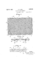
- Figure 1 is a plan View of a retainer for plastic material embodying my invention
- Figure 2 is a View, partially in elevation and partially in section, taken along the section line II-II of Figure 1;
- Figure 3 is a view taken along the section line IIIIII of Figure 1;
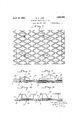
- Figure 4 is a view, similar to Figure 2, showing the retainer after the plastic material has been applied;
- Figure 5 is a view similar to Figurel, showing the application of my invention to metallic lathing
- FIG. 6 is a View, similar to Figure 1, showing the use of a hollow fastening means
- Figure 7 is a plan View showing the application to metallic lathing of the fasteners shown in Figure 6;
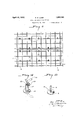
- Figures 8, 9, 10 and 11 are views showing the application of tie wires for securing my retainer to different forms of supporting members; p p
- Figure 12 is a perspective view of a hollow fastener
- Figure 13 is a sectional view showing the application of my invention to metallic studding, joists, beams, girders, angles, channels, or other wood or metal lumber framing and other similar construction.
- Figure .14 is a view showing a modification of my invention in which the base is supported by metallic stands;
- Figure 15 is a perspective view of a solid fastener.
- a reticulated metallic fabric 2 that is constituted of a number of cross strands 5 and 6 of wire that are secured at their points of intersection'by welding and sheet backing 7, preferably of commercial forms of paper or other materials.
- the area of the backing 7 can be less than the area of the metallic fabric 2 in order that the ends and sides of adjacent fabrics 2 may be overlapped to provide strong joints without unnecessarily overlapping the backings 7.
- each fastener comprises a large head 9 and a shank 10 that may be bent around either of the cross wires 5 or 6 and/or welded thereto, as is shown in Figures 2, 3 and 4.
- the fasteners 8 are preferably forced through the backing 7 in order that the openings made therein shall be close- 1y fitting to the shanks 10.
- the strength of the backin 7 is not materially diminished.
- the depth of the plastic material 11 between the fabric 2 and the backing 7 may be varied by increasing or decreasing the length of the shanks 10.
- a modified fastener 17 that is provided with a headlS, a shank l9 and a lip 20.
- longitudinally disposed opening 21 extends through the shank 19 and head 18 for the reception of a tie wire 2-2 or a nail. If a nail is driven through the shank, the fabric and backing will still be spaced the length of the shank 19, and not be brought together as may happen when an ordinary nail is used to secure the base.
- the hollow shank 19 is passed through the backing 7 and the lip 20 is turned over the cross wires 5 or 6 or the lath 14, in accordance with the type of fabric being employed.
- a fabric 2 may be supported by metallic strands by fasteners 31, the ends 32 of which may be secured, as by welding or by crimping, or by both, to the strand 30 and the fabric 2.
- a base for plastic materials characterized by the use of standard reticulated fabric and standard commercial backing material Without subjecting either of them to further preparation.
- the fabric and backing are secured together by fastening means, each of which extends through a single closely fitting opening in the backing and engages an element of the reticulated fabric.
- fasteners may be provided with large heads that bear against the edge of the backing remote from the fabric for affording a large engaging surface between the head and the backing.
- plastic materials such as cement, plaster, stucco and the like, that may be used for a wide variety of purposes, such as in walls, floors and ceilings, with a material reduction in cost and/or an increase in strength.
- a base for plastic materials a fabric, a backing, and means for securing the fabric and backing comprising a member having a shank and a head, the shank extending through a tightly fitting hole in the backing with the head engaging the surface of the backing remote from the fabric.
- a base for plastic material a fabric, a backing, and means for securing the fabric j and backing comprising a plurality of memhers eachihaving. a shankand a head, the shanks extending :through tightly fitting holes in the backing with the outer surface of the shankengaging the surface of the backing remote-from the fabric.
- a base for vplastic material, a fabric, a backing, and means for securing the fabric and backing comprising :a member having a hollowesharflr and a head, the shank extendingt-hrougha tightly fitting hole in the back-. 15
- a reticulated metallic fabric comprising a plurality of interconnected members, a backing, and means for connecting the fabric and backing:
- a base forplastic material comprising a plurality of interconnected members, a; backing, and 1 :means for connecting the fabricand backing; comprising-a plurality ofmembers, each having a head bearing against a face ofv the backing remote froimthe fabric and a shank portlO11. extending through aclosely fitting hole in the backing and encirclingat least a portion of a member of the fabric.
- a reticu- ..lated metallic fabric comprising aplurality of interconnected members, a paper backing, and means for connecting the fabric and ibackingcomprisinga plurality of members,
- backingfthe :shanks being adapted for the passage of a securing device therethrough.
- a base forplastic material a fabric, a backingfand securing means for the fabric and backing comprising a cylindrical portion' for thein'sertion of securing means extending through a 'c'loselyffitting' opening in the backing.
- securing means therefor comprising a' plurality of members, each extending through a single tightly fitting hole in the backing, whereby the strength of the base is substantially undiminished by the presence of the securing means.
- a base for plastic materials a fabric, a backing, and means for securing the backing to the fabric comprising a plurality of members each of which engages the fabric and passes but once substantially perpendicularly through the backing and terminates in means for engaging the surface of backing opposite the fabric.
- each of which comprises a separate unit extending through the backing in substantially a single effective opening and engaging the fabric adjacent to the opening in the backing through which it passes.
- a base for plastic material a fabric, a backing, and a plurality of separate spaced securing means for securing the fabric and backing, each means extending through a single opening in the backing.
- a base for plastic material a fabric, a backing and a plurality of separate spaced posts for securing the fabric and backing together, each post extending through a separate opening in the backing.
- a backing and means for securing the backing to the fabric comprising aplurality of members each of which engages the fabric and passes but once through the backing and
Landscapes
- Engineering & Computer Science (AREA)
- Architecture (AREA)
- Civil Engineering (AREA)
- Structural Engineering (AREA)
- Floor Finish (AREA)
Description
April 12, 1932. G. E. LAND 1,853,363
BASE FOR PLASTIC MATERIALS Filed May 23, 1927 4 Sheets-Sheet l Y i J INVENTOR m 7 W W M 9 h WF J P April 12, 1932. G LAND 5 BASE FOR PLASTIC MATERIALS Filed May 23 1927 4 Sheets-Sheet 2 April 12, 1932.
G. 5. LAND BASE FOR PLASTIC MATERIALS Filed May 23, 1927 4 Sheets-Sheet 3 April 12,1932. 5 LAND V I BASE FOR PLASTIC MATERIALS Filed May 23, 1927 4 Sheets-Sheet 4 id\ 7 Q v Q Q Q Q Q Q Q Q Q Q Q Q Q Qg fl Patented Apr. 12, 1932 UNITED STATES PATE' GEORGE ELMER LAN or PITTSBURGH, PENNSYLVANIA, AssIeNoR, BY NEsNN 'As- SIGNMENTS, T0 MARY HAINES MAR-KS, or SEWICKLEY, PENNSYLVANIA BASE FOR PLASTIC MATERIALS Application filed May 23,
My invention relates to bases for plastic materials and more particularly to a method and apparatus for securinga backing sheet of metal, Wood, paper or other material to a reticulated metallic fabric of perforated, Woven, Welded or other construction. Bases forplastic materials are principally for the purpose of retaining, reinforcing, or acting as a form for plastic materials, and incidental- 1y toprovide fireproofing, sound-deadening, Waterproofing, insulation, or other desirable qualities thereby reducing manufacturing and construction costs and/or providing better construction. My invention also provides a backing or form for floors, thereby eliminat ingthe necessity for pans, domes, shoring feathering, dropping or other expedients nee essary with ordinarv methods.
In using plastic materials, such as cement, plaster, and the like, reticulated metallic fabric such as Woven wire or metallic lath is frequently employed to retain and /or to reinforce the plastic materialduring the time it is hardening and/or to strengthen it after it has hardened.
In such constructions a backing often is provided for furnishing a] surface to which plastic material readily adheres vvhile in the plastic state for determining the thickness of the applied plastic material While yet in its plastic state and/or at the same time furnishing fireproofing, sound-deadening, Waterproofing, insulating and /or other qualities.
The pressure'of'the backing tends to prevent cracking after the material has hardened. In order to secure the fabric to the backing, various expedients have heretofore been employed, such as Weaving Wires, back and forth through. the backing and over the strands or through the openings or perforations in the fabric or metal lath, cutting openings in the backing, and passing the upturned edge of the fastening device therethrough, etc.
Such constructions require the use of elaborate machinery for inter-Weaving the Wires and for pressing the fastening devices through the openings in the backing. In all such devices, the presence of a series of aligned openings in the backing impairs the 1927. Serial No. 193,451
strength and permits a material amount-of the plastic material to pass therethrough during the plastering or surfacing operations.
I provide a fastening means for securing the backing and fabric that-is characterized by the use of individual fasteners, each of which is provided \vitha shank portionthat extends through a single closely fitting opening in the backing; The size of the openings are such that they do not materially impair the strength of the backing and furthermore permit littleif any of the plastic material to pass thercthrough. The individual fasteners are preferably provided with a large head that is disposed on the face ofthe backing remote from the fabric and are pressed through the backing and extendthrough a sufiicient distance to engage the strands of the fabric. The depth or thickness of the plasticmaterial beneath the fabric may be varied by increasing or decreasing the length of'the fastener shank. The outer ends of the individual fasteners are preferably bent or clenched over the strands of the fabric For certain uses it is desirable that the individual fasteners be made hollovv in order that tie Wires can be passed therethrough for tying or fastening the base for plastic materials to beams, columns and the like.
By means of my invention I am able to provide a base for plastic material that is constructed of fabric and a backing sheet of paper, tin, fiber or other material obtainable as commercial articles in the openmarket, thereby accomplishing a material saving in cost by eliminating the necessity for securing specially prepared-raw material and subjecting it to further preparation during the manufacture of the base. i
Base for plastic materials, as herein referred to, is taken in the usual sense in which it is used in the building and construction which such plastic material is directly applied and which acts as a retainer, reinforcement, and/or form during and after the drying or curing state of such plastic materials.
In the accompanying drawings, there is illustrated a present preferred form of my invention in which Figure 1 is a plan View of a retainer for plastic material embodying my invention;
Figure 2 is a View, partially in elevation and partially in section, taken along the section line II-II of Figure 1;
Figure 3 is a view taken along the section line IIIIII of Figure 1;
Figure 4 is a view, similar to Figure 2, showing the retainer after the plastic material has been applied;
Figure 5 is a view similar to Figurel, showing the application of my invention to metallic lathing;
1 Figure 6 is a View, similar to Figure 1, showing the use of a hollow fastening means;
Figure 7 is a plan View showing the application to metallic lathing of the fasteners shown in Figure 6;
Figures 8, 9, 10 and 11 are views showing the application of tie wires for securing my retainer to different forms of supporting members; p p
. Figure 12 is a perspective view of a hollow fastener; V
Figure 13 is a sectional view showing the application of my invention to metallic studding, joists, beams, girders, angles, channels, or other wood or metal lumber framing and other similar construction. y Figure .14 is a view showing a modification of my invention in which the base is supported by metallic stands; and
Figure 15 is a perspective view of a solid fastener.
Referring particularly to Figures 1 to 4 and 15, I have shown a reticulated metallic fabric 2 that is constituted of a number of cross strands 5 and 6 of wire that are secured at their points of intersection'by welding and sheet backing 7, preferably of commercial forms of paper or other materials. As shown in Figure 1, the area of the backing 7 can be less than the area of the metallic fabric 2 in order that the ends and sides of adjacent fabrics 2 may be overlapped to provide strong joints without unnecessarily overlapping the backings 7. i
In order to secure the backing 7 to the fabric 2, I provide a number of fasteners 8, shown in detail in Figure 15. Each fastener comprises a large head 9 and a shank 10 that may be bent around either of the cross wires 5 or 6 and/or welded thereto, as is shown in Figures 2, 3 and 4. The fasteners 8 are preferably forced through the backing 7 in order that the openings made therein shall be close- 1y fitting to the shanks 10. By reason of the relatively small area of the openings formed in the backing 7 by the shanks 10, the strength of the backin 7 is not materially diminished. Referring to igure 4, the depth of the plastic material 11 between the fabric 2 and the backing 7 may be varied by increasing or decreasing the length of the shanks 10.
Referring to Figure 5, I have shown the application of the fastener 8 for securing a standard form of metallic lath 14 to a backing 7. In this form of my invention, the ends of the shanks 10 are turned over an element of the lathing in substantially the same man ner as shown in Figures 1 to 4. By securing a backing 7 toa metallic lathing 14, it is possible to make the openings 15 therein of such size that a sufficient amount of plastic material may be forced therethrough to complete ly surround the lath 14 and thereby prevent it from rusting out from the rear. Difiiculty has heretofore been experienced in completely enclosing thelath 14 and at the same time keeping the openings 15 small enough to retain the plastic material before hardening. By the use of the backing, it is possible to materially increase the size of the openings 15 and, at the same time,prevent the plastic material from falling away from the lath.
Referring to Figures 6, 7 and 12, I have shown a modified fastener 17 that is provided with a headlS, a shank l9 and a lip 20. A
longitudinally disposed opening 21 extends through the shank 19 and head 18 for the reception of a tie wire 2-2 or a nail. If a nail is driven through the shank, the fabric and backing will still be spaced the length of the shank 19, and not be brought together as may happen when an ordinary nail is used to secure the base. In this form of my invention, the hollow shank 19 is passed through the backing 7 and the lip 20 is turned over the cross wires 5 or 6 or the lath 14, in accordance with the type of fabric being employed.
Referring to Figure 8, I have shown the manner of securing the base by means of a tie wire-22 to a T-beam 24 that cooperates with insulating blocks 25. In Figure 9, the T-beam 24 is disposed above an insulating slab 26.
In Figure 10 I have shown a method of securing the base by means of a tirewire 22 shanks 19. Heretofore, such tie wires, being of relatively small diameter, have had a distinct tendency to saw or tear through the backings.
'Referring to Figure 13, I have shown the application ofmy invention to inetallicstudding, I or'ETsbeams 'joists,";-girders, angles,
011211111815 .1011 other 5 similarly shaped building scribed in Figure 1, it is obvious that any 1 other type of fabric may be secured in a similar manner.
Referring to Figure 14, I have shown a form of my invention in which a fabric 2 may be supported by metallic strands by fasteners 31, the ends 32 of which may be secured, as by welding or by crimping, or by both, to the strand 30 and the fabric 2.
Accordingly, I have provided a base for plastic materials characterized by the use of standard reticulated fabric and standard commercial backing material Without subjecting either of them to further preparation. The fabric and backing are secured together by fastening means, each of which extends through a single closely fitting opening in the backing and engages an element of the reticulated fabric. By providing relatively small openings in the backing 7 I do not materially diminish its strength. The fasteners may be provided with large heads that bear against the edge of the backing remote from the fabric for affording a large engaging surface between the head and the backing.
By providing a relatively close fit between the backing and the fasteners extending therethrough, I prevent the wasting of the plastic material by reason of its passing through the openings heretofore provided for the fastening means.
By reason of the foregoing construction, I
am able to provide a base for plastic materials, such as cement, plaster, stucco and the like, that may be used for a wide variety of purposes, such as in walls, floors and ceilings, with a material reduction in cost and/or an increase in strength.
It is to be understood that various changes may be made in the invention without departing from the scope of the appended claims.
I claim:
1. In a base for plastic materials, a fabric, a backing, and means for securing the fabric and backing comprising a member having a shank and a head, the shank extending through a tightly fitting hole in the backing with the head engaging the surface of the backing remote from the fabric.
2. In a base for plastic material, a fabric, a backing, and means for securing the fabric j and backing comprising a plurality of memhers eachihaving. a shankand a head, the shanks extending :through tightly fitting holes in the backing with the outer surface of the shankengaging the surface of the backing remote-from the fabric. 3; .Ina base for vplastic material, a fabric, a backing, and means for securing the fabric and backing comprising :a member having a hollowesharflr and a head, the shank extendingt-hrougha tightly fitting hole in the back-. 15
ing with, the head engaging the surface of the backing remote fromthef fabric.
4. In abase for plastic material, 'afabric,
.a backing, and means for. securing the fabric and'backl-ng comprising a 'plura-lityof sop- :arate spaced members, each: having a. hollow yshank and a ,l1ead, the shanks extending through tightly'fittingholes in the backing with the outer surface ofthe. shank engaging the surface of-theibacking-remote from the;
fabric.
1 .5. In a base for plastic material, a reticulated metallic fabric comprising a plurality of interconnected members, a backing, and means for connecting the fabric and backing:
. comprising a plurality of members, each havinga head bearing against a faceof the backingremote from the fabric and a shank por- -:tion extending" through a closely fitting hole in the backing and'engaging a member of the fabric. y
6. In :a base forplastic material, .areticulated metallicfabriccomprising a plurality of interconnected members, a; backing, and 1 :means for connecting the fabricand backing; comprising-a plurality ofmembers, each having a head bearing against a face ofv the backing remote froimthe fabric and a shank portlO11. extending through aclosely fitting hole in the backing and encirclingat least a portion of a member of the fabric.
7. In a base for plastic material, a reticu- ..lated metallic fabric. comprising aplurality of interconnected members, a paper backing, and means for connecting the fabric and ibackingcomprisinga plurality of members,
. each having a head bearing against a face of the :backing remote from the fabric and a shank portion extending through a closely fitt-inghole in the backing and engaging a member of the fabric.
backingfthe :shanks being adapted for the passage of a securing device therethrough.
-9. In a base forplastic material, a fabric, a backingfand securing means for the fabric and backing comprising a cylindrical portion' for thein'sertion of securing means extending through a 'c'loselyffitting' opening in the backing.
1O.,I'n' a base for plastic material, a reticulated metallic fabric, 'a backing member, and
securing means therefor comprising a' plurality of members, each extending through a single tightly fitting hole in the backing, whereby the strength of the base is substantially undiminished by the presence of the securing means.
11. The combination with a metallic support, of a base for plastic material comprising a fabric, a backing anda fastener for the fabric and backing having means for securingit to themetallic support.
12. The combination with a supporting element having an outwardly projecting edge, of'a. base for plastic material comprising a fabric, a backing, and a fastener for the base having clinchable means for engaging the edge of supporting element.
13. The combination with a supporting element, of a base for plastic material comprising a fabric, a backing and a fastening means comprising a metallic member having means for'gripping the supporting element, extending through the backing, and engaging the fabric. i
14. In a base for plastic materials, a fabric, a backing, and means for securing the backing to the fabric comprising a plurality of members each of which engages the fabric and passes but once substantially perpendicularly through the backing and terminates in means for engaging the surface of backing opposite the fabric.
terminates means for engaging the surface of the backing opposite the fabric;
In testimony whereof I have hereunto set my hand. V v
GEORGE ELMER LAND.
of means each of which comprises a separate unit extending through the backing in substantially a single effective opening and engaging the fabric adjacent to the opening in the backing through which it passes.
17 In a base for plastic material, a fabric, a backing, and a plurality of separate spaced securing means for securing the fabric and backing, each means extending through a single opening in the backing.
18. In a base for plastic material, a fabric, a backing and a plurality of separate spaced posts for securing the fabric and backing together, each post extending through a separate opening in the backing.
19. In a base for plastic materials, a fabric, I 4
a backing, and means for securing the backing to the fabric comprising aplurality of members each of which engages the fabric and passes but once through the backing and
Priority Applications (1)
| Application Number | Priority Date | Filing Date | Title |
|---|---|---|---|
| US193451A US1853363A (en) | 1927-05-23 | 1927-05-23 | Base for plastic materials |
Applications Claiming Priority (1)
| Application Number | Priority Date | Filing Date | Title |
|---|---|---|---|
| US193451A US1853363A (en) | 1927-05-23 | 1927-05-23 | Base for plastic materials |
Publications (1)
| Publication Number | Publication Date |
|---|---|
| US1853363A true US1853363A (en) | 1932-04-12 |
Family
ID=22713694
Family Applications (1)
| Application Number | Title | Priority Date | Filing Date |
|---|---|---|---|
| US193451A Expired - Lifetime US1853363A (en) | 1927-05-23 | 1927-05-23 | Base for plastic materials |
Country Status (1)
| Country | Link |
|---|---|
| US (1) | US1853363A (en) |
Cited By (4)
| Publication number | Priority date | Publication date | Assignee | Title |
|---|---|---|---|---|
| US3478479A (en) * | 1967-07-24 | 1969-11-18 | Kaiser Gypsum Co | Composite wall construction |
| US3870428A (en) * | 1972-11-07 | 1975-03-11 | Jeffrey Mack Jackson | Securing means for concrete reinforcing basket |
| US6295782B1 (en) * | 1999-06-11 | 2001-10-02 | Edward Robert Fyfe | Stay-in-place form |
| US20070283647A1 (en) * | 2002-10-30 | 2007-12-13 | Met-Rock, Llc | Screed Panels Using Fiber Reinforced concrete |
-
1927
- 1927-05-23 US US193451A patent/US1853363A/en not_active Expired - Lifetime
Cited By (6)
| Publication number | Priority date | Publication date | Assignee | Title |
|---|---|---|---|---|
| US3478479A (en) * | 1967-07-24 | 1969-11-18 | Kaiser Gypsum Co | Composite wall construction |
| US3870428A (en) * | 1972-11-07 | 1975-03-11 | Jeffrey Mack Jackson | Securing means for concrete reinforcing basket |
| US6295782B1 (en) * | 1999-06-11 | 2001-10-02 | Edward Robert Fyfe | Stay-in-place form |
| US20010049919A1 (en) * | 1999-06-11 | 2001-12-13 | Fyfe Edward Robert | Stay-in-place form |
| US6878323B2 (en) | 1999-06-11 | 2005-04-12 | Edward Robert Fyfe | Method of manufacturing a stay-in-place form |
| US20070283647A1 (en) * | 2002-10-30 | 2007-12-13 | Met-Rock, Llc | Screed Panels Using Fiber Reinforced concrete |
Similar Documents
| Publication | Publication Date | Title |
|---|---|---|
| US1984028A (en) | Wall or ceiling construction | |
| US2898758A (en) | Anchor slot channel structure | |
| US2006635A (en) | Covering or facing element for buildings | |
| US2257001A (en) | Building unit and construction | |
| US3812635A (en) | Method of fabricating a combination water and insulated wall assembly | |
| US1861359A (en) | Metal lath for brick veneers | |
| US4016697A (en) | Construction unit | |
| US2793403A (en) | Building wall construction | |
| US7287356B2 (en) | Twin track wire lath | |
| US2130531A (en) | Structural anchor | |
| US2003996A (en) | Veneer wall construction | |
| US2314448A (en) | Wall construction | |
| US3261137A (en) | Fastener | |
| US2432622A (en) | Structural member | |
| US2587985A (en) | Wall and method of making it | |
| US1932274A (en) | Side wall mounting structure | |
| US1853363A (en) | Base for plastic materials | |
| US2968070A (en) | Building panel construction | |
| US1741776A (en) | Anchor | |
| US2236141A (en) | Lathing | |
| US1935537A (en) | Resilient building structure | |
| US3478479A (en) | Composite wall construction | |
| US2113875A (en) | Hollow wall | |
| US1768624A (en) | Fastener for wall board | |
| US3086329A (en) | Wall lath attachment |