US1853351A - Apparatus for automatic well drilling - Google Patents
Apparatus for automatic well drilling Download PDFInfo
- Publication number
- US1853351A US1853351A US520072A US52007231A US1853351A US 1853351 A US1853351 A US 1853351A US 520072 A US520072 A US 520072A US 52007231 A US52007231 A US 52007231A US 1853351 A US1853351 A US 1853351A
- Authority
- US
- United States
- Prior art keywords
- engine
- steam
- drilling
- link
- diaphragm
- Prior art date
- Legal status (The legal status is an assumption and is not a legal conclusion. Google has not performed a legal analysis and makes no representation as to the accuracy of the status listed.)
- Expired - Lifetime
Links
- 238000005553 drilling Methods 0.000 title description 25
- 238000004804 winding Methods 0.000 description 8
- 230000033001 locomotion Effects 0.000 description 6
- 230000007246 mechanism Effects 0.000 description 5
- 230000002441 reversible effect Effects 0.000 description 5
- 230000005540 biological transmission Effects 0.000 description 3
- 244000309466 calf Species 0.000 description 3
- 239000012530 fluid Substances 0.000 description 3
- 230000007935 neutral effect Effects 0.000 description 3
- 230000013707 sensory perception of sound Effects 0.000 description 3
- XLYOFNOQVPJJNP-UHFFFAOYSA-N water Substances O XLYOFNOQVPJJNP-UHFFFAOYSA-N 0.000 description 3
- 206010008469 Chest discomfort Diseases 0.000 description 2
- 230000001276 controlling effect Effects 0.000 description 2
- 230000007423 decrease Effects 0.000 description 2
- 230000000694 effects Effects 0.000 description 2
- 239000007788 liquid Substances 0.000 description 2
- 238000000034 method Methods 0.000 description 2
- 230000001105 regulatory effect Effects 0.000 description 2
- 230000004044 response Effects 0.000 description 2
- 241001527902 Aratus Species 0.000 description 1
- 238000009825 accumulation Methods 0.000 description 1
- 230000015572 biosynthetic process Effects 0.000 description 1
- 230000008859 change Effects 0.000 description 1
- 238000010586 diagram Methods 0.000 description 1
- 230000006870 function Effects 0.000 description 1
Images
Classifications
-
- E—FIXED CONSTRUCTIONS
- E21—EARTH OR ROCK DRILLING; MINING
- E21B—EARTH OR ROCK DRILLING; OBTAINING OIL, GAS, WATER, SOLUBLE OR MELTABLE MATERIALS OR A SLURRY OF MINERALS FROM WELLS
- E21B19/00—Handling rods, casings, tubes or the like outside the borehole, e.g. in the derrick; Apparatus for feeding the rods or cables
- E21B19/08—Apparatus for feeding the rods or cables; Apparatus for increasing or decreasing the pressure on the drilling tool; Apparatus for counterbalancing the weight of the rods
- E21B19/084—Apparatus for feeding the rods or cables; Apparatus for increasing or decreasing the pressure on the drilling tool; Apparatus for counterbalancing the weight of the rods with flexible drawing means, e.g. cables
Definitions
- I ATTORNEY l was mm or names, caniroam mans-rue AUTOMATIC wmzr. nnmm'c Application ma mm 4, 1m. mm No. 520,072.
- the object of my invention is to provide a means for automatically controlling the feed of a string of drill pipe in response to variations in the trosional stress on. the upper end of the string.
- Y My invention refers to, the class of drilling apparatus in which a steam engine is used to actuate the rotary table and the hoisting drums, and comprises a steam-actuated secondary feeding engine and a drum operated thereby, together with means through which the variations'in steam pressure in the cylinders of the drilling engine are caused to control the direction and the speed of rotation of m the feeding engine.
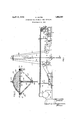
- Fig. 1 is a diagram showing such parts of the drilling rig as are concerned in the practice of my invention
- Fig. 2 is a detail of the apparatus used to control the link motion of the secondary feeding mechanism indicated at 70 in Fig. 1.
- Fig. 1 10 is the outline of a derrick, 11 the crown block, 12 the travelling block, 13 the swivel hook, 14 the drill stem, 15 the rotary table and 16 the bit.
- the drilling engine is indicated at 17 this may be any type of steam engine, though a twin engine is to he preferred.
- This engine drives the rotary table through a bevel gear 18 and also actuates the main winding drum 19 35 through sprockets and chains 20 and 21.
- the drilling engine is indicated at 17 this may be any type of steam engine, though a twin engine is to he preferred.
- This engine drives the rotary table through a bevel gear 18 and also actuates the main winding drum 19 35 through sprockets and chains 20 and 21.
- - drilling line 22 is in part wound on the drum 19, then passed through the blocks 11 and 12 and the outer end wound on the calf wheel hoist drum 23.
- the rig is entirely conventional and only the essential, outlines are indicated.
- the calf wheel drum is actuated by a secondary feeding engine 24 through a suitable combination of pulleys 25-25 and belts 2626 or corresponding sprockets and chains.
- the feeding engine 24 must be a steam engine with link motion and may be an ordinary drilling engine, though a twin engine is to be preferred .as having no dead center-an important consideration in a device which is to be controlled automatically.
- a boiler 27 supplies steam to the drilling engine through a pipe 28 controlled by a hand. throttle 29 and to the feeding engine through a. pipe 30 controlled by a hand throttle 31.
- a pipe 49 which may be of small diameter, afl'ords communication between pipe 28 and a diaphragm regulator which is shown in more-detailin Fig. 2.
- Pipe 49 must branch from pipe 28 at a point between the throttle 29 and the steam chest of the drilling engine, and the latter pipe must be of such diameter that the flow of steam to the engine will not be throttled therein.
- the end of pipe 49 must be in free communication with the interior of the steam chest, in order that the momentary pressure within the steam chest may be instantly transmitted to the regulator 50.
- This pipe will rapidly fill with condensed water in such parts as do not drain back to the steam chest, but for the purpose of Referring now to Figs.
- the diaphragm regulator 50 consists of a domed cover or bowl 59, a flexible liquid-tight diaphragm 60, a ring 61 retaining the diaphragm against the rim of the bowl, straps 62 by means of which the assembly is supported in space relative to the apparatus which it operates, bolts 63, a thrust pin 64 hearing on a pad 65 in the center of the diaphragm, a collar 66 on the pin, a stiff open coil spring 67 hearing on the collar, a yoke 68 and a nut 69 passing through the yoke and adapted to adjust the pressure with which the spring urges the thrust pin toward the diaphragm.
- the diaphragm When the bowl is filled with liquid under pressure through pipe 49 the diaphragm will be deflected outwardly and the pin thrust when the main drilling engine must be provided with a link motion for controlling the throw of the valves, the valve link being indicated at 70 in the figure.
- the straps 62-62 shown in Fig. 1 support the diaphra regulator in some convenient fixed re ation to the en 'ne.
- To one of these stra s is pinned a lever 1 having at one end an a justable weight 72 and being rovided at the opposite end to the drag 1m 73 which is attached to valve link 70 in the usual manner.
- the lower end of the thrust pin 64 is inned tolever 71 as at the point 74.
- the ins referred to should be as nearly friction ess as possible and may desirably be rovided with small ball or roller bearings.
- e wei ht 72 should be adjusted to balance the weig t of the valve link and the drag link.
- the spring 67 should be so adjusted that engine 17 is in normal operation under full oad and the liquid in the regulating system .under its normal operating pressure, the diaphragm will be in its neutral or plane position.
- the thrust pin 64 should be of such length that when the diaphragm is in neutral position the lever 71 will be substantially horizontal.
- the length of drag link 73 should be such that'with the lever in this position the valve link will be so positioned as to admit a small quantity of steam to the engine in a windingin direction. Finally, the lever should be so supported in relation to point 7 4 that an expansion of the diaphragm will so move the valve link as to increase the feed of steam in the said direction.
- the apparatus is operated and functions in the following manner. Assuming the apparatus to be at rest with the tools on the bottom of the hole, a sufiicient length of the dead end of the line around calf wheel winding drum 23 and the remainder of the line on main winding drum 19, (the brakes on this drum being locked) throttle 31 is opened to admit steam to the feedin engine 24 and the free end of lever epressed by hand or by means of a temporary weight to admit a free flow of steam in a winding-in direction, the bit being thus lifted free of the bottom of the hole.
- Valve 29 is now opened to admit an operating supply of steam to drilling engine 17 and the pressure in the steam chest immediately rises. This rise in pressure being transmitted to bowl 59 the diaphragm is distended and link is thus again shifted to reverse feeding engine 24 to a winding-in direction which .tends to again lift the fit free of the bottom.
- the line is thus paid out and the pressure of the bit on the bottom of the hole and its resistance to rotation are increased.
- the steam presure in the steam chest of the drilling engine rises, increasing the ressure in the regulator, the valve link is s ifted into a winding-in position, and the toolsare retrieved.
- the tools may be maintained in. such degree of contact with the bottom as will maintain, without exceeding, that desired maximum torsional stress on the drill string at which the greatest amount of hole is made without overstressin the drill ipe.
- the amount of steam required to hold the engine stationary will vary with the load on drum 23 and the feed may be controlled by small adjustments of the length of the drag link, which for this purpose should be so constructed as to have its length varied without interrupting operation, as by a nut with opposed threads, a hand operated cam, a pair of adjusting screws adapted to move one of the pin hearings or any of the well known means for varying the length of a linkage rod.
- valve link is set on center so as to admit no steam to the feeding engine while the drilling engine is carrying its normal drilling load. In such remain stationary long enough to become cold, as when drilling in very hard formation and, to prevent sluggishness in starting, not only the cylinders but also the steam chest should be continuously bled to avoid accumulation of water.
- a mechanism for drilling wells by the rotary method said mechanism including a string of drill pipe, a rotary table, a main winding drum, a cable adapted to raise and lower said' pipe andhaving one end wound on said drum, and a steam actuated drilling engine adapted to rotate said table;
- ipe feeding means comprising: a secon ary winding drum having wound thereon the end of said cable opposite first said end; a steam actuated feeding engine operatively connected to said secondary drum, said feeding engine having a valve-controlling link; a diaphragm regulator having its fluid chamber osition relative to said feeding engine; lin (age between the diaphragm of said regulator and the link of said engine whereby the position of said link is altered in response to changes in position of said diaconducting channel connecting the, steam chest of said drilling engine with the fluid chamber of said regulator whereby a change in the pressure within said steam chest is caused to alter the position of said diaphragm relative to said regulator
- a mechanism for drilling wells by the rotary method including a string of drill pipe, a rotary table, a main winding drum, lower said pipe and having one' end wound on said drum, and asteam actuated drilling engine adapted to rotate said table; pipe feeding means comprising: a secondary winding drum having wound thereon the end of said cable opposite first said end; a steam actuated feeding engine operatively connected to said secondary drum, said feeding engine having a valve-controlling link, and distensible means actuated by and responsive to variations in steam chest pressure in first said engine adapted to vary the position of said link relative to second said engine.
Landscapes
- Engineering & Computer Science (AREA)
- Life Sciences & Earth Sciences (AREA)
- Geology (AREA)
- Mining & Mineral Resources (AREA)
- Mechanical Engineering (AREA)
- Physics & Mathematics (AREA)
- Environmental & Geological Engineering (AREA)
- Fluid Mechanics (AREA)
- General Life Sciences & Earth Sciences (AREA)
- Geochemistry & Mineralogy (AREA)
- Treatment Of Fiber Materials (AREA)
Description
April 12, 1932. H. HAYES APPARATUS FOR AUTOMATIC WELL DRILLING TUE A Y HAYES Nl/ENTOR Filed March 4. 3.931
Mk HN \N.
I ATTORNEY l was mm or names, caniroam mans-rue AUTOMATIC wmzr. nnmm'c Application ma mm 4, 1m. mm No. 520,072.
The object of my invention is to provide a means for automatically controlling the feed of a string of drill pipe in response to variations in the trosional stress on. the upper end of the string.
Y My invention refers to, the class of drilling apparatus in which a steam engine is used to actuate the rotary table and the hoisting drums, and comprises a steam-actuated secondary feeding engine and a drum operated thereby, together with means through which the variations'in steam pressure in the cylinders of the drilling engine are caused to control the direction and the speed of rotation of m the feeding engine.
The object and advantages of my invention may best be understood with reference to the.
attached drawings, showing an illustrative embodiment thereof, in which: 1
Fig. 1 is a diagram showing such parts of the drilling rig as are concerned in the practice of my invention;
Fig. 2 is a detail of the apparatus used to control the link motion of the secondary feeding mechanism indicated at 70 in Fig. 1.
Referring first to Fig. 1, 10 is the outline of a derrick, 11 the crown block, 12 the travelling block, 13 the swivel hook, 14 the drill stem, 15 the rotary table and 16 the bit. The drilling engine is indicated at 17 this may be any type of steam engine, though a twin engine is to he preferred. This engine drives the rotary table through a bevel gear 18 and also actuates the main winding drum 19 35 through sprockets and chains 20 and 21. The
- drilling line 22 is in part wound on the drum 19, then passed through the blocks 11 and 12 and the outer end wound on the calf wheel hoist drum 23. Up to this point the rig is entirely conventional and only the essential, outlines are indicated.
- The calf wheel drum is actuated by a secondary feeding engine 24 through a suitable combination of pulleys 25-25 and belts 2626 or corresponding sprockets and chains. For the purpose of my invention the feeding engine 24 must be a steam engine with link motion and may be an ordinary drilling engine, though a twin engine is to be preferred .as having no dead center-an important consideration in a device which is to be controlled automatically.
PATENT orr cs A boiler 27 supplies steam to the drilling engine through a pipe 28 controlled by a hand. throttle 29 and to the feeding engine through a. pipe 30 controlled by a hand throttle 31.
A pipe 49, which may be of small diameter, afl'ords communication between pipe 28 and a diaphragm regulator which is shown in more-detailin Fig. 2. Pipe 49 must branch from pipe 28 at a point between the throttle 29 and the steam chest of the drilling engine, and the latter pipe must be of such diameter that the flow of steam to the engine will not be throttled therein. In other words, the end of pipe 49 must be in free communication with the interior of the steam chest, in order that the momentary pressure within the steam chest may be instantly transmitted to the regulator 50. This pipe will rapidly fill with condensed water in such parts as do not drain back to the steam chest, but for the purpose of Referring now to Figs. 1 and 2, the diaphragm regulator 50 consists of a domed cover or bowl 59, a flexible liquid-tight diaphragm 60, a ring 61 retaining the diaphragm against the rim of the bowl, straps 62 by means of which the assembly is supported in space relative to the apparatus which it operates, bolts 63, a thrust pin 64 hearing on a pad 65 in the center of the diaphragm, a collar 66 on the pin, a stiff open coil spring 67 hearing on the collar, a yoke 68 and a nut 69 passing through the yoke and adapted to adjust the pressure with which the spring urges the thrust pin toward the diaphragm.
When the bowl is filled with liquid under pressure through pipe 49 the diaphragm will be deflected outwardly and the pin thrust when the main drilling engine must be provided with a link motion for controlling the throw of the valves, the valve link being indicated at 70 in the figure. The straps 62-62 shown in Fig. 1 support the diaphra regulator in some convenient fixed re ation to the en 'ne. To one of these stra s is pinned a lever 1 having at one end an a justable weight 72 and being rovided at the opposite end to the drag 1m 73 which is attached to valve link 70 in the usual manner. The lower end of the thrust pin 64 is inned tolever 71 as at the point 74.
onnected in this manner an outward movement of diaphragm 60, due to increased pressure in bowl 59, causes a lifting of the valve link 70 while a decrease in ressure permits an inward movement of t e diaphragm and a corresponding depression of the link. By pinning the lever 71 to the right instead of the left strap the direction. of
movement of the dia hragm will be reversed. In practice the relation is determined by the direction in which the engine is set as regards the rig.
In an actual arrangement of this appara-,
tus the ins referred to should be as nearly friction ess as possible and may desirably be rovided with small ball or roller bearings.
e wei ht 72 should be adjusted to balance the weig t of the valve link and the drag link. The spring 67 should be so adjusted that engine 17 is in normal operation under full oad and the liquid in the regulating system .under its normal operating pressure, the diaphragm will be in its neutral or plane position. The thrust pin 64 should be of such length that when the diaphragm is in neutral position the lever 71 will be substantially horizontal.
The length of drag link 73 should be such that'with the lever in this position the valve link will be so positioned as to admit a small quantity of steam to the engine in a windingin direction. Finally, the lever should be so supported in relation to point 7 4 that an expansion of the diaphragm will so move the valve link as to increase the feed of steam in the said direction.
Arranged as described, the apparatus is operated and functions in the following manner. Assuming the apparatus to be at rest with the tools on the bottom of the hole, a sufiicient length of the dead end of the line around calf wheel winding drum 23 and the remainder of the line on main winding drum 19, (the brakes on this drum being locked) throttle 31 is opened to admit steam to the feedin engine 24 and the free end of lever epressed by hand or by means of a temporary weight to admit a free flow of steam in a winding-in direction, the bit being thus lifted free of the bottom of the hole.
A small amount of steam is now admitted to drilling engine -17 and the tools allowed to run free until the regulating system inthe diaphragm7 past its neutral position, thus 0 until engine 24 reverses its directhe bit shifting lin direction and runs in an unwindin tion. The line is thus paid out unti? engages the bottom of the hole.
Valve 29 is now opened to admit an operating supply of steam to drilling engine 17 and the pressure in the steam chest immediately rises. This rise in pressure being transmitted to bowl 59 the diaphragm is distended and link is thus again shifted to reverse feeding engine 24 to a winding-in direction which .tends to again lift the fit free of the bottom.
At this point the operation of the ap aratus becomes automatic up to the point w ere all the line on drum 23 is paid out or until the lengthening of the drill pipe is required. As the bit drills itself free the steam chest pressure in the drilling engine decreases, the regulator pressure falls and the valve link is shifted'into ortowa-rd an unwinding setting of the valves in the feeding engine.
The line is thus paid out and the pressure of the bit on the bottom of the hole and its resistance to rotation are increased. The steam presure in the steam chest of the drilling engine rises, increasing the ressure in the regulator, the valve link is s ifted into a winding-in position, and the toolsare retrieved. By a proper balancing of these two effects the tools may be maintained in. such degree of contact with the bottom as will maintain, without exceeding, that desired maximum torsional stress on the drill string at which the greatest amount of hole is made without overstressin the drill ipe.
It will be seen t at with t e apparatus functioning in this manner the greater part of the weight of the drill string is in effect suspended from the reel 23, which thus tends to unwind and pay out line, and that this tendency must be resisted in some manner. In the description previously given it is assumed that the transmission arrange-.
ments (as the pulleys and belts- 25 and 26) is reversible and that the load on the winding drum is thus transmitted back to the engine and tends to reverse it, this tendency increasing as the length and weight of the drill string increases.
In the above description this tendency is resisted by such setting of the valve link as will admit a small amount of steam to the engine in a winding-in direction at such times as the drilling engine is operating at normal case the engine may ing out of line for feeding will phragm, and a fluid drilling pressure, this quantity of steam being such as will maintain the feeding engine stationary against the load tending to reverse it. This steam wouldcondense. and fill the engine cylinders with water, and in operating in this manner the cylinders should be provided with bleeders which should be left slightly open at all times. The amount of steam required to hold the engine stationary will vary with the load on drum 23 and the feed may be controlled by small adjustments of the length of the drag link, which for this purpose should be so constructed as to have its length varied without interrupting operation, as by a nut with opposed threads, a hand operated cam, a pair of adjusting screws adapted to move one of the pin hearings or any of the well known means for varying the length of a linkage rod.
If the transmission between engine 24 and drum 23 be so constructed as to be irreversible-,asv by the interposition of a worm at some pointthe dead load will be carried by the transmission, there will be no tendency of the load to reverse the engine and the payrequire the a admission of steam to the engine in an unwinding direction. In this case the valve link is set on center so as to admit no steam to the feeding engine while the drilling engine is carrying its normal drilling load. In such remain stationary long enough to become cold, as when drilling in very hard formation and, to prevent sluggishness in starting, not only the cylinders but also the steam chest should be continuously bled to avoid accumulation of water. While I have shown and described the well known diaphragm pressure regulator as a preferred means for actuating the valve link of the feeding engine it will be understood that any alternative distensible means, such as a piston operating in a cylinder, may be used for this purpose.
I claim as my invention: 1. In a mechanism for drilling wells by the rotary method, said mechanism including a string of drill pipe, a rotary table, a main winding drum, a cable adapted to raise and lower said' pipe andhaving one end wound on said drum, and a steam actuated drilling engine adapted to rotate said table; ipe feeding means comprising: a secon ary winding drum having wound thereon the end of said cable opposite first said end; a steam actuated feeding engine operatively connected to said secondary drum, said feeding engine having a valve-controlling link; a diaphragm regulator having its fluid chamber osition relative to said feeding engine; lin (age between the diaphragm of said regulator and the link of said engine whereby the position of said link is altered in response to changes in position of said diaconducting channel connecting the, steam chest of said drilling engine with the fluid chamber of said regulator whereby a change in the pressure within said steam chest is caused to alter the position of said diaphragm relative to said regulator and the position of said link relative to said feeding engine.
2. In a mechanism for drilling wells by the rotary method, said mechanism including a string of drill pipe, a rotary table, a main winding drum, lower said pipe and having one' end wound on said drum, and asteam actuated drilling engine adapted to rotate said table; pipe feeding means comprising: a secondary winding drum having wound thereon the end of said cable opposite first said end; a steam actuated feeding engine operatively connected to said secondary drum, said feeding engine having a valve-controlling link, and distensible means actuated by and responsive to variations in steam chest pressure in first said engine adapted to vary the position of said link relative to second said engine.
' In witness that I claim the foregoing I have hereunto subscribed my name this 26th day of February, 1931.
. HARRY HAYES.
a cable adapted to raise and
Priority Applications (1)
| Application Number | Priority Date | Filing Date | Title |
|---|---|---|---|
| US520072A US1853351A (en) | 1931-03-04 | 1931-03-04 | Apparatus for automatic well drilling |
Applications Claiming Priority (1)
| Application Number | Priority Date | Filing Date | Title |
|---|---|---|---|
| US520072A US1853351A (en) | 1931-03-04 | 1931-03-04 | Apparatus for automatic well drilling |
Publications (1)
| Publication Number | Publication Date |
|---|---|
| US1853351A true US1853351A (en) | 1932-04-12 |
Family
ID=24071087
Family Applications (1)
| Application Number | Title | Priority Date | Filing Date |
|---|---|---|---|
| US520072A Expired - Lifetime US1853351A (en) | 1931-03-04 | 1931-03-04 | Apparatus for automatic well drilling |
Country Status (1)
| Country | Link |
|---|---|
| US (1) | US1853351A (en) |
Cited By (7)
| Publication number | Priority date | Publication date | Assignee | Title |
|---|---|---|---|---|
| US20240287970A1 (en) * | 2023-02-28 | 2024-08-29 | EnhancedGEO Holdings, LLC | Drilling equipment powered by geothermal energy |
| US12291965B2 (en) | 2023-09-08 | 2025-05-06 | EnhancedGEO Holdings, LLC | Detecting entry into and drilling through a magma reservoir |
| US12297711B2 (en) | 2023-04-28 | 2025-05-13 | EnhancedGEO Holdings, LLC | Casing a wellbore in magma |
| US12305486B2 (en) | 2022-05-01 | 2025-05-20 | EnhancedGEO Holdings, LLC | Wellbore for extracting heat from magma bodies |
| US12319573B2 (en) | 2023-03-03 | 2025-06-03 | EnhancedGEO Holdings, LLC | Molten-salt mediated thermochemical reactions using geothermal energy |
| US12326278B2 (en) | 2022-02-28 | 2025-06-10 | EnhancedGEO Holdings, LLC | Geothermal power from superhot geothermal fluid and magma reservoirs |
| US12504204B2 (en) | 2023-02-10 | 2025-12-23 | EnhancedGEO Holdings, LLC | Partially cased wellbore in magma reservoir |
-
1931
- 1931-03-04 US US520072A patent/US1853351A/en not_active Expired - Lifetime
Cited By (9)
| Publication number | Priority date | Publication date | Assignee | Title |
|---|---|---|---|---|
| US12326278B2 (en) | 2022-02-28 | 2025-06-10 | EnhancedGEO Holdings, LLC | Geothermal power from superhot geothermal fluid and magma reservoirs |
| US12305486B2 (en) | 2022-05-01 | 2025-05-20 | EnhancedGEO Holdings, LLC | Wellbore for extracting heat from magma bodies |
| US12504204B2 (en) | 2023-02-10 | 2025-12-23 | EnhancedGEO Holdings, LLC | Partially cased wellbore in magma reservoir |
| US12504203B2 (en) | 2023-02-10 | 2025-12-23 | EnhancedGEO Holdings, LLC | Reverse-flow magma-based geothermal generation |
| US12516849B2 (en) | 2023-02-10 | 2026-01-06 | EnhancedGEO Holdings, LLC | Molten salt as heat transfer fluid in magma geothermal system |
| US20240287970A1 (en) * | 2023-02-28 | 2024-08-29 | EnhancedGEO Holdings, LLC | Drilling equipment powered by geothermal energy |
| US12319573B2 (en) | 2023-03-03 | 2025-06-03 | EnhancedGEO Holdings, LLC | Molten-salt mediated thermochemical reactions using geothermal energy |
| US12297711B2 (en) | 2023-04-28 | 2025-05-13 | EnhancedGEO Holdings, LLC | Casing a wellbore in magma |
| US12291965B2 (en) | 2023-09-08 | 2025-05-06 | EnhancedGEO Holdings, LLC | Detecting entry into and drilling through a magma reservoir |
Similar Documents
| Publication | Publication Date | Title |
|---|---|---|
| US2554381A (en) | Ship roll energy device | |
| US1853351A (en) | Apparatus for automatic well drilling | |
| US3260508A (en) | Balancing hoist | |
| US3901478A (en) | Crane incorporating vertical motion apparatus | |
| US2950086A (en) | Drilling control | |
| US2260922A (en) | Fluid controlled guide for elevator cars | |
| US2265314A (en) | Power transmission | |
| US2657011A (en) | Means for controlling hoists and winches | |
| US3031169A (en) | Apparatus for automatically controlling drilling | |
| US2131868A (en) | Well measuring | |
| US2109297A (en) | Hydraulic control for drilling rigs | |
| US1919611A (en) | Apparatus for automatically regulating the drill pressure in deepboring plants | |
| US2639103A (en) | Vehicle reel control | |
| US2244830A (en) | Power transmission | |
| US2759702A (en) | Drilling control | |
| US1779581A (en) | Weight regulator and indicator | |
| US1902972A (en) | Mooring and hoisting apparatus | |
| US2709071A (en) | Hydro-gear retrieving feed apparatus for rotary drilling | |
| US1711886A (en) | Brake equalizer | |
| US2634099A (en) | Automatic drilling machine | |
| US2169629A (en) | Braking apparatus | |
| US2670925A (en) | Automatic control for keeping predetermined weight on a drilling bit | |
| US2672222A (en) | Fluid pressure control apparatus for rotary well drilling equipment | |
| US2642962A (en) | Fluid pressure brake control apparatus | |
| US1924317A (en) | Mechanism for controlling pressure and feed of tools of rotary well drilling rigs |