US1853349A - Form for felting fibrous receptacles - Google Patents
Form for felting fibrous receptacles Download PDFInfo
- Publication number
- US1853349A US1853349A US516153A US51615331A US1853349A US 1853349 A US1853349 A US 1853349A US 516153 A US516153 A US 516153A US 51615331 A US51615331 A US 51615331A US 1853349 A US1853349 A US 1853349A
- Authority
- US
- United States
- Prior art keywords
- fibrous
- lobes
- receptacles
- felting
- receptacle
- Prior art date
- Legal status (The legal status is an assumption and is not a legal conclusion. Google has not performed a legal analysis and makes no representation as to the accuracy of the status listed.)
- Expired - Lifetime
Links
Images
Classifications
-
- D—TEXTILES; PAPER
- D21—PAPER-MAKING; PRODUCTION OF CELLULOSE
- D21J—FIBREBOARD; MANUFACTURE OF ARTICLES FROM CELLULOSIC FIBROUS SUSPENSIONS OR FROM PAPIER-MACHE
- D21J7/00—Manufacture of hollow articles from fibre suspensions or papier-mâché by deposition of fibres in or on a wire-net mould
Definitions
- This invention relates to improvements in forms for the felting of fibrous receptacles, and refers particularly to the provision of a form comprising a plurality of foraminated separable portions.
- a fibrous receptacle is adapted to be felted upon the outer surface of said form, and subsequent to the felting operation the portions comprising the form may be removed from the interior of the felted receptacle.
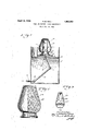
- Fig. 1 is a sectional elevation of a felting vat into which the form comprising my invention may be immersed.
- Fig. 2 is' an elevational view, partly'in section, illustrating the fibrous receptacle constructed by the use of my invention.
- Fig. 3 is a lobe or section of the main body portion of the form.
- 1 indicates an open top vat or tank which may be adapted to contain a quantity of fibrous pulp 2.
- a pipe 3 may pass through the lower wall of the vat 1 and may be connected within said vat by means of a swing or swivel coupling 4 to pipe 5.
- Pipe 5 may in turn be connected to pipe 6 by means of swing coupling 17.
- the opposite end of pipe 6 may be connected to swing coupling 8, which in turn connects pipe 6 with nipple 9 which may pass through platform 10 and support saidv platform.
- a form 11 utilized in the felting of a fibrous receptacle such as that shown at 12 in Fig. 2 may be positioned upon latform 10 and may comprise an annular nec forming portion 13 provided with a plurality of transverse apertures 14.
- the neck forming portion '13 may terminate at its upper end in a cylindrical member 15 which maybe open at its, upper end, said cylindrical member being provided with a plurality of apertures 16.
- the body portion 17 of the form 11 may comprise a plurality of lobes or segments '18provided. with apertures 19.
- the upper inner surface of each of the lobes 18 may have a projecting segmental member 19 formed thereon which,
- the body portion 17 comprising the lobes 18 is adapted to bemounted upon the annular neck forming portion 13 and the cylinder 15, and the boss 20 is adapted to be disposed within the upper portion of said cylinder. In this manner the cylinder provides a support for the lobes 18,and by the provision of the boss 20 said lobes are maintained in desired position.
- the lower edges 21 of the lobes 18 may be adapted to be mounted upon offset shoulder 22 formed upon the upper portion of the neck forming member 13.
- a suitable quantity of fibrous pulp 2 may be maintained within the vat 1.
- the consistency or concentration of the pulp'solution will be dependent upon the type of receptacle desired to be constructed.
- the level of the pulp maintained in the Vat 1 may be such that when the formand the supporting platform are in the approx mate position shown in Fig. 1 the platform 1s adjacent the surface of the pulp.
- the op posite end of the pipe 3 (not shown) may e connected to a vacuum pump or the like which may be adapted to create a suction action within the pipes 9, 6, 5 and 3.
- the form 11 may be disposed upon platform 10 in inverted position, that IS, w th the neck forming portion 13 in contact wlth 10. In this manner air or other fluid contained within the body portion of the form 11 may be withdrawn through the above mentioned pipes.
- the arrangement is suchthat simultaneously with the establishing of a condition of. vacuum within the form 11 the platform 10 will be lowered into the bodyof the pulp 2.
- the water comprising the carrier for the fibrous, material constituting the pulp will be drawn "through lobes 18 and the annular neck forming mem-.
- screen 23 may bedisp s p provision of this screen the finished product, as shown at 12, will have a relatively smooth interior surface.
- the screen facilitates the subsequent removal of the forlm from the interior of the felted receptac e.
- the platform 10 may be raise a The form 11 with the deposited fibers there on may then be removed from the platform 10, and inasmuch as the neck formin member 13 and the .cylinder 15 taper slig tly toward the interior of the receptacle elements 13 and 15 may readily be removed from the interior of said receptacle. Bythe removal of said elements the lobes 18 remain unsup orted within the receptacle. Lugs 24 may be embedded in the inner surface of each of the lobes 18' and may serve as rips or hand-' holds for the removal of the lobe the mouthof the receptacle.
- the body portion 17 of the form may be divided into a sufiicient number of lobes so as to provide the lobesof 'sufiicient dimensions to be removed through the mouth of the receptacle.
- receptacle may then be dried.
- a form for felting fibrous receptacles which comprises, a perforated neck formi member, an extension 78 carried by said mem r, and a plurality of erforated body forming lobes cooperatively disposed with respect to the neck forming member and extension.
- .fibrous receptacles which comprises, an annular perforated neck forming member, a cylindrical extension carried b said member and a plurality of perforated body forming lobes co-operatively di (1 with respect to the neck formingmem r and cylindrical extenslon.
- a form for felting 2- In combination, a form for felting fibrous receptacles which comprises, a hammated neck forming member, having a central opening, a cylindrical extension carried by said member provided with a plurality goipefrtures anld his plurality of floraminated orming o co-o rative y dlsposed' mt to the nec forming member and cylindrical extension the ma or trans verse en sion of said lobes being less than I the ma or distance between defining edgesof said central opening member.
- fibrous receptacles whi comp a foraminatedneck forming membenadapted I to be disposed upon a platform in inverted ll position, a cylindrical extension carried by in the neck forming a form for I
Landscapes
- Engineering & Computer Science (AREA)
- Manufacturing & Machinery (AREA)
- Paper (AREA)
Description
E. HALL FORM FOR FELTI'NG FIBROUS RECEP TACLES A ril 12, 1932.
Filed Feb. 16,, 1931 L 'clzarafffaZZ,
Patented Apr. 12,; 1932 UNITED? STATE-Si V v i BICHABID E. HALL, OF OLEAN, NEW YORK, ASSIGNOR, BY;MESNE ASSIGNMENTS,
ABVEY-WARE CORPORATION, A CORPORATION OF DELAWARE NBMFOBIEL TING FIBROUS REGEETAOLES I Application nledrebruary 16, 1981. Serial No. 516,153. I v
This invention relates to improvements in forms for the felting of fibrous receptacles, and refers particularly to the provision of a form comprising a plurality of foraminated separable portions. A fibrous receptacle is adapted to be felted upon the outer surface of said form, and subsequent to the felting operation the portions comprising the form may be removed from the interior of the felted receptacle.
Utility, objects and advantages of the pres- #fil'lt invention will be apparent from the accompanying drawings and following detail description.
:In the drawings, Fig. 1 is a sectional elevation of a felting vat into which the form comprising my invention may be immersed.
Fig. 2 is' an elevational view, partly'in section, illustrating the fibrous receptacle constructed by the use of my invention.
Fig. 3 is a lobe or section of the main body portion of the form.
Beferring in detail to the drawings, 1 indicates an open top vat or tank which may be adapted to contain a quantity of fibrous pulp 2. A pipe 3 may pass through the lower wall of the vat 1 and may be connected within said vat by means of a swing or swivel coupling 4 to pipe 5. Pipe 5 may in turn be connected to pipe 6 by means of swing coupling 17. The opposite end of pipe 6 may be connected to swing coupling 8, which in turn connects pipe 6 with nipple 9 which may pass through platform 10 and support saidv platform. T
A form 11 utilized in the felting of a fibrous receptacle such as that shown at 12 in Fig. 2 may be positioned upon latform 10 and may comprise an annular nec forming portion 13 provided with a plurality of transverse apertures 14. The neck forming portion '13 may terminate at its upper end in a cylindrical member 15 which maybe open at its, upper end, said cylindrical member being provided with a plurality of apertures 16. The body portion 17 of the form 11 may comprise a plurality of lobes or segments '18provided. with apertures 19. The upper inner surface of each of the lobes 18 may have a projecting segmental member 19 formed thereon which,
'the platform It can readily be seenthat PATENT OFFICE/ when the segments 18 have been disposedin I operative position, form a downwardly projecting boss20. r
The body portion 17 comprising the lobes 18 is adapted to bemounted upon the annular neck forming portion 13 and the cylinder 15, and the boss 20 is adapted to be disposed within the upper portion of said cylinder. In this manner the cylinder provides a support for the lobes 18,and by the provision of the boss 20 said lobes are maintained in desired position. The lower edges 21 of the lobes 18 may be adapted to be mounted upon offset shoulder 22 formed upon the upper portion of the neck forming member 13.
p In utilizing my invention a suitable quantity of fibrous pulp 2 may be maintained within the vat 1. The consistency or concentration of the pulp'solution will be dependent upon the type of receptacle desired to be constructed. The level of the pulp maintained in the Vat 1 may be such that when the formand the supporting platform are in the approx mate position shown in Fig. 1 the platform 1s adjacent the surface of the pulp. The op posite end of the pipe 3 (not shown) may e connected to a vacuum pump or the like which may be adapted to create a suction action within the pipes 9, 6, 5 and 3. v
The form 11 may be disposed upon platform 10 in inverted position, that IS, w th the neck forming portion 13 in contact wlth 10. In this manner air or other fluid contained within the body portion of the form 11 may be withdrawn through the above mentioned pipes. The arrangement is suchthat simultaneously with the establishing of a condition of. vacuum within the form 11 the platform 10 will be lowered into the bodyof the pulp 2.
the water comprising the carrier for the fibrous, material constituting the pulp will be drawn "through lobes 18 and the annular neck forming mem-.
ber 13. Asithe water is drawn through-said? apertures the fibers carried by saidwater'w will be deposited upon the outer .surfaceiof". the form. A
the outersurface of-thelobes 18. By the.
' After the platform and the form 11 carried thereon has been immersed in the pulp solution 2 a suflicientl long time to 'dBPOSlt 1 a desired thickness of fiber upon the'outer surfatfe' of said form, the platform 10 may be raise a The form 11 with the deposited fibers there on may then be removed from the platform 10, and inasmuch as the neck formin member 13 and the .cylinder 15 taper slig tly toward the interior of the receptacle elements 13 and 15 may readily be removed from the interior of said receptacle. Bythe removal of said elements the lobes 18 remain unsup orted within the receptacle. Lugs 24 may be embedded in the inner surface of each of the lobes 18' and may serve as rips or hand-' holds for the removal of the lobe the mouthof the receptacle.
The body portion 17 of the form may be divided into a sufiicient number of lobes so as to provide the lobesof 'sufiicient dimensions to be removed through the mouth of the receptacle. The
receptacle may then be dried.
. It is to be understood, of course, that my s 18 through said member, said extension being provided with a pluralityof apertures, a plurali of forammated lobes upon said 11 formin member and said cylindrical extention an enclosing said'extension and means for establishing a condition of vacuum within said form.
4.- In combination, a form for felting fibrous receptacles which comprises, a perforated neck formi member, an extension 78 carried by said mem r, and a plurality of erforated body forming lobes cooperatively disposed with respect to the neck forming member and extension.
In'testimony whereof I aflix my si ature. a0 RICHARD E. ALL.
- invention is not to be limited to the particular shape shown in'the drawings inasmuch as it is adaptable to the formation of substantiall any shape vase, and is particularly adagtabe to-the formation of vases, the area of t e mouths of which are less than the area of theintermediate portions thereof. I claim as my invention;
. 1. In .fibrous receptacles which comprises, an annular perforated neck forming member, a cylindrical extension carried b said member and a plurality of perforated body forming lobes co-operatively di (1 with respect to the neck formingmem r and cylindrical extenslon.
combination, a form for felting 2- In combination, a form for felting fibrous receptacles which comprises, a hammated neck forming member, having a central opening, a cylindrical extension carried by said member provided with a plurality goipefrtures anld his plurality of floraminated orming o co-o rative y dlsposed' mt to the nec forming member and cylindrical extension the ma or trans verse en sion of said lobes being less than I the ma or distance between defining edgesof said central opening member.
8. In combination, fibrous receptacles whi comp a foraminatedneck forming membenadapted I to be disposed upon a platform in inverted ll position, a cylindrical extension carried by in the neck forming a form for I
Priority Applications (1)
| Application Number | Priority Date | Filing Date | Title |
|---|---|---|---|
| US516153A US1853349A (en) | 1931-02-16 | 1931-02-16 | Form for felting fibrous receptacles |
Applications Claiming Priority (1)
| Application Number | Priority Date | Filing Date | Title |
|---|---|---|---|
| US516153A US1853349A (en) | 1931-02-16 | 1931-02-16 | Form for felting fibrous receptacles |
Publications (1)
| Publication Number | Publication Date |
|---|---|
| US1853349A true US1853349A (en) | 1932-04-12 |
Family
ID=24054349
Family Applications (1)
| Application Number | Title | Priority Date | Filing Date |
|---|---|---|---|
| US516153A Expired - Lifetime US1853349A (en) | 1931-02-16 | 1931-02-16 | Form for felting fibrous receptacles |
Country Status (1)
| Country | Link |
|---|---|
| US (1) | US1853349A (en) |
Cited By (1)
| Publication number | Priority date | Publication date | Assignee | Title |
|---|---|---|---|---|
| US2424189A (en) * | 1942-11-11 | 1947-07-15 | Canal Nat Bank Of Portland | Pulp molding die |
-
1931
- 1931-02-16 US US516153A patent/US1853349A/en not_active Expired - Lifetime
Cited By (1)
| Publication number | Priority date | Publication date | Assignee | Title |
|---|---|---|---|---|
| US2424189A (en) * | 1942-11-11 | 1947-07-15 | Canal Nat Bank Of Portland | Pulp molding die |
Similar Documents
| Publication | Publication Date | Title |
|---|---|---|
| US2054934A (en) | Paper receptacle | |
| US2488700A (en) | Apparatus for paper manufacture | |
| US1661727A (en) | Method and apparatus for making packing for fragile articles | |
| US1853349A (en) | Form for felting fibrous receptacles | |
| CN207330537U (en) | A kind of more medium filter | |
| US1918782A (en) | Method of and apparatus for forming molded pulp articles | |
| US3016090A (en) | Pulp molding machine | |
| US2337574A (en) | Filter and method for making the same | |
| US2107227A (en) | Dry cleaning machine | |
| US2322586A (en) | Filter | |
| US1848478A (en) | Filter | |
| US2149879A (en) | Pulp molding | |
| US1690528A (en) | Apparatus and method for making fibrous boxes | |
| US1899197A (en) | Art of casting fiber articles | |
| US2116763A (en) | Paper making machine | |
| US3306815A (en) | Apparatus for accretion of fibrous articles on a mold from a slurry of fibers | |
| US1838761A (en) | Integral felted fibrous structure | |
| US2075300A (en) | Filter | |
| US1596976A (en) | Method and apparatus for forming articles by deposition | |
| CN210458638U (en) | Shaping padder auxiliary agent concentration control device | |
| US1536566A (en) | Method of making articles from pulp | |
| CN2316901Y (en) | Domestic rice-washing device | |
| US1882045A (en) | Filtering apparatus | |
| CN108252040A (en) | A kind of washing machine shell and rotary drum washing machine | |
| US1962656A (en) | Method of felting fibrous receptacles having a neck |