US1853347A - Operating device for railway car couplers - Google Patents
Operating device for railway car couplers Download PDFInfo
- Publication number
- US1853347A US1853347A US520199A US52019931A US1853347A US 1853347 A US1853347 A US 1853347A US 520199 A US520199 A US 520199A US 52019931 A US52019931 A US 52019931A US 1853347 A US1853347 A US 1853347A
- Authority
- US
- United States
- Prior art keywords
- car
- lever
- coupler
- operating
- fulcrum
- Prior art date
- Legal status (The legal status is an assumption and is not a legal conclusion. Google has not performed a legal analysis and makes no representation as to the accuracy of the status listed.)
- Expired - Lifetime
Links
Images
Classifications
-
- B—PERFORMING OPERATIONS; TRANSPORTING
- B61—RAILWAYS
- B61G—COUPLINGS; DRAUGHT AND BUFFING APPLIANCES
- B61G3/00—Couplings comprising mating parts of similar shape or form which can be coupled without the use of any additional element or elements
- B61G3/04—Couplings comprising mating parts of similar shape or form which can be coupled without the use of any additional element or elements with coupling head having a guard arm on one side and a knuckle with angularly-disposed nose and tail portions pivoted to the other side thereof, the nose of the knuckle being the coupling part, and means to lock the knuckle in coupling position, e.g. "A.A.R." or "Janney" type
- B61G3/06—Knuckle-locking devices
- B61G3/08—Control devices, e.g. for uncoupling
Definitions
- the invention relates todevices'for manually operating an automatic coupler of a railway car from adjacent the side wall of,
- Coupler consists of unlocking it, throwing the knuckle to open position, or putting the coupler in what is called lock-set position wherein the I knuckle remains unlocked even though the knuckle is in closed position.
- the operating device must allow the coupler to move later- .ally and longitudinally of the car in service withouteftecting the relation of its compo- .nent parts.
- An object of the invention is to provide such an operating device for a car coupler comprising an outer rod mounted upon the car to revolve around its own axis and a lever I mounted upon the car tomove in only a substantially vertical plane and to associate such rod and lever so that a swinging movement of a handle adjacent the outer end of the rod causes the inner end of the rod to bear upon the fulcrum of the lever and by means of eccentric parts of the rod to move the inner end of the lever upwardly and thereby operate the car coupler to which it is connected.
- Another object is to provide asimple means of transforming an operating lever for a car coupler which moves only in a substantially vertical plane to one which includes a revoluble operating rod operable bya depending handle adjacent the side of the car which in my construction is accomplishedby retaining the inner part of the operating lever and reforming the outer part thereof and providing an operating rod revolubly mounted upon the car having its inner end engageable with the fulcrum of the operating lever and a part of the old lever whereby a partial revolution of the operating rod raisesthe inner end of the old lever, which inner end is operably connected to the car coupler.
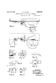
- Fig. 1 shows a partial plan view of a railway car equipped with a standard automatic coupler and a form of my invention
- Fig. 2 is an elevation of Fig. 1.
- Figs. 3 and 4 show the fulcrum which is mounted upon the carfor the operating lever.
- Figs. 5, 6 and 7 show a connecting means between the primary and secondary levers.
- Figs. 8 and 9 show the outer end of the primary operating lever.
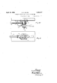
- Figs. 10 and 11 show a modified construction of the operating device.
- Figs. land 2 show a typical applicationof my invention to avrailway car wherein the coupler is supported by. the strikin casting 2 and protrudes from under the en wall of the car-
- The-coupler comprises a head 4, knuckle 5 and lock lifter i6 as well as parts.
- the operating device as shown in Figs. 1-9 inclusive, comprises a fulcrum 1O mounted upon the car and a primary lever '11 having its outer end pivoted to the fulcrum 10 so as to move in substantially a vertical plane and with its inner end 12 adapted for attachment to the carcoupler lock lifter-6,-
- attachment in the form illustrated, comprises a substantially horizontal shank 14 other slidably ext-ending throughan aperture in the lock lifter 6 of the coupler so as to permit lateral movement of the coupler in service.
- the lever swings around the fulcrum 10 in a horizontal plane owing to the particular configuratlon of the outer end 15 of the operating lever,as shown in Figs. 1, 8 a and 9.
- a secondary lever 18 is pivoted at one end to thefulcrum 10 to move only in a substantially vertical plane with its outer end provided with a bearing element "19.. In Figs. 1 and 2 this secondary lever 18 projects toward the center of the car.
- Some means is provided to connect the primary and block 21 is held upon the journal of the fulcrum by the bolt 29 and washer 28, which bolt 29 and washer 28 also retains the levers 11 and 18 upon the block.
- a bracket 50 is mounted upon the car and an operating rod 51 is revolubly supported therein at its outer end adjacent the depending handle 54.
- the inner end of this operating rod 51 is provided with portions 52 53 ofi'set relativeto each other, one'of said portions being positioned adjacent to the fulcrum and the other of said, portions positioned adjacent the bearing 19 of'the secondary lever.
- I In order to retain the component parts of the device in operativerelation during the several andnvarious movements of the coupler in service Ipreferably provide an aperture 70 in the end ofthe secondary lever 18 or 20, as shown in Figs. 1 and 10, through which the operating rod projects while this same objectma be accomplished by providing an aperture (2 inthe fulcrum 10, as shown in Figs. 2 and 3, through which the operating rod projects ordt may be desirable to provide apertures in both of said elements, in which case one of themv should be elongated (as shown in Fig. 3) to accommodate the movements of the operating rod in motion.
- An operating device for a railway car coupler comprising a fulcrum mounted upon a car, a primary lever having its outer end pivoted to said fulcrum to move in a substantially vertical plane and also inasubstantial- 1y horizontal plane with its inner end" adapted for attachment to a car coupler, a secondary lever having one end pivoted to said fulcrum to move onlyin a'substantially vertical plane and having its other end provided with a bearing, means connecting the primary and secondary levers to cause them to move in unison in a vertical plane but permit independent movement thereof in a horizontal plane, av bracket mounted'upon the car, and
- an operating rod revolubly supportedby saidbracket havingit's outer end provided'witha handle and'having its inner end provided with portions offset relative toeach other, one of said portions engaging said fulcrum and the other'of said portions engaging said bearing on the secondarylever whereby arotary movement of the operating rod causes Sflld portions to engage said fulcrum and said bearingrespectively and move the inner end of the primary lever upwardly.
Description
April 12, 1932. e. G. ElLPlN 1,853,347
OPERATING DEVICE-FQR RAILWAY'CAR COUPLERS Filed March 5, 1951 ZSheets-Sheet l 6 awzz z gm 9- 7 fltiorlzls Api'il 12, 1932, G. G. GlLF'lN 1,853,347
OPERATING DEVICE FOR RAILWAY CAR COUPLERS Filed March 5, 1951 2 Sheets-Sheet 2 J1; enior Gard/v 6f G'i/pin/ flitorney Patented Apr. 12, 1932 umreo STATES;
GARTH G. GILPIN, or RIVERSIDE, ILLINOIS, AssIGNoB T umoNiMnTnL rnonuors PATENT QFFICEH COMPANY, on cmoAe LLINoIs, A conronarron' or DELAWARE OPERATING DEVICE FOR RAILWAY CAR GOUIPLERS Application-filed March 5, 1931. Serial No. 520,199.
The invention relates todevices'for manually operating an automatic coupler of a railway car from adjacent the side wall of,
the car so as to eliminate the necessity of the "trainmen from going between the cars to operate the coupler, Operating a coupler consists of unlocking it, throwing the knuckle to open position, or putting the coupler in what is called lock-set position wherein the I knuckle remains unlocked even though the knuckle is in closed position. The operating device must allow the coupler to move later- .ally and longitudinally of the car in service withouteftecting the relation of its compo- .nent parts.
An object of the invention is to provide such an operating device for a car coupler comprising an outer rod mounted upon the car to revolve around its own axis and a lever I mounted upon the car tomove in only a substantially vertical plane and to associate such rod and lever so that a swinging movement of a handle adjacent the outer end of the rod causes the inner end of the rod to bear upon the fulcrum of the lever and by means of eccentric parts of the rod to move the inner end of the lever upwardly and thereby operate the car coupler to which it is connected.
Another object is to provide asimple means of transforming an operating lever for a car coupler which moves only in a substantially vertical plane to one which includes a revoluble operating rod operable bya depending handle adjacent the side of the car which in my construction is accomplishedby retaining the inner part of the operating lever and reforming the outer part thereof and providing an operating rod revolubly mounted upon the car having its inner end engageable with the fulcrum of the operating lever and a part of the old lever whereby a partial revolution of the operating rod raisesthe inner end of the old lever, which inner end is operably connected to the car coupler.
In the drawings;
Fig. 1 shows a partial plan view of a railway car equipped with a standard automatic coupler and a form of my invention- Fig. 2 is an elevation of Fig. 1.
.; Figs. 3 and 4 show the fulcrum which is mounted upon the carfor the operating lever.
Figs. 5, 6 and 7 show a connecting means between the primary and secondary levers.
Figs. 8 and 9 show the outer end of the primary operating lever.
Figs. 10 and 11 show a modified construction of the operating device.
Figs. land 2 show a typical applicationof my invention to avrailway car wherein the coupler is supported by. the strikin casting 2 and protrudes from under the en wall of the car- The-coupler comprises a head 4, knuckle 5 and lock lifter i6 as well as parts.
The operating device, as shown in Figs. 1-9 inclusive, comprises a fulcrum 1O mounted upon the car and a primary lever '11 having its outer end pivoted to the fulcrum 10 so as to move in substantially a vertical plane and with its inner end 12 adapted for attachment to the carcoupler lock lifter-6,-
which attachment, in the form illustrated, comprises a substantially horizontal shank 14 other slidably ext-ending throughan aperture in the lock lifter 6 of the coupler so as to permit lateral movement of the coupler in service. When the. coupler moves longitudinally of the car, the lever swings around the fulcrum 10 in a horizontal plane owing to the particular configuratlon of the outer end 15 of the operating lever,as shown in Figs. 1, 8 a and 9. A secondary lever 18 is pivoted at one end to thefulcrum 10 to move only in a substantially vertical plane with its outer end provided with a bearing element "19.. In Figs. 1 and 2 this secondary lever 18 projects toward the center of the car. Some means is provided to connect the primary and block 21 is held upon the journal of the fulcrum by the bolt 29 and washer 28, which bolt 29 and washer 28 also retains the levers 11 and 18 upon the block.
A bracket 50 is mounted upon the car and an operating rod 51 is revolubly supported therein at its outer end adjacent the depending handle 54. The inner end of this operating rod 51 is provided with portions 52 53 ofi'set relativeto each other, one'of said portions being positioned adjacent to the fulcrum and the other of said, portions positioned adjacent the bearing 19 of'the secondary lever.
By this arrangement the lever is-permitted to move with the horizontal movements of the coupler in service without disturbing the op erating rod or. altering the relation of the handle 54 to the sideof the car.- The relation of this handle Set to the side of the car 2a} is specified by the safety appliance act of the Interstate Commerce Commission.
When the device is operated a swinging movementof the handle 54 of the operating rod 51 causes the portions 52.53 on' its inner end'to engage the fulcrumlO and bearing 19 respectively. which moves'the innerend ofthe primary lever'll ina vertical plane andalso movesthe primary lever 11. through a vertical plane and operates the coupler.
In order to retain the component parts of the device in operativerelation during the several andnvarious movements of the coupler in service Ipreferably provide an aperture 70 in the end ofthe secondary lever 18 or 20, as shown in Figs. 1 and 10, through which the operating rod projects while this same objectma be accomplished by providing an aperture (2 inthe fulcrum 10, as shown in Figs. 2 and 3, through which the operating rod projects ordt may be desirable to provide apertures in both of said elements, in which case one of themv should be elongated (as shown in Fig. 3) to accommodate the movements of the operating rod in motion.
* I The lugs 80 shown in. Figs. 5, 6 and 7 entionwherein the secondary lever 20 projectstowards the side of the carand the end of the operating rod extends from the fulcrum' 61 and an intermediate portion ofthe oper: ating rod 60 engages the outer end 62 'of'the secondary lever 20.
The. accompanying drawings illustrate the preferred form ofthe invention, though itis to be understood'that the invention is not limited to the. exact details of construction shown anddescribed, as it is obvious'that various, modifications thereof, within the I claim:
An operating device for a railway car coupler comprising a fulcrum mounted upon a car, a primary lever having its outer end pivoted to said fulcrum to move in a substantially vertical plane and also inasubstantial- 1y horizontal plane with its inner end" adapted for attachment to a car coupler, a secondary lever having one end pivoted to said fulcrum to move onlyin a'substantially vertical plane and having its other end provided with a bearing, means connecting the primary and secondary levers to cause them to move in unison in a vertical plane but permit independent movement thereof in a horizontal plane, av bracket mounted'upon the car, and
an operating rod revolubly supportedby saidbracket havingit's outer end provided'witha handle and'having its inner end provided with portions offset relative toeach other, one of said portions engaging said fulcrum and the other'of said portions engaging said bearing on the secondarylever whereby arotary movement of the operating rod causes Sflld portions to engage said fulcrum and said bearingrespectively and move the inner end of the primary lever upwardly.
GARTH G. GILPIN.
scopeof the claim, will occurto persons *skilled in the art.
Priority Applications (1)
| Application Number | Priority Date | Filing Date | Title |
|---|---|---|---|
| US520199A US1853347A (en) | 1931-03-05 | 1931-03-05 | Operating device for railway car couplers |
Applications Claiming Priority (1)
| Application Number | Priority Date | Filing Date | Title |
|---|---|---|---|
| US520199A US1853347A (en) | 1931-03-05 | 1931-03-05 | Operating device for railway car couplers |
Publications (1)
| Publication Number | Publication Date |
|---|---|
| US1853347A true US1853347A (en) | 1932-04-12 |
Family
ID=24071578
Family Applications (1)
| Application Number | Title | Priority Date | Filing Date |
|---|---|---|---|
| US520199A Expired - Lifetime US1853347A (en) | 1931-03-05 | 1931-03-05 | Operating device for railway car couplers |
Country Status (1)
| Country | Link |
|---|---|
| US (1) | US1853347A (en) |
-
1931
- 1931-03-05 US US520199A patent/US1853347A/en not_active Expired - Lifetime
Similar Documents
| Publication | Publication Date | Title |
|---|---|---|
| US3206039A (en) | Car coupler | |
| US1853347A (en) | Operating device for railway car couplers | |
| US2498958A (en) | Coupler | |
| US1926117A (en) | Device for operating car couplers | |
| US1897279A (en) | Coupler | |
| US2399263A (en) | Car coupler mechanism | |
| US2184818A (en) | Operating rod for car couplers | |
| US1148049A (en) | Car-coupling. | |
| US1772663A (en) | Coupler-operating device | |
| US1519184A (en) | Automatic train-pipe connecter | |
| US1840165A (en) | Uncoupling mechanism | |
| US1580623A (en) | Car coupler | |
| US982532A (en) | Automatic uncoupling device for car-couplings. | |
| US1475634A (en) | Car coupler | |
| US2051361A (en) | Uncoupling mechanism for railway cars | |
| US2249184A (en) | Coupler operating device | |
| US1595297A (en) | Uncoupling device for car couplers | |
| US2396855A (en) | Coupler mechanism | |
| US1079488A (en) | Car-coupling. | |
| US1439731A (en) | Coupling-controlling mechanism | |
| US538338A (en) | Car-coupling | |
| US2757805A (en) | Railway coupler operating rod | |
| US1800398A (en) | Device for operating car couplers | |
| USRE18631E (en) | kinne | |
| US3146895A (en) | Railway couplers |