US1853342A - Twin tread rail - Google Patents
Twin tread rail Download PDFInfo
- Publication number
- US1853342A US1853342A US514947A US51494731A US1853342A US 1853342 A US1853342 A US 1853342A US 514947 A US514947 A US 514947A US 51494731 A US51494731 A US 51494731A US 1853342 A US1853342 A US 1853342A
- Authority
- US
- United States
- Prior art keywords
- rail
- tread
- twin
- wheel
- inwardly
- Prior art date
- Legal status (The legal status is an assumption and is not a legal conclusion. Google has not performed a legal analysis and makes no representation as to the accuracy of the status listed.)
- Expired - Lifetime
Links
- 239000002184 metal Substances 0.000 description 4
- 229910000831 Steel Inorganic materials 0.000 description 1
- 238000012550 audit Methods 0.000 description 1
- 230000003190 augmentative effect Effects 0.000 description 1
- 238000010276 construction Methods 0.000 description 1
- 230000007547 defect Effects 0.000 description 1
- 230000000694 effects Effects 0.000 description 1
- 230000002349 favourable effect Effects 0.000 description 1
- 230000000750 progressive effect Effects 0.000 description 1
- 239000010959 steel Substances 0.000 description 1
Images
Classifications
-
- E—FIXED CONSTRUCTIONS
- E01—CONSTRUCTION OF ROADS, RAILWAYS, OR BRIDGES
- E01B—PERMANENT WAY; PERMANENT-WAY TOOLS; MACHINES FOR MAKING RAILWAYS OF ALL KINDS
- E01B5/00—Rails; Guard rails; Distance-keeping means for them
- E01B5/02—Rails
- E01B5/06—Reversible or invertible rails
Definitions
- Traction rails in service show peculiar deformative tendencies, some known and some notso well known.
- the wheel-receiving portions in general exhibit a condition of molecular flowage, the surface portions of the metal undergoing progressive movement from the peening action of the wheels, there being in effect a sort of rolling-mill action upon the portions of metal concerned.
- Such portions are elongated, both in the longitudinal and transverse directions, and in effect the metalmolecules are in a state of gradual fiow most pronounced at the wheel-receiving surface and tapering off therefrom such that the more remote portions of the rail are correspondingly less alfe'cted, and the most remote portions practically escape. rolling-action in the rail.
- the invention comprises the features hereinafter fully described, and particularly'pointed out inthe claims, the following.descriptioniand the am nexed drawings setting forth in detail certain illustrative embodiments of the invention, these being-indicative, however, of but Such differential a few of the various ways in which the prin ⁇ ,
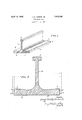
- Fig. 1 is an'isometric view of a portion of a rail in accordance with the present invention
- Fig. 2 is an enlarged transverse section.
- a rail having wheel-receiving surfaces 2 on flange-portions 3.
- A for ordinary usages, it is generally desirable to provide also an upstanding web 4:.
- Such web may be surmounted by ahead 5, .ofconvenient section and contour.
- the outer faces of the flanges 3 have their upper edges 6 retreating inwardly or cut back, as compared with the dimension atthe lower portion 7 of the flangeedge.
- V theamount of such cut-back may vary, but an rounded but 'ingeneral a smooth bevel ispreferable
- the tread surfaces 2 furthermore slope inwardly fromtheir highest'point adjacent the outer edge, and preferably such slope may run smoothly to the base of the web where such is present.
- The; amount of inward slope may vary somewhat, depending upon the particuk 1 lar dutyin view. A proportioning on the order'of af'slope approximating one-fourth of anQ-inch in threeand one-fourth inches is in general desirable for most usages.
- Such a railstructure is thus seento present in its 'transverse-sectional aspects, twin treads sloping inwardly, and outer flangefaces-whose upperedge retreats or'is cut back.
- the plane of the wheel treads w is substantially horizontal transversely ,ofthe. rail, and as initially put into servicea point contact is had.
- metal fiowage tendency occurs from the peening action of the wheels on the tread por- 1 r tions, this is turned to advantage, since such edges cut back and tread surfaces slopin inflowage as occurs is distributively controlled wardly, and wheels having tread sur aces in a form to develop a hard cold-rolled line substantially horizontal transversely thereof. contact surface, superior to the normal steel Signed by me this 9th day of February, in wearing qualities, and such rails are en- 1931.
- Rails in accordance with the present inven- 10 tion may be applied to various situations and conditions where a twin tread is desired, whether on the ground or in an elevated position, the construction being particularly favorable for such usages as crane-tracks and 15 like elevated structures subject to heavy duty.
- a rail of the character described having flanges progressively thickened toward the 30 outer edges and the tread-surfaces sloping inwardly.
- a rail of the character described having its flanges progressively thickened toward the outer edges and the upper outer flange- I I edges cut back and tread surfaces thence 10o sloping inwardly.
- I V v 4 A rail of the character described, having its flanges progressively thickened toward the outer edges and the outer flange-surfaces retreating in substantially the upper half thereof, and having tread surfaces sloping inwardly.
- a rail of the character described having its flanges progressively thickened toward 5 the outer edges and the upper outer fiange- 7 no edges cut back approximately one-sixteenth of an inch at the top.
- a rail of the character described having flanges progressively thickened toward the 50 outer edges and the tread surfaces sloping 116 inwardly approximately one-fourth of an I inch in three and one-fourth inches.
- a rail of the character described having its flanges'progressively thickened toward the 55 outer edges and the outer flange-surfaces re- 120 treating in substantially the upper half approximately one-sixteenth of an inch in seven-thirty-seconds of an inch, and tread surfaces sloping inwardly approximately t one-fourth of an inch in three and one-fourth 120 inches.
Landscapes
- Engineering & Computer Science (AREA)
- Mechanical Engineering (AREA)
- Architecture (AREA)
- Civil Engineering (AREA)
- Structural Engineering (AREA)
- Tires In General (AREA)
Description
STATES UNITE;-
PATENT) OFFICE.
JAMES IBENTLYFORKER, JR., OF CLEVELAND, OHIO, ASSIGNOR TO THE OSBORN-MANU- v FACTURING COMPANY, OFOLEVELAND, OHIO, A CORPORATION OF OHIO TWIN TREAD RAIL Application filed. February 11,,19 31. Serial No.:5.14,947. i
Traction rails in service show peculiar deformative tendencies, some known and some notso well known. The wheel-receiving portions in general exhibit a condition of molecular flowage, the surface portions of the metal undergoing progressive movement from the peening action of the wheels, there being in effecta sort of rolling-mill action upon the portions of metal concerned. Such portions are elongated, both in the longitudinal and transverse directions, and in effect the metalmolecules are in a state of gradual fiow most pronounced at the wheel-receiving surface and tapering off therefrom such that the more remote portions of the rail are correspondingly less alfe'cted, and the most remote portions practically escape. rolling-action in the rail. accentuated at the wheel-receiving surface develops augmented dimensions at the wheel-receivingsurfaces as compared with the progressivelyless-affected metal mass. Particularly, in the case of rails having twin wheel-receiving tread a so surfaces, such peening action develops deformation in the rail, audit is found that such rails develop a bowing. deformation transversely, the tread surfaces being hammered down and outwardly, the molecular movement being greatest at the wheel-receiving faces, while the under-face is substantially unchanged, and the transverse dimension at the upper surface thus becomes greatly'ine creased over the transverse dimension of the lower surface, and a corresponding curling occurs. As a result of study and investigationvof such defects, I have now found, however. that the phenomenon of differential mole-cular flowage in such rail structures may be turned to advantage, controlling its own results, by means of the principle concerned in the present invention. a
To the accomplishmentof the foregoing and related ends, the invention, then, comprises the features hereinafter fully described, and particularly'pointed out inthe claims, the following.descriptioniand the am nexed drawings setting forth in detail certain illustrative embodiments of the invention, these being-indicative, however, of but Such differential a few of the various ways in which the prin},
ciple of the invention may be employed. In said annexed drawings Fig. 1 is an'isometric view of a portion of a rail in accordance with the present invention; and Fig. 2 is an enlarged transverse section.
Referring more particularly to the draw ings, there is shown a rail having wheel-receiving surfaces 2 on flange-portions 3. A For ordinary usages, it is generally desirable to provide also an upstanding web 4:. Preferably, although not necessary, such web may be surmounted by ahead 5, .ofconvenient section and contour. The outer faces of the flanges 3 have their upper edges 6 retreating inwardly or cut back, as compared with the dimension atthe lower portion 7 of the flangeedge. According to particular dutiesin view,
theamount of such cut-back may vary, but an rounded but 'ingeneral a smooth bevel ispreferable, V
' The tread surfaces 2 furthermore slope inwardly fromtheir highest'point adjacent the outer edge, and preferably such slope may run smoothly to the base of the web where such is present. The; amount of inward slope may vary somewhat, depending upon the particuk 1 lar dutyin view. A proportioning on the order'of af'slope approximating one-fourth of anQ-inch in threeand one-fourth inches is in general desirable for most usages.
Such a railstructure is thus seento present in its 'transverse-sectional aspects, twin treads sloping inwardly, and outer flangefaces-whose upperedge retreats or'is cut back. Preferably, the plane of the wheel treads w is substantially horizontal transversely ,ofthe. rail, and as initially put into servicea point contact is had. When now metal fiowage tendency occurs from the peening action of the wheels on the tread por- 1 r tions, this is turned to advantage, since such edges cut back and tread surfaces slopin inflowage as occurs is distributively controlled wardly, and wheels having tread sur aces in a form to develop a hard cold-rolled line substantially horizontal transversely thereof. contact surface, superior to the normal steel Signed by me this 9th day of February, in wearing qualities, and such rails are en- 1931.
abled to stand up under heavy usage corre- JAMES BENTLY FORKER, JR. spondingly more effectively than rails of conventional type heretofore. 7
Rails in accordance with the present inven- 10 tion may be applied to various situations and conditions where a twin tread is desired, whether on the ground or in an elevated position, the construction being particularly favorable for such usages as crane-tracks and 15 like elevated structures subject to heavy duty.
Other modes of applying the principle of the invention may be applied, change being made as regards the details described, provided the means stated in any of the followzo ing claims, or the equivalent of such, be employed.
I therefore particularly point out and distinctly claim as my invention 2-- 1. A rail of the character described, hav- 25 ing its flanges progressively thickened to ward the outer edges and the upper outer flange-edgescut back.
2. A rail of the character described, having flanges progressively thickened toward the 30 outer edges and the tread-surfaces sloping inwardly.
3. A rail of the character described, having its flanges progressively thickened toward the outer edges and the upper outer flange- I I edges cut back and tread surfaces thence 10o sloping inwardly. I V v 4. A rail of the character described, having its flanges progressively thickened toward the outer edges and the outer flange-surfaces retreating in substantially the upper half thereof, and having tread surfaces sloping inwardly.
6. A rail of the character described, having its flanges progressively thickened toward 5 the outer edges and the upper outer fiange- 7 no edges cut back approximately one-sixteenth of an inch at the top. r
6. A rail of the character described, having flanges progressively thickened toward the 50 outer edges and the tread surfaces sloping 116 inwardly approximately one-fourth of an I inch in three and one-fourth inches.
7. A rail of the character described, having its flanges'progressively thickened toward the 55 outer edges and the outer flange-surfaces re- 120 treating in substantially the upper half approximately one-sixteenth of an inch in seven-thirty-seconds of an inch, and tread surfaces sloping inwardly approximately t one-fourth of an inch in three and one-fourth 120 inches. 8. A rail having tread surfaces slopin inwardly, and wheels having tread 'sur aces substantially horizontal transversely thereof. I ll 9. A rail having its upper outer fiangei 30
Priority Applications (1)
| Application Number | Priority Date | Filing Date | Title |
|---|---|---|---|
| US514947A US1853342A (en) | 1931-02-11 | 1931-02-11 | Twin tread rail |
Applications Claiming Priority (1)
| Application Number | Priority Date | Filing Date | Title |
|---|---|---|---|
| US514947A US1853342A (en) | 1931-02-11 | 1931-02-11 | Twin tread rail |
Publications (1)
| Publication Number | Publication Date |
|---|---|
| US1853342A true US1853342A (en) | 1932-04-12 |
Family
ID=24049358
Family Applications (1)
| Application Number | Title | Priority Date | Filing Date |
|---|---|---|---|
| US514947A Expired - Lifetime US1853342A (en) | 1931-02-11 | 1931-02-11 | Twin tread rail |
Country Status (1)
| Country | Link |
|---|---|
| US (1) | US1853342A (en) |
Cited By (1)
| Publication number | Priority date | Publication date | Assignee | Title |
|---|---|---|---|---|
| US3086478A (en) * | 1959-05-25 | 1963-04-23 | Columbus Mckinnon Corp | Trolley track |
-
1931
- 1931-02-11 US US514947A patent/US1853342A/en not_active Expired - Lifetime
Cited By (1)
| Publication number | Priority date | Publication date | Assignee | Title |
|---|---|---|---|---|
| US3086478A (en) * | 1959-05-25 | 1963-04-23 | Columbus Mckinnon Corp | Trolley track |
Similar Documents
| Publication | Publication Date | Title |
|---|---|---|
| DE69708756T2 (en) | tires | |
| DE1291238C2 (en) | VEHICLE TIRES WITH ASYMMETRIC TREAD PROFILING | |
| DE60125005T2 (en) | tire | |
| AT401160B (en) | TIRES WITH A TREAD | |
| DE69728181T2 (en) | SACRED RIBS FOR TIRES WITH IMPROVED WEAR PROPERTIES | |
| DE2029844A1 (en) | tire | |
| DE102010001898A1 (en) | tire | |
| EP3974210A1 (en) | Three-dimensional tire sipe | |
| DE2427197C3 (en) | tire | |
| DE2343591A1 (en) | TIRE | |
| DE2316372A1 (en) | TIRE | |
| US1853342A (en) | Twin tread rail | |
| DE112014004042T5 (en) | tire | |
| DE7606576U1 (en) | TIRE | |
| DE112017003861T5 (en) | tire | |
| US2240866A (en) | Vehicle tire | |
| US1343001A (en) | Street-railroad rail | |
| AT130038B (en) | Tires for wheels. | |
| DE102018221483A1 (en) | Pneumatic tire | |
| US1524728A (en) | Cement-work former | |
| US2214247A (en) | Antiskid tread for running boards and the like | |
| US1355466A (en) | Tramcar | |
| JPH03132404A (en) | Pneumatic tire for heavy load | |
| US505845A (en) | Traction wheel and rail | |
| DE921673C (en) | Pneumatic vehicle tires |