US1853330A - Method of distilling hydrogen halides - Google Patents
Method of distilling hydrogen halides Download PDFInfo
- Publication number
- US1853330A US1853330A US378019A US37801929A US1853330A US 1853330 A US1853330 A US 1853330A US 378019 A US378019 A US 378019A US 37801929 A US37801929 A US 37801929A US 1853330 A US1853330 A US 1853330A
- Authority
- US
- United States
- Prior art keywords
- solution
- temperature
- gases
- distillation
- acid
- Prior art date
- Legal status (The legal status is an assumption and is not a legal conclusion. Google has not performed a legal analysis and makes no representation as to the accuracy of the status listed.)
- Expired - Lifetime
Links
- 238000000034 method Methods 0.000 title description 25
- 239000001257 hydrogen Substances 0.000 title description 3
- 229910052739 hydrogen Inorganic materials 0.000 title description 3
- -1 hydrogen halides Chemical class 0.000 title description 2
- 239000000243 solution Substances 0.000 description 62
- 239000007789 gas Substances 0.000 description 48
- VEXZGXHMUGYJMC-UHFFFAOYSA-N Hydrochloric acid Chemical compound Cl VEXZGXHMUGYJMC-UHFFFAOYSA-N 0.000 description 42
- 239000002253 acid Substances 0.000 description 30
- 238000004821 distillation Methods 0.000 description 29
- 239000000203 mixture Substances 0.000 description 19
- 238000009835 boiling Methods 0.000 description 18
- 238000010438 heat treatment Methods 0.000 description 17
- XLYOFNOQVPJJNP-UHFFFAOYSA-N water Substances O XLYOFNOQVPJJNP-UHFFFAOYSA-N 0.000 description 15
- XEEYBQQBJWHFJM-UHFFFAOYSA-N Iron Chemical compound [Fe] XEEYBQQBJWHFJM-UHFFFAOYSA-N 0.000 description 8
- 239000011260 aqueous acid Substances 0.000 description 6
- 239000000463 material Substances 0.000 description 6
- 238000012856 packing Methods 0.000 description 5
- 239000012535 impurity Substances 0.000 description 4
- 229910052742 iron Inorganic materials 0.000 description 4
- 230000001105 regulatory effect Effects 0.000 description 4
- BMYNFMYTOJXKLE-UHFFFAOYSA-N 3-azaniumyl-2-hydroxypropanoate Chemical compound NCC(O)C(O)=O BMYNFMYTOJXKLE-UHFFFAOYSA-N 0.000 description 3
- 239000012433 hydrogen halide Substances 0.000 description 3
- 229910000039 hydrogen halide Inorganic materials 0.000 description 3
- 238000003303 reheating Methods 0.000 description 3
- 239000007787 solid Substances 0.000 description 3
- TWRXJAOTZQYOKJ-UHFFFAOYSA-L Magnesium chloride Chemical compound [Mg+2].[Cl-].[Cl-] TWRXJAOTZQYOKJ-UHFFFAOYSA-L 0.000 description 2
- 229910000831 Steel Inorganic materials 0.000 description 2
- 239000007864 aqueous solution Substances 0.000 description 2
- 239000000567 combustion gas Substances 0.000 description 2
- 238000010276 construction Methods 0.000 description 2
- FBAFATDZDUQKNH-UHFFFAOYSA-M iron chloride Chemical compound [Cl-].[Fe] FBAFATDZDUQKNH-UHFFFAOYSA-M 0.000 description 2
- 239000007788 liquid Substances 0.000 description 2
- 238000005192 partition Methods 0.000 description 2
- 238000000926 separation method Methods 0.000 description 2
- 239000010959 steel Substances 0.000 description 2
- 241000460034 Erica baccans Species 0.000 description 1
- UFHFLCQGNIYNRP-UHFFFAOYSA-N Hydrogen Chemical class [H][H] UFHFLCQGNIYNRP-UHFFFAOYSA-N 0.000 description 1
- CPELXLSAUQHCOX-UHFFFAOYSA-N Hydrogen bromide Chemical compound Br CPELXLSAUQHCOX-UHFFFAOYSA-N 0.000 description 1
- 230000001174 ascending effect Effects 0.000 description 1
- 230000005540 biological transmission Effects 0.000 description 1
- 239000011449 brick Substances 0.000 description 1
- 238000002485 combustion reaction Methods 0.000 description 1
- 238000009833 condensation Methods 0.000 description 1
- 230000005494 condensation Effects 0.000 description 1
- 230000007797 corrosion Effects 0.000 description 1
- 238000005260 corrosion Methods 0.000 description 1
- 230000007547 defect Effects 0.000 description 1
- 238000007865 diluting Methods 0.000 description 1
- 238000007599 discharging Methods 0.000 description 1
- 238000001704 evaporation Methods 0.000 description 1
- 239000000446 fuel Substances 0.000 description 1
- 239000008246 gaseous mixture Substances 0.000 description 1
- DKAGJZJALZXOOV-UHFFFAOYSA-N hydrate;hydrochloride Chemical compound O.Cl DKAGJZJALZXOOV-UHFFFAOYSA-N 0.000 description 1
- NMCUIPGRVMDVDB-UHFFFAOYSA-L iron dichloride Chemical group Cl[Fe]Cl NMCUIPGRVMDVDB-UHFFFAOYSA-L 0.000 description 1
- 229910001629 magnesium chloride Inorganic materials 0.000 description 1
- 229910052751 metal Inorganic materials 0.000 description 1
- 239000002184 metal Substances 0.000 description 1
- 238000002156 mixing Methods 0.000 description 1
- 238000001556 precipitation Methods 0.000 description 1
- 229920006395 saturated elastomer Polymers 0.000 description 1
- 238000001577 simple distillation Methods 0.000 description 1
- 238000000859 sublimation Methods 0.000 description 1
- 230000008022 sublimation Effects 0.000 description 1
- 238000013022 venting Methods 0.000 description 1
- 239000002699 waste material Substances 0.000 description 1
Images

Classifications
-
- C—CHEMISTRY; METALLURGY
- C01—INORGANIC CHEMISTRY
- C01B—NON-METALLIC ELEMENTS; COMPOUNDS THEREOF; METALLOIDS OR COMPOUNDS THEREOF NOT COVERED BY SUBCLASS C01C
- C01B7/00—Halogens; Halogen acids
- C01B7/01—Chlorine; Hydrogen chloride
- C01B7/07—Purification ; Separation
- C01B7/0706—Purification ; Separation of hydrogen chloride
- C01B7/0712—Purification ; Separation of hydrogen chloride by distillation
Definitions
- The'present invention relates to methods of distilling aqueous'solutions of a hydrogen halide, and particularly to the distillation of aqueous hydrochloric acid solutions.
- -It is an object of oui-,invention to provide a method of distillation employing the sensible heat of a hot gaseous current in direct contact with the acid, thus eliminating altogether the transmission of heat throu h any solid wall with the attendant difficulties and waste of heat.
- Another object is to enable the distillation to be carried out in a larger, more solid and rigid and less destructible type'of apparatus which can be maintained in use for longer periods without need for repair'or replacement than has been possible I with the forms of apparatus heretofore employed.
- our improved method is particularly adapted to large scale operation andmay be utilized equally well for distillinga strong acid gas from an aqueous solution thereoi or for purifying an acid solution containing non-volatile impurities by simple distillation and condensation, ⁇ or for concentrating weakacid solutions.
- Y Y i To the accomplishment of the foregoing and related ends, the invention, then, consists of the method hereinafter fully described and awakeulthly pointed out in the claims, the annexed drawings and the -following descriptionl setting orth'in detail several modes of carrying out the invention, such disclosed modes illustrating, however, but several of various ways in which the principle of the inventionmaybe used.
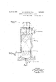
- FIG. 1 is a chart showing liquid and vapor fa u METHOD 0F DISTILLIN'G HYIDROGENV HA-LIDFS i929. serial- No. 318,019.
- Fig. 2 is a vertical cross section of a distillation column of general applicability
- Fig. 3 ' is a cross sectidn of a modified arrangement employing a like column together with associated' means for supplying the hot gas current.
- the solid line curve represents the composition of boiling aqueous solutions of hydrochloric acid plotted against temperatures
- the broken line curve represents the composition of the vapor in equilibrium therewith. It is seen that both curves rise to a common maximum at a temperature of 108 C. and a composition of 20.2 per cent HC1, at which'composition a constant boiling point mixture is produced.
- the solid line curve also constitutes a boiling point temperature curve for aqueous hydrochloric acid solutions of at atmospheric pressure. When the solution is more dilute than the constant boiling point mixture, it may' be concentrated Aup to approximately that point by evaporating, ⁇ in which case 'the distillate consists mostly of y water.
- the heating gases pass out through the exit passage to ether ⁇ with the distillate, and the mixture o HQI as and water vapor in such distillate is diluted by the spent heating gases.
- the heating gases may rec cled in. a closed s stem to conserve the residual heat content t ereof and in such wa that when regular operation is once esta lished the heating gases will have approximately the composition of the distillate, as will be hereinafter further explained.
- 1 represents avertical column or tower constructed of suitable acid resisting material such as sandstone or the like, which ma be in rectangular or other forir., as desire
- the vshaft of the tower 1 is here shown supported upon a base slab 2 having an acid run-off outlet 3 and a trough 4 around the base on the outside to catch leakage which may then be led off through an outlet 5.
- a ating 6 supports aY tower packing 7 compose of acidy a slab or cover 8 through which the aqueous acid to vbe distilled'may 4be introduced in a suitable manner as by the ipes 9 here shown fitted with valves 10 an spra nozzles 11, the latter being dis osed in suc relation to the packing as to istribute the aqueous acid with substantial uniformity thereon.
- a gas inlet 12 is provided near the base of the tower below t e grating 6 and an outlet 13 is similarly disposed in the upper portion of the tower above the packing 7.
- the hot gas current entering the tower through the inlet 12 passes thence upwardly through the packingand finally out through the outlet 13.
- the aqueous acid solution su lied throu h nozzles 11 iows in a multiplicity of smal streams throu h ⁇ the packing in countercurrent to and in irect and unrestricted heat-exchange contact with the ascending current of hot gas.
- the gas urgilreater strength resent invention the proof rings or the like.
- the tower is closed rent is supplied in volume and at a temperature suicient to furnish the heat required for the distillation, a proper adjustment between the su ply of heating ases and rate of flow of fres acid solution o the tower being made so as to maintain the desired operating conditions.
- Fig.'3 shows'a modified arrangement of apparatus, in which a heatin means for the' gasesis combined directly with the distillation column.
- Reference characters 1 to 13, inclusive, therein indicate like apparatus ele.- ments as in Fig. 2.
- An acid supply tank 14 is shown connected by a header pi e 15 from which latera-ls 9 lead to the distri uting sys-l tem in the column..
- A' 'housing 16 con-l structed of lheat retaining materials such as brick, or the like encloses a furnace 17', afan 18, a gas circulating blower 19 and a gas heater 20, here shown as a serpentine coil of4 pi e.
- Blower 19 is connected y the pipe 21 withtlie top of column 1 while pipe coil 20 connects with inlet pipe 12 leading to the base .of column 1.
- VA by-pass pipe 2 2 fitted with a damper or valve 23 connects pipesv 12 -and 21 as shown.
- a baille wall, or partition, 24 divides housing 16 into two compartments, 25
- Fan 18 is disposed so as to draw from the com artment at the left of the bale wall and de iver Vinto compartment 26 at the right.
- Gaseous, liquid or otherfuel is introduced to the furnace 17 through the aperture ,28 and the gasecus products of combustion are circulated within the housing as indicated by the arrows, excess combustion gases being vented at 29.
- the rate of circulation 'of combustion gases in theihfusin and the rate of supply of fuel are contro led to maintain 'the desired temperature of the air bath surrounding the heater 20.
- the temperature drop at cach recurring pass is most advantageousl. limited to about 10 C., or less'.
- the hot furnace gases in comartment 26 ⁇ are employed to heat the circuating gases in coil 20, the latter .gases being -maintained in motion by blower 19in' the direction indicated by the arrows.
- the temperature of the circulating gases entering tower 1 at 12. is ⁇ preferably maintained at about 300 to 325 C.
- the acid solution ltol be'distilled enters the tower through nozzles' i 11 and lflows downwardly through the pack'- ing 7 in countercurrent tothegebertonevaporaable vapor temperature at the top of the tower. As previously explained, such temperature may vary from around 40 to 70 C., when a strong acid gas is being distilled over, to around 100 C., when a weak acid solution is being concentrated, or108 C.
- pipe 21 connecting the top of tower 1 with blower 19 and heater coil 20 is advisedly to ⁇ be made of acid-resisting material, since moist gases drawn from the top of the tower are at a temperature below 140 C.
- byfpass-22 is provided through which by suitable regulation of valve 23, a suicient volume of hot'gases, e. g. at about 300 C., is by-pa'ssed and mixed with the cold gases passing through pipe 21 to raise the temperature ofthe resulting mixture above 140 C.
- distillate under properA temperature control consists almost entirely of water vapor and the very small acid content thereof may be allowed to pass out through a stack for venting the spent heating gases, or, if desired, may be absorbed in water or an alkaline liquor by passing such spent gases through a suitable scrubber tower.
- a reux condenser or dephlegmator may advantageously be employed in conjunction with the distilling column for condensing and returning to the column any excess of aqueous Ivapor which may be entrained with the exit gases.
- HC1 solution discharged from the base of the column which contains whatever "non-volatile impurities were in the original solution, may, if desired, be resaturated with HC1 gas,- and the fortified solution again subjected to distillation.
- the top of the co umn is most advantageously, although not necessarily, maintaine at the constant boiling point temperature, the distillate then consisting of approximately per cent. HC1.
- the method of distillin an aqueous hydrochloric acid solution w ich comprises flowing a distributed stream thereof countercurrent to and in unrestricted heat-exchanve Qcontact with a gaseous current heated initially to a temperature of approximately 300 to 325 C. and regulatin the rate of flow of said solution and sai gaseous current so that the vapors issuing from the distillation zone are at a temperature between ⁇ approximately and 110 C. while a residual solution of a proximately 20 per cent. hydrochloric acid content Hows from said distillation zone. y
- the step which consists in causing a distributed stream of 'such solution to kflow countercurrent to and in direct contact with a hot gaseous current, the latter being supplied at a temperature and in volume suicient to maintain the vapors issuing from the distillation zone at a temperature between 40 and 110 C.
Landscapes
- Chemical & Material Sciences (AREA)
- Organic Chemistry (AREA)
- Inorganic Chemistry (AREA)
- Vaporization, Distillation, Condensation, Sublimation, And Cold Traps (AREA)
Description
April l2, 1932. E. 0,. BARsTow ET AL 1,853,330
METHOD OF DISTILLING HYDROGEN HALIDS v Filed July 1s, 1929 2 sheets-shea 1 ATTORNEY April 12, 1932. K E. o. BARsTow ET AL 1,853,330
METHOD OF-DISTILLING HYDROGEN HALIDES Filed July 1a, 192e 2 sheets-snee; 2-
A 7u ecus Acid Sufff d Irl-9.2
BY 573m JM :ZAM
ATTORNEY Patented Apr. 1932 UNITED STATES, PATENT orf-"lcs nnwm o. nmsrow am) srizliLDoN B. HEATH, or MIDLAND, MICHIGAN, AssIeNoBs 'ro 'rim nowcnEmeAL COMPANY, `or Mmmm), momen, A conroBArIoN or MICHIGAN Application meu .my 1s,
The'present invention relates to methods of distilling aqueous'solutions of a hydrogen halide, and particularly to the distillation of aqueous hydrochloric acid solutions.
The distillationof such aqueous acids has heretofore presented very-serious difliculties owin to their corrosive nature which has limited t e choice of structural materials for the apparatus to a narrow range of acid-proof materials usually mechanically weak, easily lbreakable, and having low conductivity for eat.
-It is an object of oui-,invention to provide a method of distillation employing the sensible heat of a hot gaseous current in direct contact with the acid, thus eliminating altogether the transmission of heat throu h any solid wall with the attendant difficulties and waste of heat. Another object is to enable the distillation to be carried out in a larger, more solid and rigid and less destructible type'of apparatus which can be maintained in use for longer periods without need for repair'or replacement than has been possible I with the forms of apparatus heretofore employed. Our improved method is particularly adapted to large scale operation andmay be utilized equally well for distillinga strong acid gas from an aqueous solution thereoi or for purifying an acid solution containing non-volatile impurities by simple distillation and condensation, `or for concentrating weakacid solutions. Y Y i To the accomplishment of the foregoing and related ends, the invention, then, consists of the method hereinafter fully described and partieulthly pointed out in the claims, the annexed drawings and the -following descriptionl setting orth'in detail several modes of carrying out the invention, such disclosed modes illustrating, however, but several of various ways in which the principle of the inventionmaybe used. A
In said annexed 'drawingsz-L Fig. 1 is a chart showing liquid and vapor fa u METHOD 0F DISTILLIN'G HYIDROGENV HA-LIDFS i929. serial- No. 318,019.
composition curves .for boiling solutions of hydrochloric acid in water at normal atmospheric pressure, 760 mm. Fig. 2 is a vertical cross section of a distillation column of general applicability Fig. 3 'is a cross sectidn of a modified arrangement employing a like column together with associated' means for supplying the hot gas current.
In Fig. 1 lthe solid line curve represents the composition of boiling aqueous solutions of hydrochloric acid plotted against temperatures, and the broken line curve represents the composition of the vapor in equilibrium therewith. It is seen that both curves rise to a common maximum at a temperature of 108 C. and a composition of 20.2 per cent HC1, at which'composition a constant boiling point mixture is produced. The solid line curve also constitutes a boiling point temperature curve for aqueous hydrochloric acid solutions of at atmospheric pressure. When the solution is more dilute than the constant boiling point mixture, it may' be concentrated Aup to approximately that point by evaporating,`in which case 'the distillate consists mostly of y water. On the other hand, stronger solutions than that represented bythe constant boiling point mixture upon distillation give off vapors consisting largely of hydrochloric acid gas untilv the strength of the solution has been reduced to that of the constant boiling point mixture. Continued boiling of such mixture does not result in further concentration or separation of acid and water.
When 'the distillation of an aqueous hydrochloric acid solution is carried out under ractionating conditions in a suitable column or tower, a substantially complete separation of acid and water in the exit vapors may be secured if proper control is exercised over the temperature within the column and of the vapors leaving the top of the column. In the case where a weak solution is being concentratdfthe exit vapor temperature is to improved mode of be maintained at a maximum of about 100 C., for a saturated vapor, orat a somewhat lower temperature for a hydrochloric acid water vapor mixture diluted with other gases corresponding to the partial pressure of such gases. When a solution of than that of the constant boi ing point mixtureis distilled, the temperature of the exit vapors should not exceedabout 70 C. in order to deliver a stron acid gas containing only a relatively smal amount of water vapor, .in which case likewise the presence of diluting gases will necessitate a proportionate lowering of the exit vapory temperature.
In the method of the heat required for the distillation is supplied by a current of hot gas in direct contact with the acid solution flowing throu h the fractionatinv' tower or column. Un er the simplest modeof procedure, the heating gases pass out through the exit passage to ether` with the distillate, and the mixture o HQI as and water vapor in such distillate is diluted by the spent heating gases. By an rocedure, however the heating gases may rec cled in. a closed s stem to conserve the residual heat content t ereof and in such wa that when regular operation is once esta lished the heating gases will have approximately the composition of the distillate, as will be hereinafter further explained.
Referring to Fig. 2, 1 represents avertical column or tower constructed of suitable acid resisting material such as sandstone or the like, which ma be in rectangular or other forir., as desire The vshaft of the tower 1 is here shown supported upon a base slab 2 having an acid run-off outlet 3 and a trough 4 around the base on the outside to catch leakage which may then be led off through an outlet 5. Within the tower, a ating 6 supports aY tower packing 7 compose of acidy a slab or cover 8 through which the aqueous acid to vbe distilled'may 4be introduced in a suitable manner as by the ipes 9 here shown fitted with valves 10 an spra nozzles 11, the latter being dis osed in suc relation to the packing as to istribute the aqueous acid with substantial uniformity thereon. A gas inlet 12 is provided near the base of the tower below t e grating 6 and an outlet 13 is similarly disposed in the upper portion of the tower above the packing 7.
The hot gas current entering the tower through the inlet 12 passes thence upwardly through the packingand finally out through the outlet 13. The aqueous acid solution su lied throu h nozzles 11 iows in a multiplicity of smal streams throu h`the packing in countercurrent to and in irect and unrestricted heat-exchange contact with the ascending current of hot gas. `The gas curglreater strength resent invention the proof rings or the like. The tower is closed rent is supplied in volume and at a temperature suicient to furnish the heat required for the distillation, a proper adjustment between the su ply of heating ases and rate of flow of fres acid solution o the tower being made so as to maintain the desired operating conditions. The absence of indirect heatin means for boiling the acid solution in a sti located below the column, or of means for transmitting heat through a partition wall separating the solution from the heatin gases is a vital feature of our improve method'. All of the heat required for distillation is provided as sensible heat of the en tering gas stream, thereby removing the most serious defects and drawbacks of methods heretofore practiced. V
Fig.'3 shows'a modified arrangement of apparatus, in which a heatin means for the' gasesis combined directly with the distillation column. Reference characters 1 to 13, inclusive, therein indicate like apparatus ele.- ments as in Fig. 2. An acid supply tank 14 is shown connected by a header pi e 15 from which latera-ls 9 lead to the distri uting sys-l tem in the column.. A' 'housing 16 con-l structed of lheat retaining materials such as brick, or the like encloses a furnace 17', afan 18, a gas circulating blower 19 and a gas heater 20, here shown as a serpentine coil of4 pi e. Blower 19 is connected y the pipe 21 withtlie top of column 1 while pipe coil 20 connects with inlet pipe 12 leading to the base .of column 1. VA by-pass pipe 2 2 fitted with a damper or valve 23 connects pipesv 12 -and 21 as shown. A baille wall, or partition, 24 divides housing 16 into two compartments, 25
and 26, leaving a passage 27 communicatingbetween said compartments. Fan 18 is disposed so as to draw from the com artment at the left of the bale wall and de iver Vinto compartment 26 at the right. Gaseous, liquid or otherfuel is introduced to the furnace 17 through the aperture ,28 and the gasecus products of combustion are circulated within the housing as indicated by the arrows, excess combustion gases being vented at 29. The rate of circulation 'of combustion gases in theihfusin and the rate of supply of fuel are contro led to maintain 'the desired temperature of the air bath surrounding the heater 20. In practice the temperature drop at cach recurring pass is most advantageousl. limited to about 10 C., or less'.
In operation the hot furnace gases in comartment 26` are employed to heat the circuating gases in coil 20, the latter .gases being -maintained in motion by blower 19in' the direction indicated by the arrows. The temperature of the circulating gases entering tower 1 at 12. is `preferably maintained at about 300 to 325 C. The acid solution ltol be'distilled enters the tower through nozzles' i 11 and lflows downwardly through the pack'- ing 7 in countercurrent tothe gasestevaporaable vapor temperature at the top of the tower. As previously explained, such temperature may vary from around 40 to 70 C., when a strong acid gas is being distilled over, to around 100 C., when a weak acid solution is being concentrated, or108 C. when a constant boiling point mixture of hydrchloric acid and water vapor is being distilled at normal atmospheric pressure. A portion l of the gases or vapors from thetop of the tower sufcient to maintain the circulation ot' the heating gases is returned through pipe 21 by means of blower'19, reheated in coil 20 and again 'delivered to the base of the tower through inlet 12. The remainin portion of distillation 'gases is with rawn through exit passage 13 to a suitable condens; ino' system not shown.
nA commencing operation, the as passages Aof the circulating system being ed chiefly with air, such air is heated and conducted to inlet 12 whence it riser` throu htower 1 and intermixes with the acid an water vapors given oit by the distillation. A portion of llili the air accompanied by some acid and water vapor is recycled through the heating coil, while the remainder issues from the tower mixed with the distillation products. By continued operation, naturally, the original air in the system is'eventually completely vented with the exit gases, and the circulating gasesv then consistof acid gas or water vapor or a mixture thereoitv corresponding to the distillation product.
Y For ease and economyof construction, as well as to create the most advantageous conditions for heat transfer in the heating coil, the latter and most` of the Aaccessory piping and equipment are to be constructed-of iron or steel. -Although hydrochloric acid, particularly when mlxed with water, is highly corrosive to iron at ordinary temperatures,
wehave found that if the acid gas, or m1xture l thereof with water vapor, is maintained at`a temperature above about 140 C. and below 325 C., there will be little or no material attack on an iron surface exposed thereto. Such temperature limits comprise roughly the range within which a solution of iron chloride will be evaporated to dryness in the gas current and yet below a temperature whereat any substantial sublimation of iron chloride will occur. It is probable that within the temperature limits approximately as stated a surface film of iron chloride forms which protects the metal from further atw tack. In the apparatus illustrated in Fig. 3,
As just described, we are thus enabled to distill aqueous hydrochloric acid solutions of any strength by a continuous procedure, introducing such solution into the upper part of the fractionating columnfortower and 4withdrawing a solution of approximately constant boiling point composition. 1. e. approximately 20 per cent. HC1, from the base of the tower. When the distillation is conducted without recirculation of heating gases as in apparatus illustrated in Fig. 2, the distillate leaving the column is accompanied by the heating gases. In the case where a weak acid solution is to be concentrated to about 20 per cent. strength, such distillate under properA temperature control consists almost entirely of water vapor and the very small acid content thereof may be allowed to pass out through a stack for venting the spent heating gases, or, if desired, may be absorbed in water or an alkaline liquor by passing such spent gases through a suitable scrubber tower. 1
llt an acid solution of more than 20 per cent. strength is to be distilled to produce a' strong- HC1 gas, it is preferable to employ recirculation of the heating gases in an apparatus similar or equivalent to that illustrated in Fig. .3. ln such apparatus, after a condition of constant vapor composition has been vestablished,lthe heating gases will have the of a strong acid gas containing 95 per cent. or
more HC1. At times a reux condenser or dephlegmator may advantageously be employed in conjunction with the distilling column for condensing and returning to the column any excess of aqueous Ivapor which may be entrained with the exit gases. The
strong acid gas produced maybe employed as such in further operations, as, for example, in dehydrating magnesium chloride, or it may be absorbed in water to produce ajpure concentrated acidl solution. The 20u-per cent. HC1 solution discharged from the base of the column," which contains whatever "non-volatile impurities were in the original solution, may, if desired, be resaturated with HC1 gas,- and the fortified solution again subjected to distillation. I When the distillation is carried out simply for the purpose of purifyin an aqueous HCl solution, the top of the co umn is most advantageously, although not necessarily, maintaine at the constant boiling point temperature, the distillate then consisting of approximately per cent. HC1. Under such procedure it is advisable not to distill all of the acid solution fed to the column, the rate of feedand of flow of heating' gases being so adjusted that a suiiicient resldual solution to hold substantially all of the nonvolatile impurities dissolved therein may be discharged from the base of the column. By so operating the precipitation of solid impurities in the column packing is prevented and consequently danger of obstructing o1 sto ping the interstices and passages in the pac mg is avoided. By varying the exit vapor tem erature, however, a stronger aqueous aci distillate may be produced, but in such case an equivalent amount of 20 per cent. acid solution will be discharged from the base of the column.
By similar procedure solutions of hydrobromic acid may likewise be distilled, making due allowance for the boiling point temperatures of such solutions. The constant boiling oint solution contains 44 per cent. HBr and ils at 126 C. Consequently operation with such solutions would be conducted so as to maintain a maximum temperature of 126 C. in the vapor space at the top of the claims or the equivalent of such stated step or steps be emp yed. 1
We therefore` particularly point out and distinctly claim as our invention 1. The method of distillin an aqueous hydrochloric acid solution w ich comprises flowing a distributed stream thereof countercurrent to and in unrestricted heat-exchanve Qcontact with a gaseous current heated initially to a temperature of approximately 300 to 325 C. and regulatin the rate of flow of said solution and sai gaseous current so that the vapors issuing from the distillation zone are at a temperature between` approximately and 110 C. while a residual solution of a proximately 20 per cent. hydrochloric acid content Hows from said distillation zone. y
2. The method. ofdistilling an aqueous 'hydrochloric acid solution which comprises 'flowing a distributed stream thereof countercurrent to and in unrestricted heat-exchange contact with a geasous current heated initially to a temperature of approximately 300 to 325 C. and regulating the rate of ow of said solution an said gaseous current so that the vapors issuing from the distillation zone are at a temperature between approximately hydrochloric acid solution which comprises v fiowing a distributed stream thereof countercurrent to and in unrestricted heat-exchan e contact with a gaseous current heated initial y to a temperature of approximately 300 -to 325 C. and regulating the rate-of flow of said solution and said gaseous current so that the vapors issuing from Athe distillation zone are at a temperature between approximately 40 and 110 C. while a residual solution of approximately 20 per cent. hydrochloric acid content flows from said distillation zone, withdrawing a portion of said vapors, mixing.
therewith a portionv of said heated gaseous' current, which has been by-passed from tlie main body thereof before the latter is contacted with said solution, so that the temperature of the resultant gaseous mixture is maintained above about 140 C., reheating said mixture to approximately 300 to 325 C. and returning the reheated gases to the first step for the hot gaseous current therein.
4.-' In a method of distilling an aqueous 'hydrochloric acid solution, the step which consists in contacting the same under fractionating conditions with a hot gaseous current at a temperature and in volume sufficient to maintain the vapors issuing from the distillation zone at a temperature between 40 and 110 C.
5. In a method of distilling an aqueous hydrochloric acid solution, the step which consists in causing a distributed stream of 'such solution to kflow countercurrent to and in direct contact with a hot gaseous current, the latter being supplied at a temperature and in volume suicient to maintain the vapors issuing from the distillation zone at a temperature between 40 and 110 C.
6. The method of distillingI an aqueous hy drochloric acid solution, which comprises causing a distributed stream of such solution to flow countercurrent to and in direct contact with a` hot gaseous current, the latter being supplied at a temperature and in volume suilicient to maintain the vapors issuing "from the distillation zone at a tem erature between 40 and 110 C., withdrawing a portion of said vapors, reheating the same and returning the reheated vapors to the distillation step for the hot gaseous current therein. Y l
7. The method of distilling a concentrated hydrochloric acid solution to produce a strong hydrochloric acid gas,` which comprises {iowloe4 Lacasse i ing a distributed stream thereof countercur-V rent to and in direct contact with a gaseous current heated initially to a temperature of approximately 300 to 325 C., regulating the rate of flow of said solution and said gaseous current so that the vapors issuing from the distillation zone are at a temperature between approximately 40 and 7 0 C. and discharging a residual acid solution of approximately per cent strength. v
8. The method of distilling a concentrated i hydrochloric acid solution to produce a strong ing a portion of said vapors and returning the reheated vapors to the distillation ste for the hot gaseous current therein.
9. The method of distilling a concentrated hydrochloric acid solution to produce a strong hydrochloric acidgas,whichcomprisesflowing a distributed stream thereof countercurrent to and in direct contact with a gaseous curi rent heated initially to a temperature of ap'- proximately 300 to 325 C., regulating the a hot gaseous current at a tem rature and in volume sutlicient to vaporize t e same and to maintain the exit vapors from the heating zone at a temperature between about 40 C.
and the boiling point of the aqueous acid l solution of constant boiling point withdrawing a portion of said vapors, reheating the same and returning the reheated vapors to the distillation step for the hot gaseous current thsiein'db h d fJl igne y us t is 11 ay o u y, 1929.
EDWIN O. BARSTOW. SHELDON B. HEATH.
rate of flow of said solution and said gaseous current so that the vapors issuing from the distillation zone are at a temperature betweenv approximately 40 and 70 C., discharging a residual acid solution of approximately 20 per cent strength, withdrawing a portion of said vapors, mixing therewith a portion of said heated gaseous current, which has been by-passed from the main body thereof before the latter is contacted with saidv solution, so that the temperature of the resultant gaseous mixture is-maintained above about 140 C., reheating said mixture to approximately 300 to 325 1C. and returning the reheated gases to the distillation step for the hot gaseous current therein.
10. In a method of distilling an aqueous hydrogen halide solution of the class consisting of hydrobromic acid and hydrochloric acid, the step which consists in contacting such solution under fractionating conditions with a hot gaseous current atatemperature and in volume suiiicient to vaporize the same and to maintain theexit vapors from the heatin zone at a temperature between about 40 and the boiling point of the aqueousacid solution of constant boiling oint. 11. In a method of distilling an aqueous hydrogen halide solution of the class consisting of hydrobromic acid and hydrochloric acid the steps which consist in contacting such solution under fractionating conditions with
Priority Applications (1)
| Application Number | Priority Date | Filing Date | Title |
|---|---|---|---|
| US378019A US1853330A (en) | 1929-07-13 | 1929-07-13 | Method of distilling hydrogen halides |
Applications Claiming Priority (1)
| Application Number | Priority Date | Filing Date | Title |
|---|---|---|---|
| US378019A US1853330A (en) | 1929-07-13 | 1929-07-13 | Method of distilling hydrogen halides |
Publications (1)
| Publication Number | Publication Date |
|---|---|
| US1853330A true US1853330A (en) | 1932-04-12 |
Family
ID=23491397
Family Applications (1)
| Application Number | Title | Priority Date | Filing Date |
|---|---|---|---|
| US378019A Expired - Lifetime US1853330A (en) | 1929-07-13 | 1929-07-13 | Method of distilling hydrogen halides |
Country Status (1)
| Country | Link |
|---|---|
| US (1) | US1853330A (en) |
Cited By (9)
| Publication number | Priority date | Publication date | Assignee | Title |
|---|---|---|---|---|
| US2428221A (en) * | 1942-02-06 | 1947-09-30 | Walker Brothers | Pickling process |
| US2475752A (en) * | 1945-06-01 | 1949-07-12 | Hercules Powder Co Ltd | Hydrogen chloride manufacture |
| US3860492A (en) * | 1973-06-27 | 1975-01-14 | Jr Alvin Lowi | Liquid separation system |
| US4129425A (en) * | 1977-07-18 | 1978-12-12 | The United States Of America As Represented By The United States Department Of Energy | Gas-absorption process |
| US5174865A (en) * | 1991-01-25 | 1992-12-29 | Dow Deutschland Inc. | Process for purifying crude hydrochloric acid |
| US9115467B2 (en) | 2010-08-01 | 2015-08-25 | Virdia, Inc. | Methods and systems for solvent purification |
| US9410216B2 (en) | 2010-06-26 | 2016-08-09 | Virdia, Inc. | Sugar mixtures and methods for production and use thereof |
| US9476106B2 (en) | 2010-06-28 | 2016-10-25 | Virdia, Inc. | Methods and systems for processing a sucrose crop and sugar mixtures |
| US9512495B2 (en) | 2011-04-07 | 2016-12-06 | Virdia, Inc. | Lignocellulose conversion processes and products |
-
1929
- 1929-07-13 US US378019A patent/US1853330A/en not_active Expired - Lifetime
Cited By (17)
| Publication number | Priority date | Publication date | Assignee | Title |
|---|---|---|---|---|
| US2428221A (en) * | 1942-02-06 | 1947-09-30 | Walker Brothers | Pickling process |
| US2475752A (en) * | 1945-06-01 | 1949-07-12 | Hercules Powder Co Ltd | Hydrogen chloride manufacture |
| US3860492A (en) * | 1973-06-27 | 1975-01-14 | Jr Alvin Lowi | Liquid separation system |
| US4129425A (en) * | 1977-07-18 | 1978-12-12 | The United States Of America As Represented By The United States Department Of Energy | Gas-absorption process |
| US5174865A (en) * | 1991-01-25 | 1992-12-29 | Dow Deutschland Inc. | Process for purifying crude hydrochloric acid |
| DE4201494A1 (en) * | 1991-01-25 | 1993-02-18 | Dow Chemical Co | METHOD FOR PURIFYING RAW SALT ACID |
| US10752878B2 (en) | 2010-06-26 | 2020-08-25 | Virdia, Inc. | Sugar mixtures and methods for production and use thereof |
| US9410216B2 (en) | 2010-06-26 | 2016-08-09 | Virdia, Inc. | Sugar mixtures and methods for production and use thereof |
| US9963673B2 (en) | 2010-06-26 | 2018-05-08 | Virdia, Inc. | Sugar mixtures and methods for production and use thereof |
| US9476106B2 (en) | 2010-06-28 | 2016-10-25 | Virdia, Inc. | Methods and systems for processing a sucrose crop and sugar mixtures |
| US10760138B2 (en) | 2010-06-28 | 2020-09-01 | Virdia, Inc. | Methods and systems for processing a sucrose crop and sugar mixtures |
| US9714482B2 (en) | 2010-08-01 | 2017-07-25 | Virdia, Inc. | Methods and systems for solvent purification |
| US9115467B2 (en) | 2010-08-01 | 2015-08-25 | Virdia, Inc. | Methods and systems for solvent purification |
| US11242650B2 (en) | 2010-08-01 | 2022-02-08 | Virdia, Llc | Methods and systems for solvent purification |
| US9512495B2 (en) | 2011-04-07 | 2016-12-06 | Virdia, Inc. | Lignocellulose conversion processes and products |
| US10876178B2 (en) | 2011-04-07 | 2020-12-29 | Virdia, Inc. | Lignocellulosic conversion processes and products |
| US11667981B2 (en) | 2011-04-07 | 2023-06-06 | Virdia, Llc | Lignocellulosic conversion processes and products |
Similar Documents
| Publication | Publication Date | Title |
|---|---|---|
| US1906467A (en) | Distilling hydrochloric acid | |
| US1853330A (en) | Method of distilling hydrogen halides | |
| US3635664A (en) | REGENERATION OF HYDROCHLORIC ACID PICKLING WASTE BY H{11 SO{11 {0 ADDITION, DISTILLATION AND FeSO{11 {0 Precipitation | |
| US3192128A (en) | Process for purifying aqueous hydrochloric acid | |
| US1892652A (en) | Preparation of strong hydrogen halide gas | |
| US2124729A (en) | Concentrating acid solutions | |
| US2770295A (en) | Concentrating process and apparatus | |
| US2096855A (en) | Manufacture of ferric chloride | |
| JPS6327283B2 (en) | ||
| US2368901A (en) | Ammonium sulphate production | |
| US1897996A (en) | Preparation of strong hydrogen halide gas | |
| US838195A (en) | Process of distillation. | |
| US1902801A (en) | Continuous process of preparing liquid bromine | |
| US4046822A (en) | Method for recovering ethylene values | |
| SU548205A3 (en) | The method of obtaining trichloromethanesulfonyl chloride | |
| US236940A (en) | Jules l | |
| US1988759A (en) | Heat recovery system | |
| US2199797A (en) | Purification of chlorine | |
| US3434948A (en) | Method for chlorine cooling and brine heating | |
| US939980A (en) | Process of making acetates. | |
| US2818413A (en) | Continuous process for the production of furfural and acetic acid from vegetative material | |
| US2880146A (en) | Apparatus for evaporating fluids | |
| US2552425A (en) | Method of producing vinyl chloride | |
| HU186283B (en) | Process and apparatus for producing pure chlorocyan | |
| US2021791A (en) | Process for producing hydrated ferric chloride |