US1853327A - Lever stall - Google Patents
Lever stall Download PDFInfo
- Publication number
- US1853327A US1853327A US491391A US49139130A US1853327A US 1853327 A US1853327 A US 1853327A US 491391 A US491391 A US 491391A US 49139130 A US49139130 A US 49139130A US 1853327 A US1853327 A US 1853327A
- Authority
- US
- United States
- Prior art keywords
- stanchions
- rails
- lever
- pair
- members
- Prior art date
- Legal status (The legal status is an assumption and is not a legal conclusion. Google has not performed a legal analysis and makes no representation as to the accuracy of the status listed.)
- Expired - Lifetime
Links
Images
Classifications
-
- A—HUMAN NECESSITIES
- A01—AGRICULTURE; FORESTRY; ANIMAL HUSBANDRY; HUNTING; TRAPPING; FISHING
- A01K—ANIMAL HUSBANDRY; AVICULTURE; APICULTURE; PISCICULTURE; FISHING; REARING OR BREEDING ANIMALS, NOT OTHERWISE PROVIDED FOR; NEW BREEDS OF ANIMALS
- A01K1/00—Housing animals; Equipment therefor
- A01K1/06—Devices for fastening animals, e.g. halters, toggles, neck-bars or chain fastenings
- A01K1/062—Neck-bars, e.g. neck collars
Definitions
- 'My invention relates to improvements in lever stalls, and the object of myimprovement is to supply an apparatus of this char.- acter for cow barns and elsewhere, wherein one or more pairs of movably connected stanchion members may be easily manually operated as desired in opening and closing one or more pairs of stanchions, while one or more other pairs of stanchions in the assemblage are dissociated and placedin locked position.
- Another improvement consists in providing means for relatively opening and closing both of the members ofa pair ofstanchions .16 simultaneously and through a predetermined I scope of movement.
- Another improvement consists in providing releasable means forlocking the stanchions or one or more of the pairs thereof in isolation from the others, when it is desired to operate such others in the opening thereof.
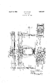
- FIG. 1 is a front elevation of a lever stall equipped with my improvements, and with parts broken away or. shown in .partial section.
- '2 is atop plan of saiddevice with parts broken away.
- Fig. 3 is an enlarged view, in detail, with parts broken awayor shown in horizontal section, of the means-employed for swinging the stanchion members to and from each other, and as engaged'rele asably to an'operating rod.
- Fig. 4 is a like enlarged detail view, showing the arcuate.
- the numerals 5 and 6 denote respectively the like but reversed members of a pair. of stanchions, which are at their lower ends overlapped and hinged for to and froswinging movements on a pintle-bolt 7, the stanchions. having on one a depending eye 8 connected by chains 9 to a floor fixture 10 a to restrict the, playv of the stanchions.
- Theustanchions 5 and 6 are preferably chanr the parts 13 may be hollow and when their fiat faces are approximated, together having a circular contour.
- the hooked parts 14 are circularly grooved in their spacing from the parts 13, permitting the hooks 14 to slide aroundthe semicircular'parts of cross members 17 rigidly connected between or a part of slide members 18 mountedin the hollows between flanges of spaced horizontal rails 2 of an elevated track fixed on the tops of longitudinally spaced posts 1 and secured thereto by bolts 4.
- the members 17 have their hollows facing, and when the stanchions are closed together as in Figs. land 4,.are coaxial with the stanchion terminals 13. Conse quently the pair ofstanchions 5 and 6 may be rocked laterallyas one to conform to'movementsof an. animal whose neck'is inclosed between them. Stop screws or blocks as at 15 in the rails 2 project inwardly toward each other to stop the terminals 13 in closed positions, so that they may not swing beyond a medial position of suspension: e
- the numeral 50 denotes a cross bar fixed across the tops of the rails 2 by screws or other means and'having a medial upright pivot-pin 49 on which, is medially pivoted a rock-bar 23 with end portions of even lengths.
- To the outer ends of the rock-bar 23 are pivotedat24 and 25 respectively endsof link-bars 26 and 27.
- Each pair ofslide devices 17 has rigid cross connections 20 on which are fixed upright pivot-pins 21 and 22 respectively on which are pivoted the abutting ends of the links 27 and 26.
- the numeral 33 denotes a manually operable arm of angular shape which is pivoted at its angle at 32 to the track rails 2.
- the outer part of this arm when the stanchions are closed, depends alongside a terminal post 1, and is received in a position beyond its dead center in a stop offset bracket 35 on a plate 34 secured to the post.
- the opposite part of the arm 33 is pivoted at 31 to an end of a link-bar 30 which has its opposite end pivoted at 29 to a longitudinal rod 28.
- a catch finger 42 is mounted rockingly and nonslidingly, having a pair of spaced sleeves 45 on either side of a fixed clamp 44 on the rod 28.
- This finger is positioned on the rod appropriately to have a terminal aperture 43 therein receive and engage the pivot-pin 22 on one of the slides 18.
- this catch 43 is swung over to release said pin 22, and the stanchions may be locked in closed position by engaging the catch 48 with the pivot-pin 21.
- a plurality of pairs of such stanchions are provided along the extended rails 2. All of these may be swung open and closed, when the catches 48 are disengaged and the other catches 42 engaged. All but one or more pairs of stanchions may be thus operated, when the others are disconnected from the rod 28 but connected lockingly to the track by the catches 48.
- An arm 37 may be terminally pivoted to the rod 28 at 36, and pivoted at its other end to both an arm 39 and a stop member 41, the arm 39 being pivoted a its other end to a postl, so that the rod 28 may move the stop 41 as shown in dotted lines to an extended position to bar an animal "from pushing between a post 1 and the next adjacent stanchions.
- a lever stall an elevated track, a pair of movably connected stanchions positioned thereunder with approximated upper ends having terminal hooks extending oppositely outwardly in the plane of the stanchions, like but reversed slide devices movable to and fro along said track and each having an arcuate cross connection transverse to the track, with hollows opening inwardly, the terminal hooks of said stanchions being hung movably on said cross connections respectively to ride laterally thereon when the stanchions are rocked laterally to and fro, and operating means connected to both said slide devices to swing the stanchions to and from each other.
- a lever stall an elevated track, a pair of movably connected stanchions positioned thereunder with approximated upper ends having terminal hooks, like but reversed slide devices movable to and fro along said track and each having an arcuate cross member, the hollows of the cross members opening inwardly toward each other, the terminal hooks of said stanchions being hung loosely on said cross members to ride thereon, when the stanchions are rocked laterally, and operating means connected to both of the slide devices, for moving them to and from each other simultaneously for a limited amount of separation of the stanchions in opening or closing them.
- an elevated track consisting of laterally spaced rails, a pair of stanchions thereunder hinged together at their lower ends and having approximated upper ends provided with terminal hooks, slide devices mounted between said rails and supported thereon to be moved, to and fro thereon, said devices each consisting of spaced side plates having transverse arcuate cross connections reversed in position relative to each other, the terminal hooks of the stanchions being mounted upon said arcuate members to ride therealong when the stanchions are rocked laterally, and operating means movably connected to both slide devices, manually operable, to slide them to and fro to open or close the stanchions, simultaneously, said operating means including a member movable across a dead center to hold the stanchions in either of said positions.
- an elevated track consisting of laterally spaced rails, a pair of hinged stanchions positioned thereunder, slides mounted between said rails and supported thereon, said slides having like but reversed arcuate cross connections respectively, the upper ends of the stanchions being shaped to ride suspensively upon the cross connections when the stanchions are rocked laterally, operating means for simultaneously shifta ing said slides to and fro and releasably connected thereto, and an engaging arm mounted on the track to releasably lock said slides with the stanchions closed together, when said operating means is released from the slides.
- an elevated track consisting of laterally spaced rails, a pair of hinged stanchions positioned thereunder, slides mounted on and between the rails having like but relatively reversed arcuate transverse connections, the upper parts of the stanchions having like oppositely directed hooks to ride upon said arcuate connections respectively when the stanchions are rocked laterally, a rock-bar medially pivotally supported upon said rails to rock transversely relative thereto midway of said cross connections, like links pivotally mounted at one end of each on said slides respectively and having their other ends respectively pivotally connected to the opposite ends of said rock-bar, operating means having a releasable connection with one of said slides, and a catch movably connected to one of said rails having engaging means thereon for engaging the other slide releasably when the operating means is released from the first mentioned slide.
- elevated supports like but reversed arcuate members mounted on said supports to slide to and from each other, andja pair of stanchions positioned below said supports and. having their upper terminations shaped as counterparts to ride engagingly and rockingly upon said arcuate members witha common axis of rotation relative thereto and with each other.
Landscapes
- Life Sciences & Earth Sciences (AREA)
- Zoology (AREA)
- Environmental Sciences (AREA)
- Animal Husbandry (AREA)
- Biodiversity & Conservation Biology (AREA)
- Catching Or Destruction (AREA)
Description
' April 12, 1932.
W. O. WILLE LEVER STALL Filed 001:, 27, 1930 INVENTOR PVQ: ga r' 0. W1; Z Ze,
' ATTORNEY Patented Apr. 12, .1932 r UNITED) STATES PATENT oFiFicE WALTER WILLIE, OF WATERLOO, IOWA, ASSIGNOR TO CLAY EQUIPMENT GORPORA.
'IION, OF CEDAR 'FALLS, IOWA LEVER STALL applicationfiledflctober 27, 1930. Serial No. 491,391.
'My invention relates to improvements in lever stalls, and the object of myimprovement is to supply an apparatus of this char.- acter for cow barns and elsewhere, wherein one or more pairs of movably connected stanchion members may be easily manually operated as desired in opening and closing one or more pairs of stanchions, while one or more other pairs of stanchions in the assemblage are dissociated and placedin locked position. I
. Another improvement consists in providing means for relatively opening and closing both of the members ofa pair ofstanchions .16 simultaneously and through a predetermined I scope of movement.
Another improvement consists in providing releasable means forlocking the stanchions or one or more of the pairs thereof in isolation from the others, when it is desired to operate such others in the opening thereof.
These objects I have accomplished in actual practice by the means which arehereinafter described and claimed, and which are illustrated in the accompanying drawings, in which 1 is a front elevation of a lever stall equipped with my improvements, and with parts broken away or. shown in .partial section. '2 is atop plan of saiddevice with parts broken away. Fig. 3 is an enlarged view, in detail, with parts broken awayor shown in horizontal section, of the means-employed for swinging the stanchion members to and from each other, and as engaged'rele asably to an'operating rod. Fig. 4 is a like enlarged detail view, showing the arcuate. cross connections of slide plates on which are suspensively mounted the hooked upper terminals of hinged stanchions, the means for swinging the stanchions not shown. 7 In the apparatus shown, the numerals 5 and 6 denote respectively the like but reversed members of a pair. of stanchions, which are at their lower ends overlapped and hinged for to and froswinging movements on a pintle-bolt 7, the stanchions. having on one a depending eye 8 connected by chains 9 to a floor fixture 10 a to restrict the, playv of the stanchions. 3i Theustanchions 5 and 6 are preferably chanr the parts 13 may be hollow and when their fiat faces are approximated, together having a circular contour. The hooked parts 14 are circularly grooved in their spacing from the parts 13, permitting the hooks 14 to slide aroundthe semicircular'parts of cross members 17 rigidly connected between or a part of slide members 18 mountedin the hollows between flanges of spaced horizontal rails 2 of an elevated track fixed on the tops of longitudinally spaced posts 1 and secured thereto by bolts 4. The members 17 have their hollows facing, and when the stanchions are closed together as in Figs. land 4,.are coaxial with the stanchion terminals 13. Conse quently the pair ofstanchions 5 and 6 may be rocked laterallyas one to conform to'movementsof an. animal whose neck'is inclosed between them. Stop screws or blocks as at 15 in the rails 2 project inwardly toward each other to stop the terminals 13 in closed positions, so that they may not swing beyond a medial position of suspension: e
I have adopted the following described mechanism for manually operating the stan- 80 chionsto swing them to and from each other. Referring to Figs. 2 and 3, the numeral 50 denotes a cross bar fixed across the tops of the rails 2 by screws or other means and'having a medial upright pivot-pin 49 on which, is medially pivoted a rock-bar 23 with end portions of even lengths. To the outer ends of the rock-bar 23 are pivotedat24 and 25 respectively endsof link-bars 26 and 27. Each pair ofslide devices 17 has rigid cross connections 20 on which are fixed upright pivot-pins 21 and 22 respectively on which are pivoted the abutting ends of the links 27 and 26.
Whenthe stanchions Band 6 are in closed position, they are suspended coaxially beneath the pivot-pin 49. As thus. closed, a catch48 pivoted at. 47 mounted in apertures of lugs 46 on a rail 2 has an apertured finger 48 which may engage the pivot-pin 21 to lock the operating means shown in Figs. 3 and 2. 100
Referring to said Fig. 1, the numeral 33 denotes a manually operable arm of angular shape which is pivoted at its angle at 32 to the track rails 2. The outer part of this arm when the stanchions are closed, depends alongside a terminal post 1, and is received in a position beyond its dead center in a stop offset bracket 35 on a plate 34 secured to the post. The opposite part of the arm 33 is pivoted at 31 to an end of a link-bar 30 which has its opposite end pivoted at 29 to a longitudinal rod 28. On the rod 28, as shown in Fig. 3, a catch finger 42 is mounted rockingly and nonslidingly, having a pair of spaced sleeves 45 on either side of a fixed clamp 44 on the rod 28. This finger is positioned on the rod appropriately to have a terminal aperture 43 therein receive and engage the pivot-pin 22 on one of the slides 18. When it is desired to not open the stanchions of a pair, this catch 43 is swung over to release said pin 22, and the stanchions may be locked in closed position by engaging the catch 48 with the pivot-pin 21. However, in many lever stalls, a plurality of pairs of such stanchions are provided along the extended rails 2. All of these may be swung open and closed, when the catches 48 are disengaged and the other catches 42 engaged. All but one or more pairs of stanchions may be thus operated, when the others are disconnected from the rod 28 but connected lockingly to the track by the catches 48. This arrangement saves time, and prevents loosening of one or more animals, when the other animals are released. As both stanchions 5 and 6 are opened swingingly from each other, a large interspace is furnished, so that an animal with long horns may be accommodated.
An arm 37 may be terminally pivoted to the rod 28 at 36, and pivoted at its other end to both an arm 39 and a stop member 41, the arm 39 being pivoted a its other end to a postl, so that the rod 28 may move the stop 41 as shown in dotted lines to an extended position to bar an animal "from pushing between a post 1 and the next adjacent stanchions.
Having described my invention, what I claim as new, and desire to secure by Letters Patent, is:
1. In a lever stall, an elevated track, a pair of movably connected stanchions positioned thereunder with approximated upper ends having terminal hooks extending oppositely outwardly in the plane of the stanchions, like but reversed slide devices movable to and fro along said track and each having an arcuate cross connection transverse to the track, with hollows opening inwardly, the terminal hooks of said stanchions being hung movably on said cross connections respectively to ride laterally thereon when the stanchions are rocked laterally to and fro, and operating means connected to both said slide devices to swing the stanchions to and from each other.
2. In a lever stall, an elevated track, a pair of movably connected stanchions positioned thereunder with approximated upper ends having terminal hooks, like but reversed slide devices movable to and fro along said track and each having an arcuate cross member, the hollows of the cross members opening inwardly toward each other, the terminal hooks of said stanchions being hung loosely on said cross members to ride thereon, when the stanchions are rocked laterally, and operating means connected to both of the slide devices, for moving them to and from each other simultaneously for a limited amount of separation of the stanchions in opening or closing them.
3. In a lever stall, an elevated track consisting of laterally spaced rails, a pair of stanchions thereunder hinged together at their lower ends and having approximated upper ends provided with terminal hooks, slide devices mounted between said rails and supported thereon to be moved, to and fro thereon, said devices each consisting of spaced side plates having transverse arcuate cross connections reversed in position relative to each other, the terminal hooks of the stanchions being mounted upon said arcuate members to ride therealong when the stanchions are rocked laterally, and operating means movably connected to both slide devices, manually operable, to slide them to and fro to open or close the stanchions, simultaneously, said operating means including a member movable across a dead center to hold the stanchions in either of said positions.
4. In a lever stall, an elevated track consisting of laterally spaced rails, a pair of hinged stanchions positioned thereunder, slides mounted between said rails and supported thereon, said slides having like but reversed arcuate cross connections respectively, the upper ends of the stanchions being shaped to ride suspensively upon the cross connections when the stanchions are rocked laterally, operating means for simultaneously shifta ing said slides to and fro and releasably connected thereto, and an engaging arm mounted on the track to releasably lock said slides with the stanchions closed together, when said operating means is released from the slides.
5. In a lever stall, an elevated track consisting of laterally spaced rails, a pair of hinged stanchions positioned thereunder, slides mounted on and between the rails having like but relatively reversed arcuate transverse connections, the upper parts of the stanchions having like oppositely directed hooks to ride upon said arcuate connections respectively when the stanchions are rocked laterally, a rock-bar medially pivotally supported upon said rails to rock transversely relative thereto midway of said cross connections, like links pivotally mounted at one end of each on said slides respectively and having their other ends respectively pivotally connected to the opposite ends of said rock-bar, operating means having a releasable connection with one of said slides, and a catch movably connected to one of said rails having engaging means thereon for engaging the other slide releasably when the operating means is released from the first mentioned slide.
6. In a device of the character described, elevated supports, like but reversed arcuate members mounted on said supports to slide to and from each other, andja pair of stanchions positioned below said supports and. having their upper terminations shaped as counterparts to ride engagingly and rockingly upon said arcuate members witha common axis of rotation relative thereto and with each other.
In testimony whereof I aifix my signature.
WALTER O. WILLE.
Priority Applications (1)
| Application Number | Priority Date | Filing Date | Title |
|---|---|---|---|
| US491391A US1853327A (en) | 1930-10-27 | 1930-10-27 | Lever stall |
Applications Claiming Priority (1)
| Application Number | Priority Date | Filing Date | Title |
|---|---|---|---|
| US491391A US1853327A (en) | 1930-10-27 | 1930-10-27 | Lever stall |
Publications (1)
| Publication Number | Publication Date |
|---|---|
| US1853327A true US1853327A (en) | 1932-04-12 |
Family
ID=23952016
Family Applications (1)
| Application Number | Title | Priority Date | Filing Date |
|---|---|---|---|
| US491391A Expired - Lifetime US1853327A (en) | 1930-10-27 | 1930-10-27 | Lever stall |
Country Status (1)
| Country | Link |
|---|---|
| US (1) | US1853327A (en) |
Cited By (1)
| Publication number | Priority date | Publication date | Assignee | Title |
|---|---|---|---|---|
| US2506112A (en) * | 1946-07-29 | 1950-05-02 | Simonson Ben | Stanchion |
-
1930
- 1930-10-27 US US491391A patent/US1853327A/en not_active Expired - Lifetime
Cited By (1)
| Publication number | Priority date | Publication date | Assignee | Title |
|---|---|---|---|---|
| US2506112A (en) * | 1946-07-29 | 1950-05-02 | Simonson Ben | Stanchion |
Similar Documents
| Publication | Publication Date | Title |
|---|---|---|
| US2396928A (en) | Branding and dehorning chute | |
| US1853327A (en) | Lever stall | |
| US2650567A (en) | Cattle chute | |
| US1612608A (en) | Animal trap | |
| US2999480A (en) | Livestock chute gate | |
| US3024766A (en) | Parlor stall | |
| US1867722A (en) | Lever stall | |
| US3623456A (en) | Chute gate | |
| US1487977A (en) | Stanchion and operating table for animals | |
| US2148551A (en) | Portable stock holder | |
| US2126593A (en) | Animal holding chute | |
| US2229588A (en) | Stock restraining device | |
| US1021523A (en) | Device for slaughtering animals. | |
| US1784890A (en) | Cattle stanchion | |
| US1340357A (en) | Hog-breeding crate | |
| US1337925A (en) | Animal-stanchion | |
| US1161802A (en) | Cattle-stanchion. | |
| US1364405A (en) | Adjustable cattle-stanchion | |
| US1900676A (en) | Animal stanchion | |
| US1818552A (en) | Animal stall | |
| GB738971A (en) | Improvements in or relating to ties, yokes and the like for animals | |
| US1843328A (en) | Cattle-stanchion | |
| US641480A (en) | Cattle-stanchion. | |
| US1916953A (en) | Cattle hitch | |
| US1790577A (en) | ferris |