US1853324A - Vulcanizing apparatus - Google Patents
Vulcanizing apparatus Download PDFInfo
- Publication number
- US1853324A US1853324A US267230A US26723028A US1853324A US 1853324 A US1853324 A US 1853324A US 267230 A US267230 A US 267230A US 26723028 A US26723028 A US 26723028A US 1853324 A US1853324 A US 1853324A
- Authority
- US
- United States
- Prior art keywords
- shell
- casing
- pneumatic tire
- head
- heating unit
- Prior art date
- Legal status (The legal status is an assumption and is not a legal conclusion. Google has not performed a legal analysis and makes no representation as to the accuracy of the status listed.)
- Expired - Lifetime
Links
- 238000010438 heat treatment Methods 0.000 description 14
- 238000000465 moulding Methods 0.000 description 4
- 101100379079 Emericella variicolor andA gene Proteins 0.000 description 1
- 239000011324 bead Substances 0.000 description 1
- 230000000295 complement effect Effects 0.000 description 1
- 238000001816 cooling Methods 0.000 description 1
- 230000003247 decreasing effect Effects 0.000 description 1
- 239000012530 fluid Substances 0.000 description 1
- 239000000463 material Substances 0.000 description 1
- 238000012986 modification Methods 0.000 description 1
- 230000004048 modification Effects 0.000 description 1
- 238000004073 vulcanization Methods 0.000 description 1
Images
Classifications
-
- B—PERFORMING OPERATIONS; TRANSPORTING
- B29—WORKING OF PLASTICS; WORKING OF SUBSTANCES IN A PLASTIC STATE IN GENERAL
- B29C—SHAPING OR JOINING OF PLASTICS; SHAPING OF MATERIAL IN A PLASTIC STATE, NOT OTHERWISE PROVIDED FOR; AFTER-TREATMENT OF THE SHAPED PRODUCTS, e.g. REPAIRING
- B29C73/00—Repairing of articles made from plastics or substances in a plastic state, e.g. of articles shaped or produced by using techniques covered by this subclass or subclass B29D
- B29C73/24—Apparatus or accessories not otherwise provided for
- B29C73/30—Apparatus or accessories not otherwise provided for for local pressing or local heating
- B29C73/305—Apparatus or accessories not otherwise provided for for local pressing or local heating specially adapted for toroidal articles, e.g. tyres
-
- B—PERFORMING OPERATIONS; TRANSPORTING
- B29—WORKING OF PLASTICS; WORKING OF SUBSTANCES IN A PLASTIC STATE IN GENERAL
- B29C—SHAPING OR JOINING OF PLASTICS; SHAPING OF MATERIAL IN A PLASTIC STATE, NOT OTHERWISE PROVIDED FOR; AFTER-TREATMENT OF THE SHAPED PRODUCTS, e.g. REPAIRING
- B29C35/00—Heating, cooling or curing, e.g. crosslinking or vulcanising; Apparatus therefor
- B29C35/02—Heating or curing, e.g. crosslinking or vulcanizing during moulding, e.g. in a mould
- B29C35/04—Heating or curing, e.g. crosslinking or vulcanizing during moulding, e.g. in a mould using liquids, gas or steam
- B29C35/049—Heating or curing, e.g. crosslinking or vulcanizing during moulding, e.g. in a mould using liquids, gas or steam using steam or damp
-
- B—PERFORMING OPERATIONS; TRANSPORTING
- B29—WORKING OF PLASTICS; WORKING OF SUBSTANCES IN A PLASTIC STATE IN GENERAL
- B29L—INDEXING SCHEME ASSOCIATED WITH SUBCLASS B29C, RELATING TO PARTICULAR ARTICLES
- B29L2030/00—Pneumatic or solid tyres or parts thereof
Definitions
- rIhis invention relates generally to apparatus for vulcamzmg products composed of rubber and it has particular relation to an 1D that of the apparatus heretofore generally f
- the shell and casing are disposed within the employed.
- Another object of the invention is to provide a vulcanizing apparatus for repairing pneumatic tire casings, in which a heating element is employed continuously for curingy tires without the necessity of its being rendered inoperative during the period of time in which the vulcanizing heat is dissipated by the casings.
- known apparatus employed for vulcanizing-the repaired portions of pneumatic tire casings embodied a chambered unit to which steam was supplied for vulcanizing the rubber employed in repairing the casing. Atthe end of a predetermined period of time the steamwas shut off and the apparatus was permitted to cool until the casing safely could be removed therefrom. During this period of time the apparatus was not only incapable of being employed for curing the repaired portions of other pneumatic tire casings, but a great amount of heat was entirely wasted, owing to the necessity for cooling the entire apparatus.
- This embodiment of the invention comprises a heating unit, to whichsteam is applied continuously, having a pluralityy of shells or molding elements which are disposed successively in heat-conducting relationship to the heating unit.
- a repaired portion of a pneumatic tire casing is positioned within yone of the shells and secured rigidly therein by suitable clamping devices.
- the heating unit and the heat supplied to the latter is conducted to the casing through the shell.
- the shell and the casing are removed from the heating unit and another 192s. serial No. 267,230.
- the shell and casing are yinserted therein.
- the first-mentioned casing is permitted to cool under pressure Within its shell fora predetermined period of time, after which it is removed therefrom and the shell again employed as hereinbefcre described.
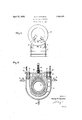
- Fig. 1 is a side elevational view of an apparatus embodying one form of the invention, having a pneumatic tire casing inserted therein;
- Fig. 2 is a cross-sectional view taken substantially on lineII-II of Fig. 1.
- an arcuately formed heating unit 10v having a 'substantially U-shape cross-sectional coniguration is supported by bars 11 that are secured by bolts 12, to an upper portion of a fabricated supporting frame 13.
- the interior of the heating runit 10 is chambered, as indicated at 14, for receiving steam or other suitable heating Huid through conduits 16 and 17, which are connected at the upper portions of the chamber.
- a Aconduit 18 ⁇ communicating with a lower portion of the chamber 14 provides means for exhausting the heating fluid from the chamber.y
- An arcuate shell 19 registers in heat-conducting relationship with a depression within the central portion of the heating unit 10.
- The, head 26 is secured within an upper portion of the shell 19 by engagement with a spaced pair of circular blocks 28 and 29 that are journaled on the lower ends of a pair of set screws 31 and 32.
- the Set screws 31 and 32 are screwthreaded into openings formed within lugs 33 disposedintermediate the ends of bars 34.
- Machine screws 36 projecting through openings formed adjacent the opposite ends of the bars 34, are screw-threaded in openings formed in the upper surfaces of the pairs of lugs 21 and 22.
- Stud bolts 37 disposed vertically in the upper edges of the heating unit 10, project through openings formed in the ends of the bars 34, which are located beyond the openings for receiving the screws 36, and are adapted to receive nuts 3S upon the ends thereof, above the bars.
- a portion of a pneumatic tire casing 39 which previously has been repaired by the employment of uncured rubber, is inserted Within the shell 19.
- An airbag 41 having a valve stem 42, is y positioned Within the portion of the casing 39 which is arranged Within the interior of the shell 19.
- the sections 23 and 24 of the head 26 then are inserted in the upper portion of the shell 19 above the bead portions of the casing 39, and the bars 34 are secured in position by the manipulation of the machine screws 36.
- the head 26 is then forced down- Wardly by the manipulation of the screws 31 and 32 until the easing is secured rigidly Within the shell 19.
- An air hose (not shown), thereafter, is associated operatively With the valve stem 42 of the airbag 41 and the latter is iniated to a predetermined pressure.
- the unit is inserted within the heating unit 1() and the nuts 38 are tightened slightly in order to insure efficient heatconducting contact between the shell 19 and the heater 10.
- the latter and 40 the shell 19 are removed from the heating unit 10 and another casing secured Within a shell, as hereinbefore described, is inserted therein.
- the first mentioned Casing 39 is permitted to remain Within the shell 19 until its temperature has been reduced substantially and the vulcanization of the repaired portion of the casing is completed.
- the airbag 31 then is deflated and the head 26 and easing 39 are removed from the shell 19, which is thereafter employed in curing the repaired portion of other pneumatic tire casings, as hereinbefore described.
- a vulcanizing apparatus comprising a molding shell, a heater associated conductive-ly With a portion of the shell, means for compressing a portion of a pneumatic ltirecasing Within the shell, andA means for removably securing the last-mentioned'meuns tothe shell and the heater.
- a vuleanizing apparatus comprising ⁇ *a molding shell, a heater associated conductive-90 ly With a portion of the shell, a headv means for securing the head to the shell, means for compressing a portion of a pneumatic tire casing Within the shell, and means associated with the aforementioned means for securing the head and the shell to the heater.
- a vulcanizing 4apparatus comprising a molding shell, a heater associated conductively With a portion of the shell, a head, means for removably securing the head to the shell, .100 means vfor compressing a portion of a--pneumatic tire casing Within the shell, and means associated with the aforementionedr means for removably-securing the head Vand ythe shell vto the heater rigidly.
Landscapes
- Engineering & Computer Science (AREA)
- Mechanical Engineering (AREA)
- Heating, Cooling, Or Curing Plastics Or The Like In General (AREA)
Description
April 12, 1932. G, M, SPROWLS 1,853,324
VULCANIZING APPARATUS Filed April 4.. 1928 George M. Spowls.
Patented Apr. 12,` 1932 HQE PAT-ENT o GEORGE M. SPROWLS, OF AKRON, OHIO, ASSIGNORTO THE GOODYEAR TIRE & RUBBER COMPANY, OF AKRON,r OHIO, A CORPORATION OF OHIO vULcANIzINe- APPARATUS Application tiled April 4,
rIhis invention relates generally to apparatus for vulcamzmg products composed of rubber and it has particular relation to an 1D that of the apparatus heretofore generally f The shell and casing are disposed within the employed.
Another object of the invention is to provide a vulcanizing apparatus for repairing pneumatic tire casings, in which a heating element is employed continuously for curingy tires without the necessity of its being rendered inoperative during the period of time in which the vulcanizing heat is dissipated by the casings.
Prior to the invention, known apparatus, employed for vulcanizing-the repaired portions of pneumatic tire casings embodied a chambered unit to which steam was supplied for vulcanizing the rubber employed in repairing the casing. Atthe end of a predetermined period of time the steamwas shut off and the apparatus was permitted to cool until the casing safely could be removed therefrom. During this period of time the apparatus was not only incapable of being employed for curing the repaired portions of other pneumatic tire casings, but a great amount of heat was entirely wasted, owing to the necessity for cooling the entire apparatus.
This embodiment of the invention comprises a heating unit, to whichsteam is applied continuously, having a pluralityy of shells or molding elements which are disposed successively in heat-conducting relationship to the heating unit. A repaired portion of a pneumatic tire casing is positioned within yone of the shells and secured rigidly therein by suitable clamping devices.
heating unit and the heat supplied to the latter is conducted to the casing through the shell. When the repaired portion of the tire casing has had a sufficient qantity of heat applied thereto, the shell and the casing are removed from the heating unit and another 192s. serial No. 267,230.
shell and casing are yinserted therein. The first-mentioned casing is permitted to cool under pressure Within its shell fora predetermined period of time, after which it is removed therefrom and the shell again employed as hereinbefcre described.
Forv abetter understanding of the invention, reference may now be had to the accompanying drawings, forming a part of the specification, in which:
Fig. 1 is a side elevational view of an apparatus embodying one form of the invention, having a pneumatic tire casing inserted therein; and
Fig. 2 is a cross-sectional view taken substantially on lineII-II of Fig. 1.
In practicing the invention, an arcuately formed heating unit 10v having a 'substantially U-shape cross-sectional coniguration, is supported by bars 11 that are secured by bolts 12, to an upper portion of a fabricated supporting frame 13. The interior of the heating runit 10 is chambered, as indicated at 14, for receiving steam or other suitable heating Huid through conduits 16 and 17, which are connected at the upper portions of the chamber. A Aconduit 18 `communicating with a lower portion of the chamber 14 provides means for exhausting the heating fluid from the chamber.y An arcuate shell 19 registers in heat-conducting relationship with a depression within the central portion of the heating unit 10. Spaced pairs of lugs 21 and 22, formed externally with respect to the shell 19, adjacent the opposite extremities thereof, are adapted to be received by complementary recesses formed in upper portions of the unit 10. Arcuate sections 23 and 24, constituting a head 26, are removably secured together by dowel pins 27 screw-threaded into an edge of the section 24 and slidably engaging openings disposed oppositely thereto in the corresponding edge of the section 23. The, head 26 is secured within an upper portion of the shell 19 by engagement with a spaced pair of circular blocks 28 and 29 that are journaled on the lower ends of a pair of set screws 31 and 32. The Set screws 31 and 32 are screwthreaded into openings formed within lugs 33 disposedintermediate the ends of bars 34.
In the operation of the apparatus, ,a portion of a pneumatic tire casing 39, which previously has been repaired by the employment of uncured rubber, is inserted Within the shell 19. An airbag 41, having a valve stem 42, is y positioned Within the portion of the casing 39 which is arranged Within the interior of the shell 19. The sections 23 and 24 of the head 26 then are inserted in the upper portion of the shell 19 above the bead portions of the casing 39, and the bars 34 are secured in position by the manipulation of the machine screws 36. The head 26 is then forced down- Wardly by the manipulation of the screws 31 and 32 until the easing is secured rigidly Within the shell 19. An air hose (not shown), thereafter, is associated operatively With the valve stem 42 of the airbag 41 and the latter is iniated to a predetermined pressure. When the casing 39 andthe shell 19 are thus assembled, the unit is inserted within the heating unit 1() and the nuts 38 are tightened slightly in order to insure efficient heatconducting contact between the shell 19 and the heater 10. After a predetermined time has elapsed, during which heat from the ksteam within the steam chamber 14 cures the reaired portion of the casing 39, the latter and 40 the shell 19 are removed from the heating unit 10 and another casing secured Within a shell, as hereinbefore described, is inserted therein. The first mentioned Casing 39 is permitted to remain Within the shell 19 until its temperature has been reduced substantially and the vulcanization of the repaired portion of the casing is completed. The airbag 31 then is deflated and the head 26 and easing 39 are removed from the shell 19, which is thereafter employed in curing the repaired portion of other pneumatic tire casings, as hereinbefore described.
From the foregoing description, it is apparent that pneumatic tire casings may be repaired more economically bythe employment of the .apparatus embodying the invention 'than Was possible when employing the apparatus heretofore known. Since the heating unit is employed continuously* in supplying heat to the unvulcanized portions of pneumatic tire easings and is not intermittently cooled as in the apparatus heretofore employed, a very material saving of heat energy results. b casing and shell are removed from the heater Owing to the fact that the tire While the heat embodied therein is dissipated, the time required for the curing operation is greatly decreased, since the shell is directly exposed to the atmosphere, Whereas formerly, it was conducted at a very low rate through the heater.
Although I have illustrated but vthe preferred form which the invention may assume, and have described that form in detail, it Will be apparent to those skilled inthe art that the invention'is not so limited but that various modifications may be made therein Without departing from the spirit of the invention or from the scope of the appended claims.
What I claim is:
1. A vulcanizing apparatus comprising a molding shell, a heater associated conductive-ly With a portion of the shell, means for compressing a portion of a pneumatic ltirecasing Within the shell, andA means for removably securing the last-mentioned'meuns tothe shell and the heater.
2. A vuleanizing apparatus comprising `*a molding shell, a heater associated conductive-90 ly With a portion of the shell, a headv means for securing the head to the shell, means for compressing a portion of a pneumatic tire casing Within the shell, and means associated with the aforementioned means for securing the head and the shell to the heater.
3. A vulcanizing 4apparatus comprising a molding shell, a heater associated conductively With a portion of the shell, a head, means for removably securing the head to the shell, .100 means vfor compressing a portion of a--pneumatic tire casing Within the shell, and means associated with the aforementionedr means for removably-securing the head Vand ythe shell vto the heater rigidly. f
In .witness whereof, I have hereunto signed my name.
Signed .at Akron, in the county ofSummit and State of Ohio, U. S. A., this 3rd dayof April, 1928. 11o
GEORGE M. SPROWLS.
Priority Applications (1)
| Application Number | Priority Date | Filing Date | Title |
|---|---|---|---|
| US267230A US1853324A (en) | 1928-04-04 | 1928-04-04 | Vulcanizing apparatus |
Applications Claiming Priority (1)
| Application Number | Priority Date | Filing Date | Title |
|---|---|---|---|
| US267230A US1853324A (en) | 1928-04-04 | 1928-04-04 | Vulcanizing apparatus |
Publications (1)
| Publication Number | Publication Date |
|---|---|
| US1853324A true US1853324A (en) | 1932-04-12 |
Family
ID=23017881
Family Applications (1)
| Application Number | Title | Priority Date | Filing Date |
|---|---|---|---|
| US267230A Expired - Lifetime US1853324A (en) | 1928-04-04 | 1928-04-04 | Vulcanizing apparatus |
Country Status (1)
| Country | Link |
|---|---|
| US (1) | US1853324A (en) |
-
1928
- 1928-04-04 US US267230A patent/US1853324A/en not_active Expired - Lifetime
Similar Documents
| Publication | Publication Date | Title |
|---|---|---|
| US2421099A (en) | Recapping of tires | |
| US2421097A (en) | Process and apparatus for repair of tires | |
| US2066265A (en) | Method of curing tires | |
| US2421096A (en) | Process and apparatus for repairing tires | |
| US1426672A (en) | Retread for tires and method of making them | |
| US1923736A (en) | Vulcanizing device | |
| US1853324A (en) | Vulcanizing apparatus | |
| US2670499A (en) | Connecting and sealing means for curing bags | |
| US2335878A (en) | Tire vulcanizing machine | |
| US2871514A (en) | Equipment used to vulcanize or recap vehicle tires | |
| US2421098A (en) | Repair of tires | |
| US2663905A (en) | Superimposed multiple cavity mold | |
| US2574171A (en) | Tire side wall mold | |
| US1500700A (en) | Method of vulcanizing | |
| US2606342A (en) | Vulcanizing apparatus for retreading tires | |
| US1623677A (en) | Vulcanizing apparatus | |
| US1445428A (en) | Tire-retreading device | |
| US2320778A (en) | Tire vulcanizing apparatus | |
| US2370241A (en) | Combination spot vulcanizer | |
| US2903741A (en) | Tire vulcanizing equipment | |
| US1842124A (en) | Tire repair vulcanizer | |
| US2266720A (en) | Tire repair vulcanizer | |
| US1429831A (en) | Tire mold | |
| US1619231A (en) | Vulcanizer | |
| US1643493A (en) | Tire vulcanizer |