US1853217A - Electrical filter system - Google Patents
Electrical filter system Download PDFInfo
- Publication number
- US1853217A US1853217A US330994A US33099429A US1853217A US 1853217 A US1853217 A US 1853217A US 330994 A US330994 A US 330994A US 33099429 A US33099429 A US 33099429A US 1853217 A US1853217 A US 1853217A
- Authority
- US
- United States
- Prior art keywords
- current
- circuits
- source
- filter
- filtration
- Prior art date
- Legal status (The legal status is an assumption and is not a legal conclusion. Google has not performed a legal analysis and makes no representation as to the accuracy of the status listed.)
- Expired - Lifetime
Links
- 238000001914 filtration Methods 0.000 description 15
- 238000004804 winding Methods 0.000 description 6
- 230000003321 amplification Effects 0.000 description 5
- 238000003199 nucleic acid amplification method Methods 0.000 description 5
- 230000008878 coupling Effects 0.000 description 3
- 238000010168 coupling process Methods 0.000 description 3
- 238000005859 coupling reaction Methods 0.000 description 3
- 238000010438 heat treatment Methods 0.000 description 3
- 230000000694 effects Effects 0.000 description 2
- 230000003472 neutralizing effect Effects 0.000 description 2
- 238000005513 bias potential Methods 0.000 description 1
- 230000001808 coupling effect Effects 0.000 description 1
- 230000004907 flux Effects 0.000 description 1
- 238000004519 manufacturing process Methods 0.000 description 1
- 238000006386 neutralization reaction Methods 0.000 description 1
- 230000010355 oscillation Effects 0.000 description 1
- 230000002265 prevention Effects 0.000 description 1
Images
Classifications
-
- H—ELECTRICITY
- H02—GENERATION; CONVERSION OR DISTRIBUTION OF ELECTRIC POWER
- H02M—APPARATUS FOR CONVERSION BETWEEN AC AND AC, BETWEEN AC AND DC, OR BETWEEN DC AND DC, AND FOR USE WITH MAINS OR SIMILAR POWER SUPPLY SYSTEMS; CONVERSION OF DC OR AC INPUT POWER INTO SURGE OUTPUT POWER; CONTROL OR REGULATION THEREOF
- H02M1/00—Details of apparatus for conversion
- H02M1/14—Arrangements for reducing ripples from DC input or output
- H02M1/143—Arrangements for reducing ripples from DC input or output using compensating arrangements
Definitions
- the present invention relates to electrical filter systems, and'in particular such a system forsupplying two or more loads from a single source of supply of periodically fluctuating uni-directional current.
- a particular object is to supply the plate circuits of two or'more vacuum tubes with filtered uni-'directional'current from a S111- gle rectifier ofalternating current at differcut voltages with. the economical use of of the loss ofcurr'ent through filter material while keepinghum production low, as is required in commerciallyfacceptable radio'broadcast receivers.
- vfiltration is accomplished before division takes place.
- all of the plate current fora radio receiver having a power amplifier requiring say '200 volts, other amplifiers requiring say 100 volts, and a detector requiring say 40 volts is first filtered and then divided, as by a tapped resistor termed a voltage divider shunted across theroutput of the filter circuit, for distribution to the plate circuits of thes'everal vacuum tubes.
- This practice requires a large amount of filter apparatus vandresults in a lossof some of the expensively filtered current by way of the shunted voltage divider. Since it is well known that the-more current passing through a filter or,
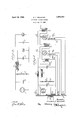
- FIG. 1 diagrammatically.illustrates the invention ina generalized form.
- Fig. 2- illustrates the invention employed as afiltersystem to supply the plate circuits ofthree elec- .7
- trode vacuum tubes connected in tandem in an amplifying system from rectified alternating current.
- the device S is-any source of periodically fluctuating unidirectional ourrent, preferably shunted by a condenser C of capacity suitable forenergy storage.v
- a shunt resistance B provides for dividing the potential of the source into one orm-ore components of lesser potential thantotal, as by connection of a circuit to the point a in the resistance as shown.
- the circuit including the inductance L is shown supplying a load IE at highest potential, andfiltration is had by the inductance of L aided by the capacity of shunt condenser 0
- the circuit including inductance'L supplies a load IE at lower potential, and the current is filtered by the inductance ofL aided by shuntcondenser C ployed for useful work is subjected to ahigh degree of filtration, the loss current through voltage divider resistance R not encountering the filter elements at all.
- the system is also adapted to coupling the coilsL and L as by winding in opposite directions on the same core, to cause the alternating current components in the two coils to oppose, to improve filtration by neutral- In this way only current emizing the fluctuating efiects.
- a winding provides for the magnetic field due to the direct current component in one circuit opposing the magnetic field due to the direct current component in the other circuit, thus aiding in avoiding magnetic saturation in the magnetic core, and
- a transformer T'supplied from an alternating current source through a primary winding P has secondary winding S for heating the filament of a full wave recti 'fier tube RT, whose anodes are energized by secondary winding S the rectified cur-,-
- the system supplies the plate circuits of threeelectrode vacuum tubes VT and VT connected in cascade through audio transformer T as loads corresponding to E and E respectively in Fig. 1.
- Transformer T indicates an audio frequency input to the cascade amplifier, and transformer T indicates an output, as to a loud speaker 'or other translating device.
- the amplifying system may be extended, as by including a detector and one or more stages of radio frequency amplification for a usual type of radio receiver.
- Secondary windings S and S are shown to supply the filaments of tubes VT and VT respectively with raw alternating current for heating in accordance with general practice, but any form of filament heating may be used, this not being a feature of the present invention.
- Resistances R and R connected to cross-connected filament resistances K and K respectively provide for developing grid bias potentials for tubes VT and VT respectively, and are further shown to have signal-shunting condensers C and G all in accordance with general practice, and not directly forming features of the present invention, so that other arrangements suitable for accomplishing the same results may be substituted.
- Tube VT may be a power amplifier and thus supplied with high and full potential current through coil L filtration of coil L being aided by shunt condenser C
- Tube VT is shown supplied with current at lesser potential through connection of coil L to point a on resistance R, filtration being accomplished by coil L with the aid of shunt condenser C
- the loss current through voltage divider resistance It does not enter the filter system and, at the same time, the filter condensers C and 0;, provide low impedance paths for the signal currents of tubes VT and VT respectively.
- the impedance of coils L and L cooperate with these condensers to prevent signal currents from reaching resistance R, and therefore located as it is in the present invention this resistance has negligible eflect in producing feed-back coupling.
- the coils L and L may be coupled to introduce neutralizing effects as between both the alternating and direct current component effects. Since thecurrent in L may be large compared to the current in L L may have more turns in order to more nearly equalize the ampereturn relation of the two coils.
- the values of condensers C and G can be selected to aid in improving the relation of the alternating current ampere turns in Itwill be further noted that fluctuations in the plate circuit of tube VT will be transferred to tube VT by way of transformer T and amplified before encountering the fluctuations in the plate circuit of VT If transformer T is so poled as to transfer the fluctuations to VT in phase to oppose the fluctuations in the plate circuit of VT further neutralization can be had, but in view of the amplification it is desirable to have the fluctuations in VT less than in VT by a factor substantiallyequal to the amplification factor of VT For this reason it is desirable to filter the current supplied to theplate of VT to higher degree than that supplied to VT or if poor filtration is had for tube VT to make the filtration for VT correspondingly worse in proportion to the amplification.
- a current supply and filter system the combination of a source of uni-directional periodically fluctuating current, a plurality of work circuits, a resistance in shunt to said source to which said work circuits are connected at points different in potential,
- a current supplyand filter system the combination of a source of uni-directional periodically fluctuating current, a plurality of work circuits, means for impressing from said source currents at different potentials upon said work circuits, and inductance coils in two of said circuits so inductively related that the fields generated therein by the alternating current components are opposed.
- a current supply and filter system for energizing the plate circuits of said tubes comprising a source of uni-directional periodically fluctuating current, a resistance in shunt to said source to which the plate circuits of said tubes are connected at points different in potential, and means associated with said plate circuits for filtering the currents delivered thereto, said means including inductance coils in two of said circuits so therein are opposed.
- a current supply and filter system for energizing the anode circuits of said devices comprising a source of unidirectional fluctuating current, a resistance element shunted across said source to which the anode circuits of said devices are connected at points different in potential and means associated with said anode circuits for filtering the currents delivered thereto, said means including inductance coils in twojof said circuits wound around the same core and so inductively related that the fields generated therein are opposed whereby fluctuating current effects in each of said circuits are substantially neutralized and magnetic saturation of said core is substantially prevented.
Landscapes
- Engineering & Computer Science (AREA)
- Power Engineering (AREA)
- Amplifiers (AREA)
Description
p i 1932- B. F. MIESSNER 1,853,217
ELECTRICAL FILTER SYSTEM Filed Jan. 8, 1929 'HIIIlUII Patented Apr. 12, .1932 i UNITED-STATES} PATENT OFFICE,
IBENJ'AMINF. MIESSNER, OF SHORT HILLS, NEW J ERSEY,IASSIGNOR, BY MESN E ASSIGN- Y IIYIENTS, TQ RADIO CORPORATION" 'OF AMERICA, OF NEW YORK, N. Y., A CORPORA- TIONOF DELAWARE ELECTRICAL FILTER SYSTEM Application filed January 8, 1929. Serial No. 330,994.
The present invention relates to electrical filter systems, and'in particular such a system forsupplying two or more loads from a single source of supply of periodically fluctuating uni-directional current.
A particular object is to supply the plate circuits of two or'more vacuum tubes with filtered uni-'directional'current from a S111- gle rectifier ofalternating current at differcut voltages with. the economical use of of the loss ofcurr'ent through filter material while keepinghum production low, as is required in commerciallyfacceptable radio'broadcast receivers.
It is a feature of my present invention that I divide the rectified or other unsteady currentinto the number of .difierent components desired for distribution to work cir-,
cuits before filtration is undertaken. In present practice vfiltration is accomplished before division takes place. For example, all of the plate current fora radio receiver having a power amplifier requiring say '200 volts, other amplifiers requiring say 100 volts, and a detector requiring say 40 volts, is first filtered and then divided, as by a tapped resistor termed a voltage divider shunted across theroutput of the filter circuit, for distribution to the plate circuits of thes'everal vacuum tubes. This practice requires a large amount of filter apparatus vandresults in a lossof some of the expensively filtered current by way of the shunted voltage divider. Since it is well known that the-more current passing through a filter or,
in other words, the greater the load thereon,
the less complete is the filtration by reason the voltage divider, so-that the residual alternating current component after filtration is large,thus increasing hum. In addition the voltage divider placed after the filter increases coupling effects between tubes and circuits at different amplification levels in the system,
making oscillation prevention more difiicult.
Y Otherfeatures of the invention will be apparent from the-description to follow in connection with the figures-of the drawings, in which like reference characters represent like parts: so far as possible in the two figures. r
'Fig. 1diagrammatically.illustrates the invention ina generalized form. Fig. 2-illustrates the invention employed as afiltersystem to supply the plate circuits ofthree elec- .7
trode vacuum tubes connected in tandem in an amplifying system from rectified alternating current.
In Fig. 1 the device S is-any source of periodically fluctuating unidirectional ourrent, preferably shunted by a condenser C of capacity suitable forenergy storage.v A shunt resistance B provides for dividing the potential of the source into one orm-ore components of lesser potential thantotal, as by connection of a circuit to the point a in the resistance as shown. The circuit including the inductance L is shown supplyinga load IE at highest potential, andfiltration is had by the inductance of L aided by the capacity of shunt condenser 0 The circuit including inductance'L supplies a load IE at lower potential, and the current is filtered by the inductance ofL aided by shuntcondenser C ployed for useful work is subjected to ahigh degree of filtration, the loss current through voltage divider resistance R not encountering the filter elements at all.
The system is also adapted to coupling the coilsL and L as by winding in opposite directions on the same core, to cause the alternating current components in the two coils to oppose, to improve filtration by neutral- In this way only current emizing the fluctuating efiects. Atthe same time such a winding provides for the magnetic field due to the direct current component in one circuit opposing the magnetic field due to the direct current component in the other circuit, thus aiding in avoiding magnetic saturation in the magnetic core, and
aiding maintaining high inductance for filtration of the fluctuating components of the currents.
In F ig. 2 a transformer T'supplied from an alternating current source through a primary winding P has secondary winding S for heating the filament of a full wave recti 'fier tube RT, whose anodes are energized by secondary winding S the rectified cur-,-
- rent beingsupplied to the filtersystem across the two coils.
storage condenser C and voltage divider resistance R as in the case of Fig. 1. The system supplies the plate circuits of threeelectrode vacuum tubes VT and VT connected in cascade through audio transformer T as loads corresponding to E and E respectively in Fig. 1. Transformer T indicates an audio frequency input to the cascade amplifier, and transformer T indicates an output, as to a loud speaker 'or other translating device. It is of course'understood that the amplifying system may be extended, as by including a detector and one or more stages of radio frequency amplification for a usual type of radio receiver.
Secondary windings S and S are shown to supply the filaments of tubes VT and VT respectively with raw alternating current for heating in accordance with general practice, but any form of filament heating may be used, this not being a feature of the present invention. Resistances R and R connected to cross-connected filament resistances K and K respectively, provide for developing grid bias potentials for tubes VT and VT respectively, and are further shown to have signal-shunting condensers C and G all in accordance with general practice, and not directly forming features of the present invention, so that other arrangements suitable for accomplishing the same results may be substituted.
Tube VT may be a power amplifier and thus supplied with high and full potential current through coil L filtration of coil L being aided by shunt condenser C Tube VT is shown supplied with current at lesser potential through connection of coil L to point a on resistance R, filtration being accomplished by coil L with the aid of shunt condenser C Thus the loss current through voltage divider resistance It does not enter the filter system and, at the same time, the filter condensers C and 0;, provide low impedance paths for the signal currents of tubes VT and VT respectively. The impedance of coils L and L cooperate with these condensers to prevent signal currents from reaching resistance R, and therefore located as it is in the present invention this resistance has negligible eflect in producing feed-back coupling.
As in the case of Fig. 1 the coils L and L may be coupled to introduce neutralizing effects as between both the alternating and direct current component effects. Since thecurrent in L may be large compared to the current in L L may have more turns in order to more nearly equalize the ampereturn relation of the two coils. At the same time the values of condensers C and G can be selected to aid in improving the relation of the alternating current ampere turns in Itwill be further noted that fluctuations in the plate circuit of tube VT will be transferred to tube VT by way of transformer T and amplified before encountering the fluctuations in the plate circuit of VT If transformer T is so poled as to transfer the fluctuations to VT in phase to oppose the fluctuations in the plate circuit of VT further neutralization can be had, but in view of the amplification it is desirable to have the fluctuations in VT less than in VT by a factor substantiallyequal to the amplification factor of VT For this reason it is desirable to filter the current supplied to theplate of VT to higher degree than that supplied to VT or if poor filtration is had for tube VT to make the filtration for VT correspondingly worse in proportion to the amplification.
The relative degrees of filtration desirable for the two tubes fits in with the ampere-turn relation between the coils L and L A coil L of large number of turns will increase filtration for VT and, at the same time, improve the ampere turn relation for neutralizing as between the two circuits through coupling between the coils.
Having fully described my invention, I claim: 7
1. In a current supply and filter system the combination of a source of uni-directional periodically fluctuating current, a plurality of work circuits, a resistance in shunt to said source to which said work circuits are connected at points different in potential,
means associated with said work circuits in cluding an inductance coil in each circuit for filtering the currents therein independently of the current lost in said resistance, said coils being so inductively related that the fields generated therein by the alternating current components are opposed.
2. In a current supplyand filter system the combination of a source of uni-directional periodically fluctuating current, a plurality of work circuits, means for impressing from said source currents at different potentials upon said work circuits, and inductance coils in two of said circuits so inductively related that the fields generated therein by the alternating current components are opposed.
3. In an amplifying system including three electrode vacuum tubes connected in cascade, a current supply and filter system for energizing the plate circuits of said tubes comprising a source of uni-directional periodically fluctuating current, a resistance in shunt to said source to which the plate circuits of said tubes are connected at points different in potential, and means associated with said plate circuits for filtering the currents delivered thereto, said means including inductance coils in two of said circuits so therein are opposed.
4. In an electrical system, the combination of a source of rectified alternating current, a a plurality of work circuits, a storage condenser across said source, a voltage divider resistance connected across said condenser, a plurality of work circuits, a plurality of filter systems, each system including an inductance connected between said resistance and one of said work circuits, and a plurality of condensers connected between the connection of said inductances to said Work circuits and the other terminal of said resist ance, said inductances being coupled together and so poled that the magnetic flux of each of said inductances due to the direct current flowing therethrough to any work circuit and the alternating current component of the current flowing through one of said .in-e
ductances is materially reduced.
5. In an amplifying system, a plurality of space discharge devices, a current supply and filter system for energizing the anode circuits of said devices comprising a source of unidirectional fluctuating current, a resistance element shunted across said source to which the anode circuits of said devices are connected at points different in potential and means associated with said anode circuits for filtering the currents delivered thereto, said means including inductance coils in twojof said circuits wound around the same core and so inductively related that the fields generated therein are opposed whereby fluctuating current effects in each of said circuits are substantially neutralized and magnetic saturation of said core is substantially prevented.
In witness whereof, I have hereuntosub scribed my name this 5th day of January,
BENJAMIN r. MIEssNER.
Priority Applications (1)
| Application Number | Priority Date | Filing Date | Title |
|---|---|---|---|
| US330994A US1853217A (en) | 1929-01-08 | 1929-01-08 | Electrical filter system |
Applications Claiming Priority (1)
| Application Number | Priority Date | Filing Date | Title |
|---|---|---|---|
| US330994A US1853217A (en) | 1929-01-08 | 1929-01-08 | Electrical filter system |
Publications (1)
| Publication Number | Publication Date |
|---|---|
| US1853217A true US1853217A (en) | 1932-04-12 |
Family
ID=23292183
Family Applications (1)
| Application Number | Title | Priority Date | Filing Date |
|---|---|---|---|
| US330994A Expired - Lifetime US1853217A (en) | 1929-01-08 | 1929-01-08 | Electrical filter system |
Country Status (1)
| Country | Link |
|---|---|
| US (1) | US1853217A (en) |
Cited By (2)
| Publication number | Priority date | Publication date | Assignee | Title |
|---|---|---|---|---|
| US3153199A (en) * | 1963-02-28 | 1964-10-13 | Hewlett Packard Co | Circuit producing positive or negative pulses with respect to common reference, employing magnetically-coupled flux-opposing elements |
| WO1997003491A1 (en) * | 1995-07-11 | 1997-01-30 | Fahrzeugausrüstung Berlin GmbH | Filter system |
-
1929
- 1929-01-08 US US330994A patent/US1853217A/en not_active Expired - Lifetime
Cited By (2)
| Publication number | Priority date | Publication date | Assignee | Title |
|---|---|---|---|---|
| US3153199A (en) * | 1963-02-28 | 1964-10-13 | Hewlett Packard Co | Circuit producing positive or negative pulses with respect to common reference, employing magnetically-coupled flux-opposing elements |
| WO1997003491A1 (en) * | 1995-07-11 | 1997-01-30 | Fahrzeugausrüstung Berlin GmbH | Filter system |
Similar Documents
| Publication | Publication Date | Title |
|---|---|---|
| US1853217A (en) | Electrical filter system | |
| US1852125A (en) | Electrical filter system | |
| US2136704A (en) | Radio circuit | |
| US2109760A (en) | Amplifier circuit scheme with pushpull output | |
| US1916129A (en) | Automatic volume control | |
| US2094101A (en) | Electronic vacuum tube system | |
| US2911527A (en) | Self centering discriminator and control circuit | |
| US2901562A (en) | Inverse parallel amplifier network | |
| US2350858A (en) | Push-pull circuit | |
| US1823837A (en) | Method of and apparatus for changing voltage | |
| US1487451A (en) | Circuits for electric discharge devices | |
| US1788342A (en) | Electrical supply and filter system | |
| US1817294A (en) | Electrical coupling system | |
| US1856665A (en) | Power supply system | |
| US2107125A (en) | Amplifying and reproducing system | |
| US1876674A (en) | Multistage audio amplification system | |
| US1904272A (en) | Vacuum tube amplifier circuit | |
| US1935156A (en) | Vacuum tube system | |
| US1878742A (en) | Thermionic amplifier | |
| US1728879A (en) | Amplifying system | |
| US1983802A (en) | Amplifier system | |
| US1901121A (en) | Radio receiving system | |
| US2224207A (en) | Receiver circuit arrangement | |
| US1958150A (en) | Wireless receiving system | |
| US1905985A (en) | Amplifier |