US1853214A - Receptacle for bird cages - Google Patents
Receptacle for bird cages Download PDFInfo
- Publication number
- US1853214A US1853214A US483538A US48353830A US1853214A US 1853214 A US1853214 A US 1853214A US 483538 A US483538 A US 483538A US 48353830 A US48353830 A US 48353830A US 1853214 A US1853214 A US 1853214A
- Authority
- US
- United States
- Prior art keywords
- cup
- cage
- openings
- receptacle
- receptacles
- Prior art date
- Legal status (The legal status is an assumption and is not a legal conclusion. Google has not performed a legal analysis and makes no representation as to the accuracy of the status listed.)
- Expired - Lifetime
Links
Images
Classifications
-
- A—HUMAN NECESSITIES
- A01—AGRICULTURE; FORESTRY; ANIMAL HUSBANDRY; HUNTING; TRAPPING; FISHING
- A01K—ANIMAL HUSBANDRY; CARE OF BIRDS, FISHES, INSECTS; FISHING; REARING OR BREEDING ANIMALS, NOT OTHERWISE PROVIDED FOR; NEW BREEDS OF ANIMALS
- A01K31/00—Housing birds
- A01K31/06—Cages, e.g. for singing birds
Definitions
- This invention relates to receptacles for bird cages and the prime feature of the invention is the provision of a cup structure adapted to retain food, water or the like.
- a further feature of the invention is in "so attaching the receptacle that it will be cag provision removal of the receptacle from the cage.
- a further feature of the invention is the provision of means for preventing waste of the water or food from the receptacle.
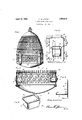
- Figure 1 is a side elevation of a bird cage with the receptacle-attached thereto.
- Figure 2- is an enlarged detail sectional view transversely through the lower portion of the cage and receptacles thereon.
- Figure 3 is an enlarged elevation of the.
- Figure 4 is a sectional view as seen along line M, Fig. 3.
- Figure 5 is a perspective view of the receptacle removed from the cage.
- the numeral 1 designates the body of acage, at theglower end 'of which" is a band '2 preferably in the form of a grille and which is of sufficient height and configuration to practicallyfcon cealfrom view any objects placed in the lower portion of the cage.
- cups 3 are providechsaid cups being of any'su'itable design and size and preferably provided with rolled edges/f, so that a bird may obtain food or drink fromthe cup without danger of injury to the bird.
- the opening 5 is formed ;until it rests on the platform 7, the outer ends of the rolled edges will strike against the solid portion of the plate 6, through which the opening 5 is formed, on an attempt to remove the cup, thus necessitating that the cup be raised until the rolled edges 4 register with the notches 9, before the cup can be removed
- this cup structure and supporting elements therefor may be attached to the ordinary cage in the same manner as herein set forth.
- the platform 7 is preferably hinged to the plate 6 or adjacent portions of a cage and has a spring 74 for swinging the platform upwardly, on the removal of the cup 3, said platform forming a closure for the opening 5 in the absence of the cup to prevent the escape of the bird through said opening.
- a canopy 10 is placed above each cup and a sufficient distance thereabove to permit the bird to introduceits head between the cup and canopy to obtain food or drink.
- the canopy 10 is preferably formed integral with the plate 6, at the upper portion thereof, although it will be understood that it may be made separate and secured thereto in any suitable manner.
- a handle 11 is attachedto each cup, said handle member being substantially in the form of a rosette configuration, the central portion of which is so extended that it may be readily grasped as a handle for transporting the cup or for Q entering the same into or removing it from the cage.
- the band 2 is so arranged that the bottom forming portion 12 of the cage may be hinged thereto, with the top edge of the bottom entering within the ban d when in closed posi tion so that any articles carried by said bottom will be excluded from view, thus removing all unsightly objects common to the ordi-' nary bird cage equipment.
- the cup like receptacles 3 are preferably constructed of metal or other suitable nonbreakable material, consequently said cups will be indestructible from use and when constructed from metal, they may be stamped into shape and produced at a very nominal cost.
- cup like members insertable through said openings to the interior of said cage structure and removed from view, means on the band for supporting said cup like members,
Description
April 12, 1932. E. w. LITTLE RECEPTACLE FOR BIRD CAGES Filed Sept. 22, 1930 Fla .3.
Patented Apr. 12, 1932 UNITED? STA EARL W. LITTLE, OFIN'DIANAPOLIS, INDIANA PATENT! OFFICE RECEPTACLE FOR BIRD CAGES Application filed September 22,1930. 7 Serial No. 483,538.
This invention relates to receptacles for bird cages and the prime feature of the invention is the provision of a cup structure adapted to retain food, water or the like.
p A further feature of the invention is in "so attaching the receptacle that it will be cag provision removal of the receptacle from the cage. I
V A further feature of the invention is the provision of means for preventing waste of the water or food from the receptacle.
Other obj ects and advantages will be hereinafter more fullyset forth and pointed out in the accompanying specification.
In the accompanying drawings which are fromthe cage.
made a part of this application,
Figure 1 is a side elevation of a bird cage with the receptacle-attached thereto.
" Figure 2- is an enlarged detail sectional view transversely through the lower portion of the cage and receptacles thereon.
Figure 3 is an enlarged elevation of the.
receptacle andparts associated therewith.
' Figure 4 is a sectional view as seen along line M, Fig. 3.
Figure 5 is a perspective view of the receptacle removed from the cage.
\ Referring to the drawings, the numeral 1 designates the body of acage, at theglower end 'of which" is a band '2 preferably in the form of a grille and which is of sufficient height and configuration to practicallyfcon cealfrom view any objects placed in the lower portion of the cage. i In order to provide receptacles in whichto place food, water and the like, cups 3 are providechsaid cups being of any'su'itable design and size and preferably provided with rolled edges/f, so that a bird may obtain food or drink fromthe cup without danger of injury to the bird.
Each cupisentered through an opening in the grille 2 and through an opening 5 in a'"'plate 6 on the inner face of the grille or band 2 and rests upon a platform 7 extend ing inwardly from the plate 6, the extreme inner end of the platform 7 having an upwardly extending flange 8 for limiting the inwardmovement of the cup on its being inserted through the opening 5.
' In order to prevent casual removal of the cup structure. 3, the opening 5 is formed ;until it rests on the platform 7, the outer ends of the rolled edges will strike against the solid portion of the plate 6, through which the opening 5 is formed, on an attempt to remove the cup, thus necessitating that the cup be raised until the rolled edges 4 register with the notches 9, before the cup can be removed It will be understood that this cup structure and supporting elements therefor may be attached to the ordinary cage in the same manner as herein set forth.
The platform 7 is preferably hinged to the plate 6 or adjacent portions of a cage and has a spring 74 for swinging the platform upwardly, on the removal of the cup 3, said platform forming a closure for the opening 5 in the absence of the cup to prevent the escape of the bird through said opening.v
In order to prevent the bird having bodily access to the cup 3, whereby the contents of the cup might be wasted by the bird scratch-' ing or bathing therein and prevent ofial and other foreign particles from depositing therein, a canopy 10 is placed above each cup and a sufficient distance thereabove to permit the bird to introduceits head between the cup and canopy to obtain food or drink. The canopy 10 is preferably formed integral with the plate 6, at the upper portion thereof, although it will be understood that it may be made separate and secured thereto in any suitable manner.
In order to provide means for readily removing the cup from or entering the same into the opening in the cage, a handle 11 is attachedto each cup, said handle member being substantially in the form of a rosette configuration, the central portion of which is so extended that it may be readily grasped as a handle for transporting the cup or for Q entering the same into or removing it from the cage.
The band 2 is so arranged that the bottom forming portion 12 of the cage may be hinged thereto, with the top edge of the bottom entering within the ban d when in closed posi tion so that any articles carried by said bottom will be excluded from view, thus removing all unsightly objects common to the ordi-' nary bird cage equipment.
The cup like receptacles 3 are preferably constructed of metal or other suitable nonbreakable material, consequently said cups will be indestructible from use and when constructed from metal, they may be stamped into shape and produced at a very nominal cost.
What I claim is:
1. The combination with a cage structure, and a band connected therewith, said band having openings therethrough, of cup like receptacles insertable through said openings, means for supporting said cup like receptacles within the cage structure, means for preventing casual removal of the cup like structures from the cage structure and handle forming means on said cups for concealing said cup and opening and provide means for the removal of the cups.
2. The combination with a cage structure, and a band havin substantially grille configurations and openings therethrough, of cup like receptacles insertable through said openings, means for supporting said cup like members within the cage structure in a manner to exclude the same from view from the exterior of the cage, and handle forming means on said cup like members.
3. The combination with a cage structure, of a band surrounding said cage structure and having openings therethrough, cup like receptacles insertable through said openings, and a support for each cup like member positioned below the lower edge of said openings and on the inner face of said band, whereby said cup like members must be bodily elevated prior to removing the same from said openings.
4. The combination with a cage structure.
and a grille like band surrounding the same, said band having openings therethrough, of
cup like members insertable through said openings to the interior of said cage structure and removed from view, means on the band for supporting said cup like members,
means for regulating the movement of said-V cups in either direction, and a canopy forming'member extending above said cup like members.
5. The combination with a cage structure, and a band surrounding the same, said band having openings therethrough, of cup like members insertable through said openings to the interior of said cage structure, supports for said cup like members carried by said band, and handle forming members for said cups adapted to conceal the outer ends of said cups and the openings through which the cups are entered.
6. The combination with a cage structure, and a band surrounding the same, said band having openings therethrough, of receptacles insertable into said cage structure through said openings, a support for each of said receptacles, means for limiting the inward movement of said receptacles, means for preventing casual removal of the receptacles from the cage structure, and a canopy forming medium above each of said openings.
7. The combination with a cage structure having openings through the side walls thereof, of receptacles insertable into the interior of said cage structure through said openings, supports for said receptacles on the interior of said cage structure, and canopies on the interior of the cage structure and in fixed relation therewith and adapted to extend over and rest in spaced relation with said receptacles.
8. The combination with a cage structure having openings through the side walls thereof, of receptacles insertable into the in terior of the cage through said openings, supports within the cage structure upon which said receptacles rest, and means for swinging said supports into position to form closures for said openings when the receptacles are removed from said openings.
9. The combination with a cage structure having openings through the side walls thereof, a canopy above each opening and fixed to the interior of the cage structure, and a support below each opening and on the interior of said cage structure, of a cuplike receptacle adapted to be entered through each opening and between the canopy and support connected therewith.
10. The combination with a cage structure having openings through the walls thereof, of cups insertable into the interior of the cage structurethrough said openings, and means on the cups for forming closures for said openings when the cups are within the cage and exclude said cups and openings from view.
11. The combination with a cage structure 7 ing inwardly over said receptacle When'inserted, and a support extending inwardly within said cage from points adjacent the lower edge of said opening to support said receptacle when thus inserted.
In testimony whereof, I have hereto set my hand on this the 11th day of July, 1930.
' EARL W. LITTLE.
Priority Applications (1)
| Application Number | Priority Date | Filing Date | Title |
|---|---|---|---|
| US483538A US1853214A (en) | 1930-09-22 | 1930-09-22 | Receptacle for bird cages |
Applications Claiming Priority (1)
| Application Number | Priority Date | Filing Date | Title |
|---|---|---|---|
| US483538A US1853214A (en) | 1930-09-22 | 1930-09-22 | Receptacle for bird cages |
Publications (1)
| Publication Number | Publication Date |
|---|---|
| US1853214A true US1853214A (en) | 1932-04-12 |
Family
ID=23920466
Family Applications (1)
| Application Number | Title | Priority Date | Filing Date |
|---|---|---|---|
| US483538A Expired - Lifetime US1853214A (en) | 1930-09-22 | 1930-09-22 | Receptacle for bird cages |
Country Status (1)
| Country | Link |
|---|---|
| US (1) | US1853214A (en) |
Cited By (3)
| Publication number | Priority date | Publication date | Assignee | Title |
|---|---|---|---|---|
| US3554165A (en) * | 1968-07-08 | 1971-01-12 | Vernon Carter | Animal feeder |
| US20080295707A1 (en) * | 2007-05-31 | 2008-12-04 | Mark Levie | Stuffing cage |
| USD744702S1 (en) * | 2015-01-09 | 2015-12-01 | Visions USA Inc. | Bird feeder hood |
-
1930
- 1930-09-22 US US483538A patent/US1853214A/en not_active Expired - Lifetime
Cited By (4)
| Publication number | Priority date | Publication date | Assignee | Title |
|---|---|---|---|---|
| US3554165A (en) * | 1968-07-08 | 1971-01-12 | Vernon Carter | Animal feeder |
| US20080295707A1 (en) * | 2007-05-31 | 2008-12-04 | Mark Levie | Stuffing cage |
| US8104399B2 (en) * | 2007-05-31 | 2012-01-31 | Mark Levie | Stuffing cage hinged for ease of access |
| USD744702S1 (en) * | 2015-01-09 | 2015-12-01 | Visions USA Inc. | Bird feeder hood |
Similar Documents
| Publication | Publication Date | Title |
|---|---|---|
| US3752120A (en) | Cat litter box | |
| DE4114250A1 (en) | CONTAINERS FOR THE STORAGE AND DISTRIBUTION OF GOODS | |
| US3310031A (en) | Sanitary cat box | |
| US5927492A (en) | Decorative container for storing plumbing plunger | |
| US5988110A (en) | Pet enclosure with waste tray | |
| US2724123A (en) | Pool for children | |
| US2726012A (en) | Flavor-protecting coffee cover | |
| US4007711A (en) | Anti-pest pet dish | |
| US2818681A (en) | Container for plants | |
| US3074583A (en) | Garbage receptacle | |
| US1853214A (en) | Receptacle for bird cages | |
| US3498576A (en) | Post top closure bracket or cap | |
| US769874A (en) | Bait-bucket. | |
| US2610443A (en) | Ground vase | |
| US6331147B1 (en) | Sandbox with attachable cover | |
| US3724745A (en) | Combination of bar stool and refuse container | |
| US1732988A (en) | Incinerator | |
| US2002259A (en) | Animal den | |
| US2100909A (en) | Automatic roach trap | |
| US3191190A (en) | Portable collapsible health bath | |
| US1686048A (en) | Grave cover | |
| US1899400A (en) | Easy lift sanitary flower container | |
| US3075692A (en) | Wall hung trash receptacle | |
| US1807271A (en) | Attachment for frying pans | |
| US112748A (en) | Improvement in floral-brackets |