US1853213A - Quickly attachable and detachable rotor brake and contact wiper - Google Patents
Quickly attachable and detachable rotor brake and contact wiper Download PDFInfo
- Publication number
- US1853213A US1853213A US470094A US47009430A US1853213A US 1853213 A US1853213 A US 1853213A US 470094 A US470094 A US 470094A US 47009430 A US47009430 A US 47009430A US 1853213 A US1853213 A US 1853213A
- Authority
- US
- United States
- Prior art keywords
- rotor
- shaft
- frame
- plates
- contact
- Prior art date
- Legal status (The legal status is an assumption and is not a legal conclusion. Google has not performed a legal analysis and makes no representation as to the accuracy of the status listed.)
- Expired - Lifetime
Links
Images
Classifications
-
- H—ELECTRICITY
- H01—ELECTRIC ELEMENTS
- H01G—CAPACITORS; CAPACITORS, RECTIFIERS, DETECTORS, SWITCHING DEVICES, LIGHT-SENSITIVE OR TEMPERATURE-SENSITIVE DEVICES OF THE ELECTROLYTIC TYPE
- H01G5/00—Capacitors in which the capacitance is varied by mechanical means, e.g. by turning a shaft; Processes of their manufacture
- H01G5/38—Multiple capacitors, e.g. ganged
Definitions
- My present invention is directed to an improved method of obtaining this braking ac tion and also at the same time to insure that good electrical contact may he secured with the rotor,
- the use of ball bearings naturally reduces the friction between the shaft and its mounting supports, and consequently reduces the electrical contwt het-weenfthe 45 plied or removed for the purpose of? changing"v the tension of the braking device, or even using one of difierent grade of material, whereby in a gang condenser, same may he quickly adiusted with respect to the to braking action improvement v be LE AND DETAQMABLE 3o rotor plates and the frame of the condenser .vided with a hall hearingh, and
- l is a plan view of a four-gang condenser
- Figure A Figure 3 is an end viewoi the he and contact wiper, looking from the right of Figure 2.
- 1 is the framework oil a condenser having hearing plates 2 and 3 carrying a rotor shaft 4; The plate is pron said with a hall hearing 6, all as set to- Cranier patent,
- the to sleeve '3' carries rotor plates 9, least one end of which are held together by a tie 10.
- the stator plates 11 are fastened by tie bars 12, which are supported by insulators 13, one end of which is attached to the frame 1.
- A is struck inwardly fro plate 2 acts as a stop for the pi ened to shaft l, thereby lin movement of the rotor shaft in capacity position
- Each of the units of the condenser is separated by a co hi shield brace plate 16, which i extend oeyond the edges oi the therin desired, complete a he fitted around the entire u but since this forms no of invention h We not shown it in ings.
- each of the condenser may he provided wi trimming cond as sho n and described in my an Serial Number 469,033, filed July
- Each o the plates 16, is provided orifice positioned in this n we is 9.
- each wiper member 19 which is adjacent the projection 18, is provided with a lug 24 preferably bent away from the end plate or brace plate which is thus a. part of the condenser frame and on which it is mounted.
- Each .lug 24 has a hole 25 therein, to which the ground wire may be attached, as by soldering, thereby insuring a good contact with the rotor.
- the shield and brace plate 16' acts to prevent electrostatic coupling of the units of the gang condenser
- the plates 16 are usually thick enough so that one orifice 17 is suflicient to accommodate the projections 18 on the'two members 19 carried on opposite sides of the plates 16.
- the position of one of the members 19, comprising a pair engaging any one of the plates 16, may be reversed in position by providing another ori-' fice 17 on the opposite side of the shaft 4.
- the combined brake and contact wiper 19 may be quickly attached or detached from the condenser. and if the form given to the members 19 by the tools in the manufacture is 'not'just exactly correct to get the proper result, the members 19 may be quickly bent and the device slipped into place where it is held by Having thus described my invention, what I claim is:
- a combined brake and contact wiper for said shaft and rotor consisting of a forked and curved resilient member having its opposite ends engaging a part of the frame, one end having a quick detachable anchorage on a part of the frame, while the other end is free to slide on the frame, the forked parts of said member straddling the shaft and having outwardly forced portions to engage a part of the rotor, and means for making a circuit connection to said member.
- a combined brake and contact wiper for said shaft and rotor consisting of a curved resilient member having a projection near one end to seat in an openin in a part of the frame,-said member being orked and the forked ends straddling the shaftand engaging the frame, said forkedends having outwardly formed contacts adjacent the shaft to engage a part of the rotor, and means ior making a circuit connection to said mem- 3.
- a gang condenser having a frame including frame members such as end, shield and brace plates, a shaft and unit condensers positioned between pairs of said plates, each of said unit condensers comprising a stator carried on the frame and a rotor consisting of a sleeve and plates attached thereto carried by the shaft; a quickly attachable and detachable rotor brake and contact wiper consisting of, a forked and curved spring member positioned between one of said frame plates and the end of a rotor sleeve, said spring member being held in position by projecting and seat means cooperating between the spring member and its frame plate, the forked end passing around the shaft and engaging the end of the rotor, means on said forked ends to insure a good contact on the rotor sleeve. and means .on said spring member for making a circuit connection therewith.
- a gang condenser having a frame including frame members suchas end, shield and brace plates, a shaft and unit condensers positioned between pairs of said plates, each' of said unit condensers comprising a stator carried on the frame and a rotor consisting of a sleeve and plates attached thereto carried by the shaft; a quickly attachable and detachable rotor brake and contact wiper for each condenser consisting of, a forked bow spring engaging at its ends a frame member and'tensioned between said member and the end of a rotor sleeve cooperating means between the spring and its frame member to slidably holdthe spring in place, the forked end of the spring straddling the shaft and engaging the end of the rotor, means on said forked ends to insure a good contact on the rotor sleeve, and means on said spring memberhfor making a circuit connection therewit 5.
- variable gang condenser including a frame and shaft and a plurality of rotors carried by the shaft, conjoint means for reducing'stray coupling between the unit condensers of the gang and obtaining a braking action for the rotor systems, said 'conjoint means comprising a plurality, at
Landscapes
- Engineering & Computer Science (AREA)
- Power Engineering (AREA)
- Microelectronics & Electronic Packaging (AREA)
- Braking Arrangements (AREA)
Description
April 12, 1932. KQEPPING 1,853,213
QUICKLY ATTACHABLE AND DETACHABLE ROTOR BRAKE AND CONTACT WIFER Fil ed July 23, 1930 EM/L D. KOEPP/NG January 15, 1929, by Stanley S. Granier, now a Patented Apr. 12, 1932 UNITED I ST EHIL D. KOEPPING, 0F HADEQTQ HEIGHTS,
.ellbW ASSKGNGE ii'Q $6115 DENSER UQMTPAN'Y, fill? CAMDEEE', an JERSEY."
\ QUIGKLY ATTAC I Application filed duly Patent 1,800,719, issued April 1t,'1931, there is shown and described an improved "form of condenser in which the'rotor or rotors are carried on a shaft supported on antifrictional 1n bearings, the idea being to eliminate to the greatestextent, the difiiculties caused by misalignment in the manufacturing processes or" the shaft, and distortion of the rotor plates due to binding of the shaft, and. other trou- 15 bles encountered in manufacture. In the said Cramer patent, special means are shown and described for applying a definite amount ofloraking action or friction to the shaft as desired, in order to hold the rotor or rotors so in any position to which they may he turned by the operator.
My present invention is directed to an improved method of obtaining this braking ac tion and also at the same time to insure that good electrical contact may he secured with the rotor, The use of ball bearings naturally reduces the friction between the shaft and its mounting supports, and consequently reduces the electrical contwt het-weenfthe 45 plied or removed for the purpose of? changing"v the tension of the braking device, or even using one of difierent grade of material, whereby in a gang condenser, same may he quickly adiusted with respect to the to braking action improvement v be LE AND DETAQMABLE 3o rotor plates and the frame of the condenser .vided with a hall hearingh, and
understood by reference to the annexed drawin "s, z"
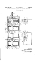
l is a plan view of a four-gang condenser,
l igure 2 is a section on the line 22 I?! Figure A Figure 3 is an end viewoi the he and contact wiper, looking from the right of Figure 2.
Referring now to the details, wh in like nunihers refer to corresponding par Us in the various views, 1 is the framework oil a condenser having hearing plates 2 and 3 carrying a rotor shaft 4; The plate is pron said with a hall hearing 6, all as set to- Cranier patent,
Carried on the shaft 4, is pl of sleeves 7 fastened to the shaft l any satisi actor manner as byset screws The to sleeve '3' carries rotor plates 9, least one end of which are held together by a tie 10. The stator plates 11 are fastened by tie bars 12, which are supported by insulators 13, one end of which is attached to the frame 1.
A is struck inwardly fro plate 2 acts as a stop for the pi ened to shaft l, thereby lin movement of the rotor shaft in capacity position Each of the units of the condenser is separated by a co hi shield brace plate 16, which i extend oeyond the edges oi the therin desired, complete a he fitted around the entire u but since this forms no of invention h We not shown it in ings. Also, each of the condenser may he provided wi trimming cond as sho n and described in my an Serial Number 469,033, filed July Each o the plates 16, is provided orifice positioned in this n we is 9.
l8 formed in the brake and con member 19. This latter nieinher -en in a curvilinear manner as shownno 'i, and has two forks 2'0 21 which straddle the The ee of the forks 20 and 21 are preferably curved at 22 where they engage the plate 16.
In order to insure that the forks 20 and 21 make a good contact with the rotor sleeve 7 they are each provided with outwardly forced ribs, edges or projections 23 which bear directly against the end of the rotor sleeve 7, so that as the shaft 1- is turned and likewise the sleeve 7, these ribs 23 make a good wiping, self-cleaning contact directly on the sleeves which are preferably made of good conducting material. The end of each wiper member 19, which is adjacent the projection 18, is provided with a lug 24 preferably bent away from the end plate or brace plate which is thus a. part of the condenser frame and on which it is mounted. Each .lug 24 has a hole 25 therein, to which the ground wire may be attached, as by soldering, thereby insuring a good contact with the rotor.
In some cases it may be found desirable to use the combined brake and contact wiper member 19 at each end of the rotor sleeves 7 as shown in Figure 1, whereby a yielding braking effort is applied to both ends of the metallic sleeve carrying the rotor plates. The use of the members 19 against each end of the rotor sleeves, insures a good electrical con tact with the rotor, as this yielding connection provides an automatic self-scouring contact, which is highly essential in a receiving set which is some times permitted to remain unoperated for a considerable period a of time, the effect of which. is that the metal oxidizes and acts to produce abad contact. The construction herein disclosed will immediately, on turning of the :rotor' shaft, scour off any oxide which may haveaccumulated on the end of the rotor sleeve or even on the contact wiper itself, and will thus secure a definite circuit connection for the rotor or rotors.
- While the shield and brace plate 16' acts to prevent electrostatic coupling of the units of the gang condenser, the members 19, by reason of securing good electrical contact with the rotors, act to equalize the potential of the rotors or bring them to the same electrical level and thereby prevent stray coupling due to varying potentials between the rotors of the different units.
In practice the plates 16 are usually thick enough so that one orifice 17 is suflicient to accommodate the projections 18 on the'two members 19 carried on opposite sides of the plates 16. However, if desired the position of one of the members 19, comprising a pair engaging any one of the plates 16, may be reversed in position by providing another ori-' fice 17 on the opposite side of the shaft 4.
As will be seen from Figure 1, the combined brake and contact wiper 19 may be quickly attached or detached from the condenser. and if the form given to the members 19 by the tools in the manufacture is 'not'just exactly correct to get the proper result, the members 19 may be quickly bent and the device slipped into place where it is held by Having thus described my invention, what I claim is: I
1. For an electrical condenser having a frame and shaft and a rotor carried by the shaft, a combined brake and contact wiper for said shaft and rotor, consisting of a forked and curved resilient member having its opposite ends engaging a part of the frame, one end having a quick detachable anchorage on a part of the frame, while the other end is free to slide on the frame, the forked parts of said member straddling the shaft and having outwardly forced portions to engage a part of the rotor, and means for making a circuit connection to said member.
2. For an electrical condenser having a frame and shaft and a rotor carried by-the shaft, a combined brake and contact wiper for said shaft and rotor, consisting of a curved resilient member having a projection near one end to seat in an openin in a part of the frame,-said member being orked and the forked ends straddling the shaftand engaging the frame, said forkedends having outwardly formed contacts adjacent the shaft to engage a part of the rotor, and means ior making a circuit connection to said mem- 3. For a gang condenser having a frame including frame members such as end, shield and brace plates, a shaft and unit condensers positioned between pairs of said plates, each of said unit condensers comprising a stator carried on the frame and a rotor consisting of a sleeve and plates attached thereto carried by the shaft; a quickly attachable and detachable rotor brake and contact wiper consisting of, a forked and curved spring member positioned between one of said frame plates and the end of a rotor sleeve, said spring member being held in position by projecting and seat means cooperating between the spring member and its frame plate, the forked end passing around the shaft and engaging the end of the rotor, means on said forked ends to insure a good contact on the rotor sleeve. and means .on said spring member for making a circuit connection therewith.
4. For a gang condenser having a frame including frame members suchas end, shield and brace plates, a shaft and unit condensers positioned between pairs of said plates, each' of said unit condensers comprising a stator carried on the frame and a rotor consisting of a sleeve and plates attached thereto carried by the shaft; a quickly attachable and detachable rotor brake and contact wiper for each condenser consisting of, a forked bow spring engaging at its ends a frame member and'tensioned between said member and the end of a rotor sleeve cooperating means between the spring and its frame member to slidably holdthe spring in place, the forked end of the spring straddling the shaft and engaging the end of the rotor, means on said forked ends to insure a good contact on the rotor sleeve, and means on said spring memberhfor making a circuit connection therewit 5. For a variable gang condenser including a frame and shaft and a plurality of rotors carried by the shaft, conjoint means for reducing'stray coupling between the unit condensers of the gang and obtaining a braking action for the rotor systems, said 'conjoint means comprising a plurality, at
least one for each rotor of the gang, of forked resilient members, each having a quick detachable anchorage atone end on a part of the frame and slidably engaging the frame at the forked ends, said forked ends straddling the shaft and having projection portions in scouring engagement with a part of its associated rotor. v
In testimony whereof, I affix my signature.
- EMIL D. KOEPPING.
Priority Applications (1)
| Application Number | Priority Date | Filing Date | Title |
|---|---|---|---|
| US470094A US1853213A (en) | 1930-07-23 | 1930-07-23 | Quickly attachable and detachable rotor brake and contact wiper |
Applications Claiming Priority (1)
| Application Number | Priority Date | Filing Date | Title |
|---|---|---|---|
| US470094A US1853213A (en) | 1930-07-23 | 1930-07-23 | Quickly attachable and detachable rotor brake and contact wiper |
Publications (1)
| Publication Number | Publication Date |
|---|---|
| US1853213A true US1853213A (en) | 1932-04-12 |
Family
ID=23866241
Family Applications (1)
| Application Number | Title | Priority Date | Filing Date |
|---|---|---|---|
| US470094A Expired - Lifetime US1853213A (en) | 1930-07-23 | 1930-07-23 | Quickly attachable and detachable rotor brake and contact wiper |
Country Status (1)
| Country | Link |
|---|---|
| US (1) | US1853213A (en) |
Cited By (1)
| Publication number | Priority date | Publication date | Assignee | Title |
|---|---|---|---|---|
| US3341756A (en) * | 1966-06-16 | 1967-09-12 | John E Johanson | Adjustable low-pass capacitor |
-
1930
- 1930-07-23 US US470094A patent/US1853213A/en not_active Expired - Lifetime
Cited By (1)
| Publication number | Priority date | Publication date | Assignee | Title |
|---|---|---|---|---|
| US3341756A (en) * | 1966-06-16 | 1967-09-12 | John E Johanson | Adjustable low-pass capacitor |
Similar Documents
| Publication | Publication Date | Title |
|---|---|---|
| US1853213A (en) | Quickly attachable and detachable rotor brake and contact wiper | |
| DE102011121062A1 (en) | Drive device, in particular for an electronic household appliance | |
| US2314855A (en) | Electrical terminal and terminal installation | |
| US1716144A (en) | Terminal device | |
| DE1057241B (en) | Rectifier arrangement with semiconductor element | |
| DE112012002900T5 (en) | Quickly mounted capacitor | |
| US1537692A (en) | Disk commutator | |
| DE717609C (en) | Fastening the brush holder in electrical machines | |
| DE711924C (en) | Contact spring | |
| DE605322C (en) | Interference protection on electrical machines in the form of a capacitor connected between the collector brushes and the machine housing | |
| DE69302356T2 (en) | Electrodynamic machine with ironing brushes | |
| US2019177A (en) | Electric switch | |
| DE4321475A1 (en) | Commutation brush | |
| US1808549A (en) | Brush for dynamo-electric machines | |
| US1665550A (en) | Contact holder | |
| DE4440942A1 (en) | Electrical connector and brush-holder for rotary electrical machine | |
| US2404246A (en) | Brush rigging | |
| DE112015006979B4 (en) | Semiconductor device | |
| US2438510A (en) | Electrical contact brush | |
| AT153775B (en) | Plug-in switch. | |
| US960095A (en) | Brush-holder for dynamo-electric machines. | |
| DE707737C (en) | Interference protection for electrical machines | |
| DE102014207002A1 (en) | Electric motor with a commutator device | |
| AT265402B (en) | Installation circuit breaker with a fastening device for a neutral conductor rail | |
| DE1076209B (en) | Insulation sheet printed with conductor tracks and fitted with electrical components |