US1853112A - Tank - Google Patents
Tank Download PDFInfo
- Publication number
- US1853112A US1853112A US363513A US36351329A US1853112A US 1853112 A US1853112 A US 1853112A US 363513 A US363513 A US 363513A US 36351329 A US36351329 A US 36351329A US 1853112 A US1853112 A US 1853112A
- Authority
- US
- United States
- Prior art keywords
- shell
- head
- tank
- lining
- metal
- Prior art date
- Legal status (The legal status is an assumption and is not a legal conclusion. Google has not performed a legal analysis and makes no representation as to the accuracy of the status listed.)
- Expired - Lifetime
Links
- 239000002184 metal Substances 0.000 description 20
- 229910052751 metal Inorganic materials 0.000 description 20
- 239000000126 substance Substances 0.000 description 9
- 229910000831 Steel Inorganic materials 0.000 description 3
- 238000010438 heat treatment Methods 0.000 description 3
- 229910000679 solder Inorganic materials 0.000 description 3
- 239000010959 steel Substances 0.000 description 3
- 238000005219 brazing Methods 0.000 description 2
- 239000007788 liquid Substances 0.000 description 2
- 239000000463 material Substances 0.000 description 2
- 230000002093 peripheral effect Effects 0.000 description 2
- XLYOFNOQVPJJNP-UHFFFAOYSA-N water Substances O XLYOFNOQVPJJNP-UHFFFAOYSA-N 0.000 description 2
- 229910001369 Brass Inorganic materials 0.000 description 1
- RYGMFSIKBFXOCR-UHFFFAOYSA-N Copper Chemical compound [Cu] RYGMFSIKBFXOCR-UHFFFAOYSA-N 0.000 description 1
- 241000557626 Corvus corax Species 0.000 description 1
- 229910000792 Monel Inorganic materials 0.000 description 1
- 239000010951 brass Substances 0.000 description 1
- 229910052802 copper Inorganic materials 0.000 description 1
- 239000010949 copper Substances 0.000 description 1
- 108010085990 projectin Proteins 0.000 description 1
- 230000000630 rising effect Effects 0.000 description 1
- 238000003466 welding Methods 0.000 description 1
Images
Classifications
-
- A—HUMAN NECESSITIES
- A61—MEDICAL OR VETERINARY SCIENCE; HYGIENE
- A61F—FILTERS IMPLANTABLE INTO BLOOD VESSELS; PROSTHESES; DEVICES PROVIDING PATENCY TO, OR PREVENTING COLLAPSING OF, TUBULAR STRUCTURES OF THE BODY, e.g. STENTS; ORTHOPAEDIC, NURSING OR CONTRACEPTIVE DEVICES; FOMENTATION; TREATMENT OR PROTECTION OF EYES OR EARS; BANDAGES, DRESSINGS OR ABSORBENT PADS; FIRST-AID KITS
- A61F7/00—Heating or cooling appliances for medical or therapeutic treatment of the human body
-
- B—PERFORMING OPERATIONS; TRANSPORTING
- B65—CONVEYING; PACKING; STORING; HANDLING THIN OR FILAMENTARY MATERIAL
- B65D—CONTAINERS FOR STORAGE OR TRANSPORT OF ARTICLES OR MATERIALS, e.g. BAGS, BARRELS, BOTTLES, BOXES, CANS, CARTONS, CRATES, DRUMS, JARS, TANKS, HOPPERS, FORWARDING CONTAINERS; ACCESSORIES, CLOSURES, OR FITTINGS THEREFOR; PACKAGING ELEMENTS; PACKAGES
- B65D90/00—Component parts, details or accessories for large containers
- B65D90/02—Wall construction
- B65D90/08—Interconnections of wall parts; Sealing means therefor
-
- Y—GENERAL TAGGING OF NEW TECHNOLOGICAL DEVELOPMENTS; GENERAL TAGGING OF CROSS-SECTIONAL TECHNOLOGIES SPANNING OVER SEVERAL SECTIONS OF THE IPC; TECHNICAL SUBJECTS COVERED BY FORMER USPC CROSS-REFERENCE ART COLLECTIONS [XRACs] AND DIGESTS
- Y10—TECHNICAL SUBJECTS COVERED BY FORMER USPC
- Y10S—TECHNICAL SUBJECTS COVERED BY FORMER USPC CROSS-REFERENCE ART COLLECTIONS [XRACs] AND DIGESTS
- Y10S220/00—Receptacles
- Y10S220/917—Corrosion resistant container
Definitions
- the invention relates to an improvement in tanks. It is especially intended for application to tanks which are intended for use as containers for hot water or other liquids or substances which have a tendency to corrode metal.
- the tank is made entirely of sheet steel or other corrodible metal, it soon becomes corroded thereby causing the tank to leak and discoloring the liquid in the tank.
- the use of non-corrodible metal for the entire tank is very expensive if the sheets of which the tank is made are sufiiciently thick to give the necessary strength. It has, therefore, become common to make the tank with an inner shell or lining of non-corrodible metal and with an outer or reenforcing'shell of steel or other relatively cheap metal which is corrodible.
- One object of the present invention is to provide a joint between the heads and the ends of the shell which will be non-corrodible.
- Another object is to provide an interlocking joint between the heads and the ends of' shell of the tank both to prevent leakage and to resist the outward pressure of the contents of the tank.
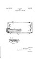
- Fig. 1 is a longitudinal section of a tank embodying the invention.
- Fig. 2 is an enlarged detail vieiw showing. the joint between one of the heads and the inner shell of non-corrodible sheet metal;-
- each of these shells may be made of'sheet metal rolled into cylindrical form and having a longitudinal union or joint at the meeting edges.
- the ends of the tank are provided respectively with two heads, B, C preferably dished inward.
- a heating element connected with the head C in any suitable manner. Any suitable heating element may be used for this purpose or the heating element may be omitted, the invention not being limited to use with hot water tanks.
- the head B is formed with an outer plate 12 which may be of corrodible metal and a thin lining member 13 of non-corrodible sheet metal similar to the outer and inner members ofthe cylindrical portion of the tank.
- the head C is formed with an outer kind of metal, and an inner lining 15 of noncorrodible metal.
- the reenforcing head member 12 has a peripheral flange 21 which extends outwardly parallel'with the outer shell portion 10 and the non-corrodible lining member 13 has a flange which extends parallel with and in I 11 and 13.
- the outer shell 10 is preferably formed on its inner periphery with a peripheral notch or groove 22;
- the reenforcing outer shell 10, the reenforcing disk 21 of the head, and the twointerposed noncorrodible lining members 11 and 13 are all secured together by a filling of solder, welding material or brazing 23 or equivalent material as shown in Fig. 2.
- This solder or brazing substance will completely close the joint at the end between the two lining members of the head and the outer shell and prevent moisture from passing through the joint.
- the interlocking of the solder 23 with the notch in the outer shell 10 performs a.further function in that it resists the outward pressure of the contents of the tank against the head.
- the interlocking connection of the head C with the tank is similar to that of the head B. 100
- a sheet metal tank comprising an inner tubular shell of non-corrodible sheet metal, a reenforcing outer metal shell, said tank having a metallic head comprising an outer disk of metal and a lining of non-corrodible metal, said head being inserted into the end of the shell, each member of said head having an annular flange, the flange of the noncorrodible head lining fitting against the inn'er'periphery of the lining of the tubular shell, a" binding substance uniting the said head to the tubular shell at its ends'and covering the joint between the head and the shell, the outer shell extending some distance beyond the end of the head flange, the outer shell being formed with a notch into which the said binding substance extends.
- a tank comprising an outer metallic tubular shell, a lining shell therefor of noncorrodible metal, a metallic head fitted into said shell at some distance back from the end ofthe shell and having a cylindrical petending outward somewhat beyond the ends of the said tubular linings of the shell and of the head members, the projectin portion of said outer shell having an annu ar notch in its inner peripher and a binding substance which covers t e ends of said lining shell and of said head flanges and' engages r with said notch.
- the linings of the shell I and the head member pro'ecting upwardbeyond the tubular flange o the main head member, the projecting portion of said outer shell having an annular notch in its inner periphery and a binding substance Which' covers the ends of said lining shell and of said head flanges and engages with said notch.
- ripheral flange extending toward the end of a the shell, the outer shell extendingbeyond the end of the said head flange, said extension having an annular hotch in its inner periphery, and a binding substance 'filling said notch and the flanges.
- a tank consisting of a tubular metallic shell formed with a recess inits inner periphery near the end of the shell, .a metallic head inserted into said shell somewhat further in from the end than the said recess, said head having an annular flange extending toward the outer end of the shell and lying against the inner face of the shell, and a uniting substance covering the joint between the inner and extending into said recess.
- a tank comprising an outer metallic tubular shell, a metallic lining shell therefor, a metallic head comprising an outer disk covering the joints between and a metalliclining therefor, said head and its lining each having a cylindrical flange.
Landscapes
- Health & Medical Sciences (AREA)
- Engineering & Computer Science (AREA)
- Biomedical Technology (AREA)
- Heart & Thoracic Surgery (AREA)
- Vascular Medicine (AREA)
- Life Sciences & Earth Sciences (AREA)
- Animal Behavior & Ethology (AREA)
- General Health & Medical Sciences (AREA)
- Public Health (AREA)
- Veterinary Medicine (AREA)
- Mechanical Engineering (AREA)
- Filling Or Discharging Of Gas Storage Vessels (AREA)
Description
April 12, 1932. F. 5 BQLTZ 1,853,112
TANK
Origina.l Filed Jan. 20, 1928 $24 62 M By WLW,G-6M.W Fad- 14. I
[raven tor.-
Patented' Apr. 12, 1932 UNITED STATES- FRED S. BOIITZ, OI MANSFIELD, MASSACHUSETTS TANK Original application nled January 20, 1928, Serial No. 248,146. Divided and this application filed May 16,
' 1929. Serial No. 363,513.
The invention relates to an improvement in tanks. It is especially intended for application to tanks which are intended for use as containers for hot water or other liquids or substances which have a tendency to corrode metal. When the tank is made entirely of sheet steel or other corrodible metal, it soon becomes corroded thereby causing the tank to leak and discoloring the liquid in the tank. The use of non-corrodible metal for the entire tank is very expensive if the sheets of which the tank is made are sufiiciently thick to give the necessary strength. It has, therefore, become common to make the tank with an inner shell or lining of non-corrodible metal and with an outer or reenforcing'shell of steel or other relatively cheap metal which is corrodible.
This application is a division of an application filed by me January 20, 1928, Serial No. 248,146 and relates to the connection between the heads and the "body of the tank.
One object of the present invention is to provide a joint between the heads and the ends of the shell which will be non-corrodible.
Another object is to provide an interlocking joint between the heads and the ends of' shell of the tank both to prevent leakage and to resist the outward pressure of the contents of the tank.
The invention will be fully understood from the following description when taken in connection with the accompanying drawings and the novel features thereof will be pointed out and clearlydefined in the claims at the close of this specification.
Fig. 1 is a longitudinal section of a tank embodying the invention.
Fig. 2 is an enlarged detail vieiw showing. the joint between one of the heads and the inner shell of non-corrodible sheet metal;-
' preferably brass, copper or monel. Each of these shells may be made of'sheet metal rolled into cylindrical form and having a longitudinal union or joint at the meeting edges.
The reenforcing head member 12 has a peripheral flange 21 which extends outwardly parallel'with the outer shell portion 10 and the non-corrodible lining member 13 has a flange which extends parallel with and in I 11 and 13. The outer shell 10 is preferably formed on its inner periphery with a peripheral notch or groove 22; The reenforcing outer shell 10, the reenforcing disk 21 of the head, and the twointerposed noncorrodible lining members 11 and 13 are all secured together by a filling of solder, welding material or brazing 23 or equivalent material as shown in Fig. 2. This solder or brazing substance will completely close the joint at the end between the two lining members of the head and the outer shell and prevent moisture from passing through the joint. The interlocking of the solder 23 with the notch in the outer shell 10 performs a.further function in that it resists the outward pressure of the contents of the tank against the head.
The interlocking connection of the head C with the tank is similar to that of the head B. 100
' and outer members of thefhead and the shell What I claim is:
1. A metal tank com rising a tubular outer shell, a lining there or of non-corrodible metal, the outer shell extending beyond the end of the lining shell, a metallic head comprising an outer disk and a non-corrodible metal lining therefor fitted into the end of the shell, said head and lining disks each having a cylindrical flange which extends toward the outer end of the shell, the outer shell extending somewhat beyond the end of the lining shell and the head flanges, the extended portion of said outer shell having an annular notch in its inner periphery, anda binding substance filling said notch and covering the ends of said lining shell and the ends of the head flanges.
' 2. A sheet metal tank comprising an inner tubular shell of non-corrodible sheet metal, a reenforcing outer metal shell, said tank having a metallic head comprising an outer disk of metal and a lining of non-corrodible metal, said head being inserted into the end of the shell, each member of said head having an annular flange, the flange of the noncorrodible head lining fitting against the inn'er'periphery of the lining of the tubular shell, a" binding substance uniting the said head to the tubular shell at its ends'and covering the joint between the head and the shell, the outer shell extending some distance beyond the end of the head flange, the outer shell being formed with a notch into which the said binding substance extends.
3. A tank comprising an outer metallic tubular shell, a lining shell therefor of noncorrodible metal, a metallic head fitted into said shell at some distance back from the end ofthe shell and having a cylindrical petending outward somewhat beyond the ends of the said tubular linings of the shell and of the head members, the projectin portion of said outer shell having an annu ar notch in its inner peripher and a binding substance which covers t e ends of said lining shell and of said head flanges and' engages r with said notch.
of the head members, the linings of the shell I and the head member pro'ecting upwardbeyond the tubular flange o the main head member, the projecting portion of said outer shell having an annular notch in its inner periphery and a binding substance Which' covers the ends of said lining shell and of said head flanges and engages with said notch.
In testimony whereof I aflix my signature.
FRED S. BOLTZ.
ripheral flange extending toward the end of a the shell, the outer shell extendingbeyond the end of the said head flange, said extension having an annular hotch in its inner periphery, and a binding substance 'filling said notch and the flanges.
4. A tank consisting of a tubular metallic shell formed with a recess inits inner periphery near the end of the shell, .a metallic head inserted into said shell somewhat further in from the end than the said recess, said head having an annular flange extending toward the outer end of the shell and lying against the inner face of the shell, and a uniting substance covering the joint between the inner and extending into said recess. I
5. A tank comprising an outer metallic tubular shell, a metallic lining shell therefor, a metallic head comprising an outer disk covering the joints between and a metalliclining therefor, said head and its lining each having a cylindrical flange.
which extends axially outward, the said linmg flange of the head fitting into the mouth of:
the shell lining, the oute'rt'ubular shell exi
Priority Applications (1)
| Application Number | Priority Date | Filing Date | Title |
|---|---|---|---|
| US363513A US1853112A (en) | 1928-01-20 | 1929-05-16 | Tank |
Applications Claiming Priority (2)
| Application Number | Priority Date | Filing Date | Title |
|---|---|---|---|
| US248146A US1797257A (en) | 1928-01-20 | 1928-01-20 | Tank |
| US363513A US1853112A (en) | 1928-01-20 | 1929-05-16 | Tank |
Publications (1)
| Publication Number | Publication Date |
|---|---|
| US1853112A true US1853112A (en) | 1932-04-12 |
Family
ID=26939127
Family Applications (1)
| Application Number | Title | Priority Date | Filing Date |
|---|---|---|---|
| US363513A Expired - Lifetime US1853112A (en) | 1928-01-20 | 1929-05-16 | Tank |
Country Status (1)
| Country | Link |
|---|---|
| US (1) | US1853112A (en) |
Cited By (3)
| Publication number | Priority date | Publication date | Assignee | Title |
|---|---|---|---|---|
| US2993617A (en) * | 1959-06-01 | 1961-07-25 | Rheem Mfg Co | Lined tank and method of making |
| US3458224A (en) * | 1968-01-10 | 1969-07-29 | Cessna Aircraft Co | Weld joint |
| US4320847A (en) * | 1979-07-31 | 1982-03-23 | Gernot Gesser | Container for receiving and storing spent fuel elements |
-
1929
- 1929-05-16 US US363513A patent/US1853112A/en not_active Expired - Lifetime
Cited By (3)
| Publication number | Priority date | Publication date | Assignee | Title |
|---|---|---|---|---|
| US2993617A (en) * | 1959-06-01 | 1961-07-25 | Rheem Mfg Co | Lined tank and method of making |
| US3458224A (en) * | 1968-01-10 | 1969-07-29 | Cessna Aircraft Co | Weld joint |
| US4320847A (en) * | 1979-07-31 | 1982-03-23 | Gernot Gesser | Container for receiving and storing spent fuel elements |
Similar Documents
| Publication | Publication Date | Title |
|---|---|---|
| US2209290A (en) | Noncorrosive vessel | |
| US1771765A (en) | Waterproof paper receptacle | |
| US2263021A (en) | Domestic hot water tank | |
| US1748138A (en) | Container for liquids or gases under pressure and method of making the same | |
| US2356047A (en) | Container | |
| US2136474A (en) | Alloy lining for tubular parts | |
| US1853112A (en) | Tank | |
| US1883086A (en) | Flexible pipe and coupling | |
| US2361636A (en) | Connection for hot-water tanks | |
| US2374733A (en) | Connection for lined tanks | |
| US1343169A (en) | Tank | |
| US2127269A (en) | Range boiler | |
| US2353477A (en) | Hot-water tank connection | |
| US2354532A (en) | Hot water tank construction | |
| US2283066A (en) | Closed receptacle | |
| US2039255A (en) | Fluid container and method of welding the same | |
| US1797257A (en) | Tank | |
| US2232366A (en) | Range boiler or storage tank for domestic hot water and domestic hot water heaters | |
| US2403670A (en) | Corrosion-resistant fluid heating tank | |
| US2553342A (en) | Nonturnable spud | |
| US1815543A (en) | Tank | |
| US3319980A (en) | Dip tube connection | |
| US2071602A (en) | Noncorrosive lined container | |
| US2290515A (en) | Welding end plug for piping | |
| US3058624A (en) | Plural walled container |