US1853110A - Lock for tilting drum concrete mixers - Google Patents
Lock for tilting drum concrete mixers Download PDFInfo
- Publication number
- US1853110A US1853110A US325347A US32534728A US1853110A US 1853110 A US1853110 A US 1853110A US 325347 A US325347 A US 325347A US 32534728 A US32534728 A US 32534728A US 1853110 A US1853110 A US 1853110A
- Authority
- US
- United States
- Prior art keywords
- tilting
- drum
- pinion
- gear
- lock
- Prior art date
- Legal status (The legal status is an assumption and is not a legal conclusion. Google has not performed a legal analysis and makes no representation as to the accuracy of the status listed.)
- Expired - Lifetime
Links
- 238000010276 construction Methods 0.000 description 3
- 235000015250 liver sausages Nutrition 0.000 description 1
- XYSQXZCMOLNHOI-UHFFFAOYSA-N s-[2-[[4-(acetylsulfamoyl)phenyl]carbamoyl]phenyl] 5-pyridin-1-ium-1-ylpentanethioate;bromide Chemical compound [Br-].C1=CC(S(=O)(=O)NC(=O)C)=CC=C1NC(=O)C1=CC=CC=C1SC(=O)CCCC[N+]1=CC=CC=C1 XYSQXZCMOLNHOI-UHFFFAOYSA-N 0.000 description 1
Images

Classifications
-
- B—PERFORMING OPERATIONS; TRANSPORTING
- B28—WORKING CEMENT, CLAY, OR STONE
- B28C—PREPARING CLAY; PRODUCING MIXTURES CONTAINING CLAY OR CEMENTITIOUS MATERIAL, e.g. PLASTER
- B28C5/00—Apparatus or methods for producing mixtures of cement with other substances, e.g. slurries, mortars, porous or fibrous compositions
- B28C5/08—Apparatus or methods for producing mixtures of cement with other substances, e.g. slurries, mortars, porous or fibrous compositions using driven mechanical means affecting the mixing
- B28C5/18—Mixing in containers to which motion is imparted to effect the mixing
- B28C5/1825—Mixers of the tilted-drum type, e.g. mixers pivotable about an axis perpendicular to the axis of rotation for emptying
- B28C5/1856—Details or parts, e.g. drums
- B28C5/1875—Tilting means; Locks or brakes therefor
Definitions
- This invention relates to concrete mixers, and more especially to mixers of the tilting drum type, and'has for its principal object the provision of a simple and eifective means for locking the drum against tiltingvmovements in either its mixing or its discharge posit on.
- the tilting. movements are accom-. .plished through a train of gears which may be actuatedthrough the medium of a hand wheel, and the present invention conteme stationary stop member carried by the frame .of the machine, it, being understood of course that when the gear teeth are in engagement with the stop member rotation of the gear will be prevented with consequent locking of o the drum against tilting movements.
- the ends of the gear teeth are preferably beveled in order to facilitate their engagement with the stop member.
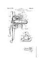
- Fig. 1 is a fragmentary side elevational view of a concrete mixer of the tilting drum present invention ap-. plied thereto.
- Fig. 2 is a detail front elevational view of the stationary lockingmember.
- Fig. 3 is an edge elevational view of the locking member as, seen from the left of Fig. 4 is an enlarged fragmentary sectional detail yiew taken approximately on the plane indicated by the line 4-4 of Fig. 2.
- Fig. 5 is an enlarged assembled sectional view of the locking mechanism taken approximately onthe plane indicated by'the line 55of Fig. 1, and V Fig. 6 is a detail front elevational view of the slidable pinion or gear which engages the stop member shown in Figs. 2 and'3 for performing the locking operation.
- the numeral 10 indicates generally the frame of aconcrete mixer in which is journaled for tilting movements the mixing drum 11.
- the drum is adapted to be tilted-about its pivots 12 by means of a gear wheel 13 which is engaged by a pinion orgear 14, which in the present instance is of peculiar construction and is best illustrated in Figs. 5 and 6.
- the said pinion comprises a hub portion 15 upon which the gear teeth 16 are cut and which is provided at one end with a flange 17 which maybe substantially triangular shape as .22, which may be provided with elongated openings 23 for receiving the securing bolts by means of which it is attached to the frame, the purpose of the 'said'elongated openings being to permit of arcuateadjustment of the
- the member 22 is provided With a bore 24 which receives a pin or stud 25, provided with an enlarged bearing portion '26, upon which the pinion 14 is rotatably and slidably mountsuitable locking nuts '27 as shown in Fig. 5.
- the opposite projecting end of thestud 25 is I threaded as indicated at 28, which threads .100
- a nut 29 having a flange which is received in the recess 18 of the pinion 14, as shown in Fig. 5.
- the flange 30 is positioned between the flange portion 17 of the pinion and the face of the hub 20 of the hand wheel 21, whereby there is provided a connection between the nut 29 and the assembled pinion and hand wheel which permits of relative rotary motion between the nut and the other parts, but which causes any axial movement of the nut to be transmitted to the pinion and wheel.
- the nut 29 is further provided with the rigid handle 31 by means of which it may be manually rotated as will be more fully described below.
- the face of the stop plate 22 is provided with a plurality of recesses 32, concentrically arran ed around the bore 24, which recesses are of such shape and so positioned as to receive the end portions of the teeth 16 of the gear or pinion 14. These end portions are preferably bevelled as indicated at 33 to facilitate the entry of the said teeth into the recesses as will be readily understood.
- Fig. 1 the mixing drum 11 is illustrated in its material-receiving and mixing position.
- the handle 31 of the nut 29 is manually operated to rotate the nut in the proper direction to cause the latter to move axially inwardly upon the stud 25, which motion will, through engagement of the nut with the pinion 14, cause an axial movement of the latter together with the hand wheel 21, so as to bring the bevelled end portions 33 of the pinion teeth 16 into the recesses 32 of the stop plate 22.
- a lock for the tilting drums of concrete mixers which are provided with means including a train of constantly meshed gears for tilting said drum, comprising a recessed stop member adapted to be secured to the frame of the mixer; and screw threaded means for moving one of said gears to bring its teeth into and out of engagement with the recesses of said stop member to prevent and permit tilting movements of said drum said gear remaining in either engaged or disengaged position at will.
- a lock for the tilting drums of concrete mixers which are provided with means including a train of constantly meshed gears for tilting said drum, comprising a stop plate having a plurality of recesses, adapted to be secured to the frame of the mixer; a stud constituting a journal for one of said gears projecting from said plate and provided with a threaded end; and a nut coacting with the threaded end of said stud for sliding said gear thereon to bring its teeth into and out of engagement with the recesses of said stop plate and thereby prevent or permit the-tiltingi'novement of said drum said gear remaining in either engaged or disengaged position at will.
- a lock for the drums of concrete mixers of the tilting-drum type which are provided with means including a gear for tilting said drum, comprising a stop plate having a lurality of recesses, adapted to be secur to the frame of the mixer; a stud having a threaded portion, projecting from said plate; a pinion having a flange rotatably and slida-bly mounted on said stud, with its teeth engaging those of said drum-tilting gear; a manually operable member having a hub seemed to the flange of said pinion; and a flanged nut engaging the threaded portion of saidv stud,thc flange of said nut being disposed between said hub and the flange of.
- said pinion whereby it may cause the sliding of said pinion upon said stud to bring the end portions of its teeth into and out of engagement with the recesses of said stop plate to prevent or permit the tilting move-.
- a lock for the tilting drums of concrete mixers which are provided with means for tilting said drum including a constantly meshing train of gears and means for rotating one of said gears, comprising a recessed stop recesses of said stop member, said 'gear'ree maining 1 in either engaged or disengaged position at will, and constantly meshed with its companion gear.
Landscapes
- Engineering & Computer Science (AREA)
- Mechanical Engineering (AREA)
- Structural Engineering (AREA)
- Preparation Of Clay, And Manufacture Of Mixtures Containing Clay Or Cement (AREA)
Description
April 12, 1932" c BALL 1,853,110
LOCK FOR TILTING DRUM CONCRETE MIXERS Filed Dec. 11, 1928 2 Sheets-Sheet 1 HE "x L "it;
' INVENTOR. ChanleS F301],
Arming:
April 12 1932. c F BALL 1,853,1 10
LOCK FOR TILTING DRUM CONCRETE MIXERS Filed Dec. 11, 19 28 2 Sheets-Sheet 2 INVENTOR. Cfiarlas 17B A TTORNE V1.5
Patented: Apr. 12, 1932 UNITED STATES-l PATE T oriice CHARLES F. BALL, OF MILWAUKEE, WISCONSIN, ASSIGNOR TO CHAIN BELT COM PANY, OFJMILWAUKEE, WISCONSIN, A CORPORATION OF WISCONSIN type illustrating the Fig. 2. V
LOCKFORiTILTING DRUM CONCRETE MIXERS Application filed December 11,1928. ,Serial No. 325,347.
, This inventionrelates to concrete mixers, and more especially to mixers of the tilting drum type, and'has for its principal object the provision of a simple and eifective means for locking the drum against tiltingvmovements in either its mixing or its discharge posit on.
In one form of the well known tilting drum mixers the tilting. movements are accom-. .plished through a train of gears which may be actuatedthrough the medium of a hand wheel, and the present invention conteme stationary stop member carried by the frame .of the machine, it, being understood of course that when the gear teeth are in engagement with the stop member rotation of the gear will be prevented with consequent locking of o the drum against tilting movements.
The ends of the gear teeth are preferably beveled in order to facilitate their engagement with the stop member. 7
With the above and other objects in view, which will appear as the description proceeds, the invention'consists of the novel details" of construction, combinations and arrangements of parts more fully hereinafter described and particularly pointed out in theappended claims.
Referring. to the accompanying drawings forming a part of this specification in which like reference characters designate like parts in allithe views:
Fig. 1 is a fragmentary side elevational view of a concrete mixer of the tilting drum present invention ap-. plied thereto.
Fig. 2 is a detail front elevational view of the stationary lockingmember. Fig. 3 is an edge elevational view of the locking member as, seen from the left of Fig. 4 is an enlarged fragmentary sectional detail yiew taken approximately on the plane indicated by the line 4-4 of Fig. 2.
Fig. 5 is an enlarged assembled sectional view of the locking mechanism taken approximately onthe plane indicated by'the line 55of Fig. 1, and V Fig. 6 is a detail front elevational view of the slidable pinion or gear which engages the stop member shown in Figs. 2 and'3 for performing the locking operation.
In the said drawings the numeral 10 indicates generally the frame of aconcrete mixer in which is journaled for tilting movements the mixing drum 11. The drum is adapted to be tilted-about its pivots 12 by means of a gear wheel 13 which is engaged by a pinion orgear 14, which in the present instance is of peculiar construction and is best illustrated in Figs. 5 and 6. That is to sa'y the said pinion comprises a hub portion 15 upon which the gear teeth 16 are cut and which is provided at one end with a flange 17 which maybe substantially triangular shape as .22, which may be provided with elongated openings 23 for receiving the securing bolts by means of which it is attached to the frame, the purpose of the 'said'elongated openings being to permit of arcuateadjustment of the The member 22 is provided With a bore 24 which receives a pin or stud 25, provided with an enlarged bearing portion '26, upon which the pinion 14 is rotatably and slidably mountsuitable locking nuts '27 as shown in Fig. 5.
The opposite projecting end of thestud 25 is I threaded as indicated at 28, which threads .100
are engaged by a nut 29 having a flange which is received in the recess 18 of the pinion 14, as shown in Fig. 5. As will be clear from the said figure the flange 30 is positioned between the flange portion 17 of the pinion and the face of the hub 20 of the hand wheel 21, whereby there is provided a connection between the nut 29 and the assembled pinion and hand wheel which permits of relative rotary motion between the nut and the other parts, but which causes any axial movement of the nut to be transmitted to the pinion and wheel. The nut 29 is further provided with the rigid handle 31 by means of which it may be manually rotated as will be more fully described below.
The face of the stop plate 22 is provided with a plurality of recesses 32, concentrically arran ed around the bore 24, which recesses are of such shape and so positioned as to receive the end portions of the teeth 16 of the gear or pinion 14. These end portions are preferably bevelled as indicated at 33 to facilitate the entry of the said teeth into the recesses as will be readily understood.
The operation of the invention will be clear from the foregoing, but it may be briefly summarized as follows:
In Fig. 1 the mixing drum 11 is illustrated in its material-receiving and mixing position. In order to maintain the drum in this position against any possibility of tilting about its pivots 12 during the charging and mixing operation, the handle 31 of the nut 29 is manually operated to rotate the nut in the proper direction to cause the latter to move axially inwardly upon the stud 25, which motion will, through engagement of the nut with the pinion 14, cause an axial movement of the latter together with the hand wheel 21, so as to bring the bevelled end portions 33 of the pinion teeth 16 into the recesses 32 of the stop plate 22. It thus follows that the pinion 14 is locked against rotation, and since its teeth are still in engagement with the teeth of the gear 13, the latter gear is also looked and the drum 11 carried by the pivots 12 on which the gear 13 is mounted is likewise locked. The parts are now in the positions illustrated in Fig. 5 and remain in such positions until the mixing operation is completed, whereupon by a reverse movement of the handle 31 the nut 29 will be moved toward the left as viewed in Fig. 5, thereby withdrawing the teeth of the pinion 14 from engagement with the recesses 32 of the stop plate, whereupon the said pinion may be rotated by means of the hand wheel 21 and its motion transmitted through the gear 13 to the drum 11,
and the mixing positions, by simply manipulating the handle 31 as above described.
While one form of the invention has been illustrated and described, it is obvious that those skilled in the art may vary the details of construction as well as the precise arrangement of the parts, without departing from the spirit of the invention, and therefore it is not wished to be limited to the above disclosure, exce t as may be required by the claims.
WV at is claimed 1s:
1. A lock for the tilting drums of concrete mixers which are provided with means including a train of constantly meshed gears for tilting said drum, comprising a recessed stop member adapted to be secured to the frame of the mixer; and screw threaded means for moving one of said gears to bring its teeth into and out of engagement with the recesses of said stop member to prevent and permit tilting movements of said drum said gear remaining in either engaged or disengaged position at will.
2. A lock for the tilting drums of concrete mixers which are provided with means including a train of constantly meshed gears for tilting said drum, comprising a stop plate having a plurality of recesses, adapted to be secured to the frame of the mixer; a stud constituting a journal for one of said gears projecting from said plate and provided with a threaded end; and a nut coacting with the threaded end of said stud for sliding said gear thereon to bring its teeth into and out of engagement with the recesses of said stop plate and thereby prevent or permit the-tiltingi'novement of said drum said gear remaining in either engaged or disengaged position at will.
3. A lock for the drums of concrete mixers of the tilting-drum type which are provided with means including a gear for tilting said drum, comprising a stop plate having a lurality of recesses, adapted to be secur to the frame of the mixer; a stud having a threaded portion, projecting from said plate; a pinion having a flange rotatably and slida-bly mounted on said stud, with its teeth engaging those of said drum-tilting gear; a manually operable member having a hub seemed to the flange of said pinion; and a flanged nut engaging the threaded portion of saidv stud,thc flange of said nut being disposed between said hub and the flange of.
said pinion, whereby it may cause the sliding of said pinion upon said stud to bring the end portions of its teeth into and out of engagement with the recesses of said stop plate to prevent or permit the tilting move-.
ment of said drum.
4. A lock for the tilting drums of concrete mixers which are provided with means for tilting said drum including a constantly meshing train of gears and means for rotating one of said gears, comprising a recessed stop recesses of said stop member, said 'gear'ree maining 1 in either engaged or disengaged position at will, and constantly meshed with its companion gear.
In testimony whereof I aflix my signature. 1 CHARLES F. BALL.
Priority Applications (1)
| Application Number | Priority Date | Filing Date | Title |
|---|---|---|---|
| US325347A US1853110A (en) | 1928-12-11 | 1928-12-11 | Lock for tilting drum concrete mixers |
Applications Claiming Priority (1)
| Application Number | Priority Date | Filing Date | Title |
|---|---|---|---|
| US325347A US1853110A (en) | 1928-12-11 | 1928-12-11 | Lock for tilting drum concrete mixers |
Publications (1)
| Publication Number | Publication Date |
|---|---|
| US1853110A true US1853110A (en) | 1932-04-12 |
Family
ID=23267506
Family Applications (1)
| Application Number | Title | Priority Date | Filing Date |
|---|---|---|---|
| US325347A Expired - Lifetime US1853110A (en) | 1928-12-11 | 1928-12-11 | Lock for tilting drum concrete mixers |
Country Status (1)
| Country | Link |
|---|---|
| US (1) | US1853110A (en) |
Cited By (5)
| Publication number | Priority date | Publication date | Assignee | Title |
|---|---|---|---|---|
| US5148754A (en) * | 1991-03-11 | 1992-09-22 | Tab Products Company | Carriage lock for a mobile storage system with rotatable actuator knob |
| US20030208957A1 (en) * | 2002-05-09 | 2003-11-13 | Robert Meurer | Portable tree pod structure |
| US20080022909A1 (en) * | 2006-07-26 | 2008-01-31 | Grant Matthew M | Sewing machine clutch with removable locking pin |
| GB2463003A (en) * | 2008-08-20 | 2010-03-03 | Eric Chiganel Harris | Barrel Mixer |
| US20120224449A1 (en) * | 2011-03-02 | 2012-09-06 | Eric Harris | Barrel mixer angle adjuster |
-
1928
- 1928-12-11 US US325347A patent/US1853110A/en not_active Expired - Lifetime
Cited By (7)
| Publication number | Priority date | Publication date | Assignee | Title |
|---|---|---|---|---|
| US5148754A (en) * | 1991-03-11 | 1992-09-22 | Tab Products Company | Carriage lock for a mobile storage system with rotatable actuator knob |
| US20030208957A1 (en) * | 2002-05-09 | 2003-11-13 | Robert Meurer | Portable tree pod structure |
| US20080022909A1 (en) * | 2006-07-26 | 2008-01-31 | Grant Matthew M | Sewing machine clutch with removable locking pin |
| US7438009B2 (en) * | 2006-07-26 | 2008-10-21 | Sailrite Enterprises, Inc. | Sewing machine clutch with removable locking pin |
| GB2463003A (en) * | 2008-08-20 | 2010-03-03 | Eric Chiganel Harris | Barrel Mixer |
| GB2463003B (en) * | 2008-08-20 | 2012-03-28 | Eric Harris | Barrel mixer adjustment means |
| US20120224449A1 (en) * | 2011-03-02 | 2012-09-06 | Eric Harris | Barrel mixer angle adjuster |
Similar Documents
| Publication | Publication Date | Title |
|---|---|---|
| US2520443A (en) | Planetary gear speed wrench | |
| US1853110A (en) | Lock for tilting drum concrete mixers | |
| US1643538A (en) | Closure-securing device | |
| US1975961A (en) | Clutch mechanism | |
| US1830840A (en) | Clutch shifting mechanism | |
| US2770339A (en) | Lever hoist | |
| US1442902A (en) | Door-operating mechanism | |
| US1027313A (en) | Reversing-gearing. | |
| US2669486A (en) | Fastening means for demountable wheels | |
| US2710543A (en) | Control mechanism for gears and the like | |
| US1365826A (en) | Face-plate-loosening device for lathes | |
| US1582048A (en) | Concrete-mixing machine | |
| US1847112A (en) | Interlocking mechanism | |
| US1887991A (en) | Camera | |
| US1813242A (en) | Airport closure device | |
| US1374673A (en) | Safety device for car-door-operating mechanisms | |
| US2121095A (en) | Combined clutch and friction retarding means for hand brakes | |
| US1994657A (en) | Hand brake | |
| US1891598A (en) | Rope winding device | |
| US1530178A (en) | Film-feed mechanism for cinematographs | |
| US1488684A (en) | Shaft-operating mechanism | |
| DE915078C (en) | Lid lock on centrifuges | |
| US1907418A (en) | Motion-reversing means | |
| US2462183A (en) | Ratchet and pawl mechanism for hand brakes | |
| US35883A (en) | Improvement in converting motion |