US1853088A - Beam-compass and measuring device - Google Patents
Beam-compass and measuring device Download PDFInfo
- Publication number
- US1853088A US1853088A US372046A US37204629A US1853088A US 1853088 A US1853088 A US 1853088A US 372046 A US372046 A US 372046A US 37204629 A US37204629 A US 37204629A US 1853088 A US1853088 A US 1853088A
- Authority
- US
- United States
- Prior art keywords
- sliding
- sliding member
- instrument
- compass
- screw
- Prior art date
- Legal status (The legal status is an assumption and is not a legal conclusion. Google has not performed a legal analysis and makes no representation as to the accuracy of the status listed.)
- Expired - Lifetime
Links
- 238000007373 indentation Methods 0.000 description 4
- 238000006073 displacement reaction Methods 0.000 description 2
- 238000004519 manufacturing process Methods 0.000 description 2
- 238000005452 bending Methods 0.000 description 1
- 150000001768 cations Chemical class 0.000 description 1
- 238000010276 construction Methods 0.000 description 1
- 230000007423 decrease Effects 0.000 description 1
- 238000000034 method Methods 0.000 description 1
- 238000012986 modification Methods 0.000 description 1
- 230000004048 modification Effects 0.000 description 1
- 230000035945 sensitivity Effects 0.000 description 1
Images
Classifications
-
- B—PERFORMING OPERATIONS; TRANSPORTING
- B43—WRITING OR DRAWING IMPLEMENTS; BUREAU ACCESSORIES
- B43L—ARTICLES FOR WRITING OR DRAWING UPON; WRITING OR DRAWING AIDS; ACCESSORIES FOR WRITING OR DRAWING
- B43L9/00—Circular curve-drawing or like instruments
- B43L9/02—Compasses
- B43L9/04—Beam compasses
Definitions
- the object of invention is to provide a beaminstrument that-may be adapted to be used as a drawing instrument as for instance a beam compass or as a measuring instrumentlike a Vernier-gage inside or outslde calipers or other similar purpose, that can be relatively cheaplymanufactured, al-
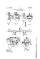
- FIG. 1 is a side-view of Fig. 2, both showring one form embodying. the principles of my invention in connection with a beam of rectangular cross-sectlon. 1g. 3 1s a side,-
- FIG. 4 shows another applia cation of the principles of my invention in r connectionwith abeam of circular cross-section.
- Fig. is anarrangement of another form of application: of my invention in connectlon with abeam of squarecross-section.
- FIG. 6 an enlarged elevation of one ofthe sliding members with beam shown in Fig. '5 and Fig. 7 is a: side-view ofFig. 6.
- Fig. 8 a1 1 other two sides and thecorresponding surfaces of the beam. Inreces'ses -12, friction members 5, (land 7 are inserted, these frictionmembers being preferably made of flexible material and are held against longitudi:
- thefriction members 5, '6 and 7 may be brought in as close frictional contact with beam 1 as desired, thereby eliminating all rocking mo tion of-thesliding member on the beam, so essential for the satisfactory performance of this type of instrument and bringing about the same result as ifv the sliding-member 2, had been accurately fitted to all four sides 5 of the beam 1. It will also be seen, that although all rocking movement can be eliminatedby-such adjustments, it will readily permit of placing the sliding. member into any position upon the beam by merely sliding it there without the necessity of tightening or loosening.
- sliding member 22 and 25 are exactly alike except they are right hand and left hand, and by describing one, the other will be likewise understood.
- a pressure plate 23, of semiflexible material, is secured to sliding-member 22 by screws 2a.
- This pressure plate 23 is arranged to force the beam 20 onto the corresponding surfaces of the sliding member 22 and screws 26 and 27 serve to permit adjustment of the pressure with which the sliding member 22 and the beam 20, are brought in frictional contact with each other.
- screw 26 is of the ordinary kind
- screw 27 is shouldered. It has a. small diameter 28 threaded on one end, and a threaded larger diameter 29.
- the beam 20 is provided with teeth on all four corners formed by the intersection of the four fiat longitudinal sides. These teeth are parts of a helical thread cut with a threading die, a method, that decreases the cost of making such teeth considerably and which can be applied to any beam of suitable cross-section. With these teeth meshes pinion 31, the shaft extension 32 of which has rigidly mounted thereon a finger-wheel 33. A Vernier-plate 34 is secured to sliding member 22, to register with a scale or scales on the beam 20.
- the pressure plate 23 is adjusted by the screws 26 and, 27 to prevent any rocking motion on the beam and to suit the sensitivity of the user, but allowing the sliding member 22 to be positioned readily anywhere upon the beam by merely sliding it, while by means of operating fingerwheel 33 and thereby pinion 31, the sliding member 22 may be placed exactly where desired by observing the scale and Vernier. If the instrunce is used as a beam compass, there is rarely a necessity to permanently fasten the sliding member to the beam.
- the knurled nut 30 may be screwed up tightly against the pressure-plate 23, thus bringing the beam 20 and the sliding member 22 into such close frictional contact as to preclude any movement of the one upon the other.
- the handle 39 is provided, which is slidably clamped to the beam 20 as shown in Fig. 5, so it may be readily removed if the beam 20 is used for either purposes.
- Fig. 5 shows the sliding members 22 and 23 equipped with slotted holes 36 into which numerous attachments for drawing or measuring may be clamped by the stationary screw 37 and the knurled nut 38, but it will be understood the sliding member 22 may be so designed as to suit only a single purose;
- An instrument of the class described the sliding member whereof is loosely fitting upon a beam and having adjustable means to bring the sliding member and the beam into close frictional contact with each other, thereby el minating rocking movement of the sliding. member around the axis of the beam and rocking movement of the sliding member lengthwise of the beam, but permitting of ready adjustment and readjustment of the sliding-member by sliding in a longitudinal direction of and on the beam.
- sliding memberwhereof is loosely fitting, upon a vbeamand having adjustable; means to bring said sliding-member and said beam into close frictional; contact With'each other and ;.other means; cooperating. with above mentioned adjustable means tomore firmly secure orlockesaid sliding-member to it said beam, said other means reestablishing the frictional relations existing between said s1id-. ing-memberand said beam when made-inoperative.
- An instrumentof the class described the beam of which is provided with indentations or teeth on one or moreof its corners 'jformed by the intersection-0f its flat surfaces adapted to be usedefor instruments of the class described, having indentations or teeth out in one or more-of its corners the latter formed by-the intersection of the longitudinal surfaces of said beam.
- a beam for an instrument of the classdescribed, with indentations or teeth out in one or more of its corners, the latter formed by the intersection of the longitudinal surfaces of said beam, said 7 longitudinal surfaces being provided with oneor more scales for the purpose set forth.
- MAX SIDONQ which is parallel with the longitudinal axis i i
Landscapes
- Measurement Of Radiation (AREA)
Description
April 12, 1932. M. smoN BEAM COMPASS AND MEASURING DEVICE Filed June 19, 1929 Fig.l
INVENTOR.
I Patented Apr. 12,1932:
MAX SIDON'; or woons rnn vnw YORK nnsmcoirrass AND 'liIEASUBING .nnvrcn,
' App1icati0n ifi ed June 19', 1929. Serial 110,372,046.
claimed.
The object of invention is to provide a beaminstrument that-may be adapted to be used as a drawing instrument as for instance a beam compass or as a measuring instrumentlike a Vernier-gage inside or outslde calipers or other similar purpose, that can be relatively cheaplymanufactured, al-
though capable of highly satisfactory results and that can be quickly andaccurately adjusted as hereinafterv fully described and .My' invention is illustrated in the, accompanying drawings, wherein- I Fig. 1 is a side-view of Fig. 2, both showring one form embodying. the principles of my invention in connection with a beam of rectangular cross-sectlon. 1g. 3 1s a side,-
viewof Fig. 4, both showing another applia cation of the principles of my invention in r connectionwith abeam of circular cross-section. Fig. is anarrangement of another form of application: of my invention in connectlon with abeam of squarecross-section.
Fig. 6 an enlarged elevation of one ofthe sliding members with beam shown in Fig. '5 and Fig. 7 is a: side-view ofFig. 6. Fig. 8 a1 1 other two sides and thecorresponding surfaces of the beam. Inreces'ses -12, friction members 5, (land 7 are inserted, these frictionmembers being preferably made of flexible material and are held against longitudi:
nal displacement by angular extensions 8.
a The friction members. -6 and 7 are forced against the beamll by adjustable screws 9, while friction member 5 is. similarly acted upon by the tapped and knurled screw 10.
Into the tapped hole of knurled screw'lO fits the knurled screw 11. It will be noted, that by adjusting the screws 9 and 10, thefriction members 5, '6 and 7 may be brought in as close frictional contact with beam 1 as desired, thereby eliminating all rocking mo tion of-thesliding member on the beam, so essential for the satisfactory performance of this type of instrument and bringing about the same result as ifv the sliding-member 2, had been accurately fitted to all four sides 5 of the beam 1. It will also be seen, that although all rocking movement can be eliminatedby-such adjustments, it will readily permit of placing the sliding. member into any position upon the beam by merely sliding it there without the necessity of tightening or loosening. any screws before or after the sliding member has been repositioned upon the beam. Sliding members, thus slidably arranged onthe beam will not become dis-.- e5 placed when the instrument is used as a dra ing instrument or inside or outside calipers i. e. if pressure is applied on the sliding members some distance away from the beam.
. However, if it should lie-desirable to lock the sliding member. to the beam the screw 11 may be applied to force friction-member 5 with suflicient pressure against the beam to bring about this effect; p If screw 11 is retractedthe pressure of the friction-member 5 against thebeam 1 that: obtainedbefore will be reestablished and the slidingmembermay bereadjusted on the, beam as explained. i
Referring'to Figures 3 and 4: asimilar cf, 30 feet is produced as above described in ,connection with: a round bar 13, provided with a fiat surface 14, upon which is slidably arranged the member 15, carrying ina recess 7 the friction member 16, the latter being .prevented from longitudinal displacement by the angular extensions 17. The tappedknurled screw 18 serves toforce the friction member 16 against the flat surface 14: of beam 13, with any desired pressure while the knurled screw 19 acts asset-screw. v I In Figures 5, 6, 7 .and8 is illustrated another application of my invention. v l lnthis instance lam usinga square beam,
edgewise i. e. with vFtwo diametrically opposite edges in a verticalposition, because its cross-section f is strongest against bending; when placed in this position and for 'construc- .1 tional reasons, which will become apparent I later; Sliding members 22 and 25 are shaped .19
to fit a square beam 20 on two sides only. These sliding members 22 and 25 are exactly alike except they are right hand and left hand, and by describing one, the other will be likewise understood. Thus, I will describe sliding member 22 as illustrated in Figures 6 and 7. A pressure plate 23, of semiflexible material, is secured to sliding-member 22 by screws 2a. This pressure plate 23 is arranged to force the beam 20 onto the corresponding surfaces of the sliding member 22 and screws 26 and 27 serve to permit adjustment of the pressure with which the sliding member 22 and the beam 20, are brought in frictional contact with each other. It will be noted, that while screw 26 is of the ordinary kind, screw 27 is shouldered. It has a. small diameter 28 threaded on one end, and a threaded larger diameter 29. On the larger diameter 29 fits the knurled nut 30, for the purpose explained later. The beam 20 is provided with teeth on all four corners formed by the intersection of the four fiat longitudinal sides. These teeth are parts of a helical thread cut with a threading die, a method, that decreases the cost of making such teeth considerably and which can be applied to any beam of suitable cross-section. With these teeth meshes pinion 31, the shaft extension 32 of which has rigidly mounted thereon a finger-wheel 33. A Vernier-plate 34 is secured to sliding member 22, to register with a scale or scales on the beam 20.
When using this instrument, the pressure plate 23 is adjusted by the screws 26 and, 27 to prevent any rocking motion on the beam and to suit the sensitivity of the user, but allowing the sliding member 22 to be positioned readily anywhere upon the beam by merely sliding it, while by means of operating fingerwheel 33 and thereby pinion 31, the sliding member 22 may be placed exactly where desired by observing the scale and Vernier. If the instrumment is used as a beam compass, there is rarely a necessity to permanently fasten the sliding member to the beam. However, when used as a measuring instrument it is desirable to do so and for this reason the knurled nut 30 may be screwed up tightly against the pressure-plate 23, thus bringing the beam 20 and the sliding member 22 into such close frictional contact as to preclude any movement of the one upon the other.
By unscrewing the knurled nut 30 the frictional relation between the beam 20 and the sliding member 22 existing before said knurled nut 20 was applied will be reestablished and the sliding member 22 may again be slid on said beam 20 without any readjustment of the pressure-plate 23 being necessary to eliminate any rocking motion of the sliding-member 22 on beam 20.
' To facilitate rotating the instrument when used as a compass, particularly to draw smaller circles, the handle 39 is provided, which is slidably clamped to the beam 20 as shown in Fig. 5, so it may be readily removed if the beam 20 is used for either purposes.
Fig. 5 shows the sliding members 22 and 23 equipped with slotted holes 36 into which numerous attachments for drawing or measuring may be clamped by the stationary screw 37 and the knurled nut 38, but it will be understood the sliding member 22 may be so designed as to suit only a single purose;
While I have described in detail some forms, constructions and arrangements of my invention, it is evident many other modifications may be made to conform to specific requirements without departing from the spirit of my invention, and I therefore do not limit myself to those shown.
What I claim as new and desire to secure by Letters Patent, is: l
1. An instrument of the class described the sliding member whereof is loosely fitting upon a beam and having adjustable means to bring the sliding member and the beam into close frictional contact with each other, thereby el minating rocking movement of the sliding. member around the axis of the beam and rocking movement of the sliding member lengthwise of the beam, but permitting of ready adjustment and readjustment of the sliding-member by sliding in a longitudinal direction of and on the beam.
2. An instrument of the class described the sliding member whereof is loosely fitting upon a beam and having adjustable means to bring the sliding member and thebeam into close frictional contact with each other, thereby eliminating rocking movement of the sliding member around the axis of the beam and rocking movement of the sliding member lengthwise of the beam but permitting adjustment and readjustment of the slidingmember by sliding in a longitudinal direction of and onthe beam without the necessity of changing the frictional relation of the sliding member with the beam, before or after the adjustment has been made.
3. An instrument of the class described, the sliding member whereof is loosely fitting upon a beam and having adjustable means to bring said sliding-member and said beam into close frictional contact with each other thereby eliminating rocking movement of said sliding-member around the axis of said beamand rocking movement of said slidingmember lengthwise of said beam but permit ting adjustment and readjustment of said sliding member by sliding in a longitudinal direction of and on said beam without the necessity of changing the frictional relation of said sliding member with the said beam, before or after the adjustment has been made, and other means to more firmly secure or lock the said sliding member on said beam,
4. An instrument of the class described, the
sliding memberwhereof is loosely fitting, upon a vbeamand having adjustable; means to bring said sliding-member and said beam into close frictional; contact With'each other and ;.other means; cooperating. with above mentioned adjustable means tomore firmly secure orlockesaid sliding-member to it said beam, said other means reestablishing the frictional relations existing between said s1id-. ing-memberand said beam when made-inoperative.
5. An instrumentof the class described,.' the beam of which is provided with indentations or teeth on one or moreof its corners 'jformed by the intersection-0f its flat surfaces adapted to be usedefor instruments of the class described, having indentations or teeth out in one or more-of its corners the latter formed by-the intersection of the longitudinal surfaces of said beam. e
8. As a new article of manufacture, a beam, for an instrument of the classdescribed, with indentations or teeth out in one or more of its corners, the latter formed by the intersection of the longitudinal surfaces of said beam, said 7 longitudinal surfaces being provided with oneor more scales for the purpose set forth.
9. As a new article of manufacture a beam,
the corners of whichfare provided with in dentation or teeth, said corners being formed l by the intersection ofthe longitudinal sur-' faces of said beam, said indentation'or teeth e being portions ofahelix'the centerline of of, said beam;
MAX SIDONQ which is parallel with the longitudinal axis i i
Priority Applications (1)
| Application Number | Priority Date | Filing Date | Title |
|---|---|---|---|
| US372046A US1853088A (en) | 1929-06-19 | 1929-06-19 | Beam-compass and measuring device |
Applications Claiming Priority (1)
| Application Number | Priority Date | Filing Date | Title |
|---|---|---|---|
| US372046A US1853088A (en) | 1929-06-19 | 1929-06-19 | Beam-compass and measuring device |
Publications (1)
| Publication Number | Publication Date |
|---|---|
| US1853088A true US1853088A (en) | 1932-04-12 |
Family
ID=23466475
Family Applications (1)
| Application Number | Title | Priority Date | Filing Date |
|---|---|---|---|
| US372046A Expired - Lifetime US1853088A (en) | 1929-06-19 | 1929-06-19 | Beam-compass and measuring device |
Country Status (1)
| Country | Link |
|---|---|
| US (1) | US1853088A (en) |
Cited By (3)
| Publication number | Priority date | Publication date | Assignee | Title |
|---|---|---|---|---|
| US2833041A (en) * | 1956-04-26 | 1958-05-06 | Leo J Reno | Dual scriber |
| US3154859A (en) * | 1962-03-26 | 1964-11-03 | Monitor Tool & Finding Co | Measuring device |
| US3872737A (en) * | 1972-05-19 | 1975-03-25 | Thomas Hazel Beasley | Selector for a transmission |
-
1929
- 1929-06-19 US US372046A patent/US1853088A/en not_active Expired - Lifetime
Cited By (3)
| Publication number | Priority date | Publication date | Assignee | Title |
|---|---|---|---|---|
| US2833041A (en) * | 1956-04-26 | 1958-05-06 | Leo J Reno | Dual scriber |
| US3154859A (en) * | 1962-03-26 | 1964-11-03 | Monitor Tool & Finding Co | Measuring device |
| US3872737A (en) * | 1972-05-19 | 1975-03-25 | Thomas Hazel Beasley | Selector for a transmission |
Similar Documents
| Publication | Publication Date | Title |
|---|---|---|
| US964785A (en) | Combination instrument. | |
| US1853088A (en) | Beam-compass and measuring device | |
| US2426583A (en) | Flexometer testing device | |
| US2328517A (en) | Movable position finding devices, particularly course protractors | |
| US2080792A (en) | Scale section liner | |
| US1753191A (en) | Combination rule gauge | |
| US1852485A (en) | Beam-compass and measuring device | |
| US4175330A (en) | Adjustable compass device | |
| US923313A (en) | Mechanic's tool. | |
| US2297999A (en) | Compass | |
| US897437A (en) | Calipers. | |
| US939597A (en) | Beam-compass. | |
| US759239A (en) | Instrument for measuring angles. | |
| US1172463A (en) | Tape attachment. | |
| US1485154A (en) | Gauge | |
| US2412084A (en) | Protractor | |
| US3238625A (en) | Angulator | |
| US2543026A (en) | Center punch gauge | |
| US1586067A (en) | Drawing board | |
| US399167A (en) | Micrometer caliper-square | |
| US3925900A (en) | Counter system for step-and-repeat drafting arm | |
| US2507961A (en) | Reversible adjustable checking gauge | |
| US2505015A (en) | Arc scriber | |
| US1127802A (en) | Angle-gage. | |
| US1007229A (en) | Gage. |