US1853082A - Self-stabilizing airship - Google Patents
Self-stabilizing airship Download PDFInfo
- Publication number
- US1853082A US1853082A US523248A US52324831A US1853082A US 1853082 A US1853082 A US 1853082A US 523248 A US523248 A US 523248A US 52324831 A US52324831 A US 52324831A US 1853082 A US1853082 A US 1853082A
- Authority
- US
- United States
- Prior art keywords
- airship
- ship
- air
- stabilizing
- self
- Prior art date
- Legal status (The legal status is an assumption and is not a legal conclusion. Google has not performed a legal analysis and makes no representation as to the accuracy of the status listed.)
- Expired - Lifetime
Links
Images
Classifications
-
- B—PERFORMING OPERATIONS; TRANSPORTING
- B64—AIRCRAFT; AVIATION; COSMONAUTICS
- B64B—LIGHTER-THAN AIR AIRCRAFT
- B64B1/00—Lighter-than-air aircraft
- B64B1/40—Balloons
Definitions
- Serial This invention pertains to self-stabilizing airships. More particularly/it pertains to an airship of the lightersthan-air variety 1 n which provision is made for automatic I stabilization of the ship in response to deviations from a predetermined normal posture.
- One feature of the invention comprises stabilization,; rapidly and efliciently, by
- V V f Figure 1 is aside elevation ofan airship having a system of stabilizing in which bal-' 5 last is shifted'under automatic control;
- Figure 2i is a .side elevation on a larger scale of one of the ballast tanks;
- I Figure 3 is a side elevation also onalarger scale of a motor driven air compressor with i ta11k; v
- Figure 4 is. an end view of theactuatingmember, with air valve; r 1
- FIG. 5 is a sectional view of the actuating-member, on line .55 of Figure 4;
- Figure 6 is a sectional viewof the air valve online 6 6 of Figure 4.
- FIG. 7 is a sectional view of the same on a line 77'of Figure 6.
- the tanks and 36 are connectedto each other by pipe 37 for the flow of liquid and by air pipes 171 and 17 4 tot-he air valve 17 2; From this latter, pipe 176 is an outlet, and pipe 173 runs between the air valve and the compressed air tank 186; Con- .veniently located and connected with this tank is, the compressor 184 driven by motor 185.
- the pipe lines are equipped withl suit- No. 523,248. g I
- a heav'y'actuatingmember 17 9 swings freely in the vertical longitudinal plane of the airship from the shaft 180 to which is also',
- su'pportingframe 177 swings tothe left' as regards the actuating-member, which remains vertical.
- the outer valve piece 1721-otates'in aic'lockwise direction permitting compressed air to pass from the port 173 to :pipe 174' and thence to tank 36; butibeforethis-passage of air takes place; the valve makes a connection between pipe 171 andthe exhaust 176, thus permitting compr'ess'ed'a'in to escape from tank:35'.
Landscapes
- Engineering & Computer Science (AREA)
- Mechanical Engineering (AREA)
- Aviation & Aerospace Engineering (AREA)
- Toys (AREA)
- Jet Pumps And Other Pumps (AREA)
Description
April 12; 1932 W. V. N. POWELSON. ET AL SELF STABILIZING AIRSHIP b riginal Filed Sept! 6, 1921 I lf H w? f y 3 fi 3m; WWW fi rim a Z Patented Apr. l2,i 1932 umrno STATES PATENT orricg winrnrn v, N. rownnson, on NEW yonxg mva AND WARREN sen BERNARDINQ; CALIFORNIA,
TBAVELL, or
sELF-sTABILIzrnei AIn'sHI'r fl Original application filed September a, 1921, Serial No. 498,605; mviaa ahauus application filed ara 17,
1931. Serial This inventionpertains to self-stabilizing airships. More particularly/it pertains to an airship of the lightersthan-air variety 1 n which provision is made for automatic I stabilization of the ship in response to deviations from a predetermined normal posture. One feature of the invention comprises stabilization,; rapidly and efliciently, by
- means of compressed air.' I
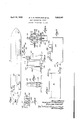
Hitherto, air ships "have not employed stabilizing means, although their advantages have been numerous and obvious, this because the stabilization means hithertoknown have been cumbersome and heavy. The present invention makes possible stabilization by simple apparatus having comparatively little weight and functioning automatically without appreciable lag. I One object of the inventionto stabilize an airship in flight in a simple and eficient way-is thereby attained. In the accompanying drawings, forming apart hereof: V V f Figure 1 is aside elevation ofan airship having a system of stabilizing in which bal-' 5 last is shifted'under automatic control;
Figure 2iis a .side elevation on a larger scale of one of the ballast tanks; I Figure 3 is a side elevation also onalarger scale of a motor driven air compressor with i ta11k; v
Figure 4 is. an end view of theactuatingmember, with air valve; r 1
V Figure 5 is a sectional view of the actuating-member, on line .55 of Figure 4;
Figure 6 is a sectional viewof the air valve online 6 6 of Figure 4; and
' Figure 7 is a sectional view of the same on a line 77'ofFigure 6. o I The several figures of the drawings-show apparatus for stabilizing the airship by shifting liquid, which may be liquid fuel, under automatic "control. The tanks and 36 are connectedto each other by pipe 37 for the flow of liquid and by air pipes 171 and 17 4 tot-he air valve 17 2; From this latter, pipe 176 is an outlet, and pipe 173 runs between the air valve and the compressed air tank 186; Con- .veniently located and connected with this tank is, the compressor 184 driven by motor 185. The pipe lines are equipped withl suit- No. 523,248. g I
able cut-oft valves 182' and check valves 181. A heav'y'actuatingmember 17 9 swings freely in the vertical longitudinal plane of the airship from the shaft 180 to which is also',
fastened the rotor 175 ofthe valve 172., Thefapparatus is simple in its operation andneeds little explanation. When the bow of the airship'is depressed for any reason, the
su'pportingframe 177 swings tothe left' as regards the actuating-member, which remains vertical. Referring to Figure 6, the outer valve piece 1721-otates'in aic'lockwise direction, permitting compressed air to pass from the port 173 to :pipe 174' and thence to tank 36; butibeforethis-passage of air takes place; the valve makes a connection between pipe 171 andthe exhaust 176, thus permitting compr'ess'ed'a'in to escape from tank:35'.
The entrance o fair. into tank 36 and thev escape of air from tank 35"causes-liquid to flow fromitank 36yto tank 35 through theoconinecting, pipe 37, thus shifting weight from i.
the bow to the stern and producing a stabilizirig'! efiect. The reverse of this operation takes place when the stern end ofthje airship isdepressed. These port and exhaust openlngs'are connectedsothat the sizeof the'o en i it ing for passage of air varies with the ampli tude of the swing ofqthe actuating-member. Accordingly the greater the divergence of the airship from its; normal positiom'theflquicker will beth'e action' of the stabilizer toward re"- storing-it to its normal'iposition. Thediamond-shaped-port in the rotor 175, seenin Figure 1, makes this possible.
Obviously modifications may be made from' time to time without departing from the inventive thought. Thus it. is possible to em-. 7 ploy in place of actuatingmember 179 equivalent apparatus serving to control the compressed .air system. Obviouslyanother gas may be employed in place of the. compressed air, although the latter is cheap and entirely suitable. In the, preferred'speciesof the invention the tanks 35, 36are located to ward the extreme ends of the airship, but any position on opposite sidesof a plane passing transversely through the center of the air- 7 j ship will tend to produce the same result. The subject matter of this application has been divided out of our copending application 498,605, filed September 6, 1921 for Airships. It is intended that the patent to be based on the present application shall cover, by suitable expression in the appended claims, whatever features of patentable novelty are contained in the species herein set forth of the eneric invention therein disclosed.
A though the invention is herein described as it may be particularly applied to an airship, it is obvious that it is applicable broadly and with equal effect to any ship wholly immersed in a fluid medium, as, for example, a submarine.
We claim:
1. In equipment for stabilizing a bouyant ship wholly immersed in a fluid medium, the combination with a liquid fuel supply system of the ship of means for automatically transferring liquid fuel from one to another of the various tanks of said system, said tanks being located in differing relation to a medial plane of the ship, whereby the said transfer alters the angle at which the ship tends to come to rest; said transfer means comprising a system of pipes connecting the various tanks, a supply of compressed air, suitable tanks, piping, and valves therefor, and an automatic control actuated by changes in the relative elevation of two of the parts thereof.
2. In equipment for stabilizing a bouyant ship immersed in a fluid, the combination of two tanks for liquid attached to said ship, located in differing relations to a medial plane of the ship, whereby liquid flow from one to the other alters the angle at which the ship tends to come to rest; piping connection for said flow; liquid therein; a supply of compressed air and piping connections for it to control the liquid flow; and an automatic valve actuated by tipping of the ship and having a port With diverging sides whereby the area of valve opening is graduated to increase faster than its linear extent of opening increases with the tipping of the ship.
Signed at San Bernardino, California, this eleventh day of November, 1930.
WILFRID V. N. POWELSON. WARREN TRAVELL.
Priority Applications (1)
| Application Number | Priority Date | Filing Date | Title |
|---|---|---|---|
| US523248A US1853082A (en) | 1921-09-06 | 1931-03-17 | Self-stabilizing airship |
Applications Claiming Priority (2)
| Application Number | Priority Date | Filing Date | Title |
|---|---|---|---|
| US498605A US1853376A (en) | 1921-09-06 | 1921-09-06 | Airship |
| US523248A US1853082A (en) | 1921-09-06 | 1931-03-17 | Self-stabilizing airship |
Publications (1)
| Publication Number | Publication Date |
|---|---|
| US1853082A true US1853082A (en) | 1932-04-12 |
Family
ID=27052883
Family Applications (1)
| Application Number | Title | Priority Date | Filing Date |
|---|---|---|---|
| US523248A Expired - Lifetime US1853082A (en) | 1921-09-06 | 1931-03-17 | Self-stabilizing airship |
Country Status (1)
| Country | Link |
|---|---|
| US (1) | US1853082A (en) |
Cited By (1)
| Publication number | Priority date | Publication date | Assignee | Title |
|---|---|---|---|---|
| US6685137B2 (en) * | 2000-03-16 | 2004-02-03 | Bae Systems Plc | Flight control system for an aircraft |
-
1931
- 1931-03-17 US US523248A patent/US1853082A/en not_active Expired - Lifetime
Cited By (1)
| Publication number | Priority date | Publication date | Assignee | Title |
|---|---|---|---|---|
| US6685137B2 (en) * | 2000-03-16 | 2004-02-03 | Bae Systems Plc | Flight control system for an aircraft |
Similar Documents
| Publication | Publication Date | Title |
|---|---|---|
| US1307135A (en) | Hydroplane, also applicable to hydroaeroplanes. | |
| US1853082A (en) | Self-stabilizing airship | |
| US1511153A (en) | Sea station | |
| US1868054A (en) | Boat and means for operating the same | |
| US1581595A (en) | Valve | |
| GB572413A (en) | Improvements in or relating to high speed water craft | |
| US1729446A (en) | Ship hull | |
| US1693773A (en) | Aircraft pontoon apparatus | |
| US1489619A (en) | Buoyancy equipment for aircraft | |
| US1629843A (en) | Aircraft | |
| US3103198A (en) | Safety arrangement for stabilization system | |
| US1426047A (en) | Airship | |
| US1901173A (en) | Dirigible-airplane | |
| US3504651A (en) | Ship stabilizing system | |
| US1333580A (en) | Floating dry-dock | |
| US2847962A (en) | Salvage apparatus | |
| US1538974A (en) | Water ballast for balloons | |
| US3195497A (en) | Tank stabilizing system for a ship and the like | |
| US1817047A (en) | Airplane pontoon | |
| US1241408A (en) | Bailing-valve. | |
| US1296662A (en) | Dry-dock. | |
| US1306318A (en) | Stabilizer | |
| US888274A (en) | Marine vessel. | |
| US1380575A (en) | Means for automatically registering a ship's draft | |
| US1878723A (en) | Airplane construction |