US1853078A - Apparatus for removing surplus insulation from armature cores - Google Patents
Apparatus for removing surplus insulation from armature cores Download PDFInfo
- Publication number
- US1853078A US1853078A US418975A US41897530A US1853078A US 1853078 A US1853078 A US 1853078A US 418975 A US418975 A US 418975A US 41897530 A US41897530 A US 41897530A US 1853078 A US1853078 A US 1853078A
- Authority
- US
- United States
- Prior art keywords
- brushes
- armature
- work holder
- core
- insulation
- Prior art date
- Legal status (The legal status is an assumption and is not a legal conclusion. Google has not performed a legal analysis and makes no representation as to the accuracy of the status listed.)
- Expired - Lifetime
Links
- 238000009413 insulation Methods 0.000 title description 9
- 241001417494 Sciaenidae Species 0.000 description 1
- ZPUCINDJVBIVPJ-LJISPDSOSA-N cocaine Chemical compound O([C@H]1C[C@@H]2CC[C@@H](N2C)[C@H]1C(=O)OC)C(=O)C1=CC=CC=C1 ZPUCINDJVBIVPJ-LJISPDSOSA-N 0.000 description 1
- 239000011810 insulating material Substances 0.000 description 1
- 238000004519 manufacturing process Methods 0.000 description 1
- 230000000717 retained effect Effects 0.000 description 1
- 238000004804 winding Methods 0.000 description 1
Images
Classifications
-
- H—ELECTRICITY
- H02—GENERATION; CONVERSION OR DISTRIBUTION OF ELECTRIC POWER
- H02K—DYNAMO-ELECTRIC MACHINES
- H02K15/00—Processes or apparatus specially adapted for manufacturing, assembling, maintaining or repairing of dynamo-electric machines
- H02K15/10—Applying solid insulation to windings, stators or rotors, e.g. applying insulating tapes
Definitions
- This invention relates to, the manufacture of armatures for dynamo electric machines andmore especially'to the type of manufac- 7 ture'which includes the steps of insulating a slotted armature corewith a lining of sheet insulating material portions of which may over-lie the peripheries of armature core teeth as well as line. the core slots, of windingzwire 'into' the core slots thus holding the slot insulation'inposition, and then of'removing the surplus insulation which overlies the peripheries of the armature core teeth.
- One of the objects v tion is to provide apparatus for removing the, surplusinsulation'at the peripheries of the. core gteeth, and-in order to accomplish this object the present invention provides a 7 work holder for rotatably supporting an, armature "core and a pair of wire bristle brushes rotatingin opposite directions while simultaneously engaging the core which may be rotated while being engaged by the 'posi'- tivelyrotating wire bristle brushes.
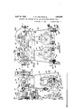
- Fig. ,1 is. a front elevation of'a machine embodying the present invention.
- the part of Fig. 1*shown in'section is takenon the I section line 11 of Fig. 2.
- Fig. 2 is. a side elevation of the machine shown in Fig. 1. 1 The parts shown in section are taken respectively on the section lines 2-2,- 2a-2a' and 2b2b of Fig. 1.
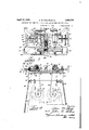
- Fig. 3 isa plan iviewpartly insection taken on'the line33 of Fig.1.
- Fig.4 is afragmentary sectional. view taken on the line 4 4 of Fig. 2.
- FIG.--.5 is a sectional view on the line 5 45 of, Fig. 2., I
- Thesupporting frame of the apparatus comprises a table top 20* attached to channel 3 bars 21 in turn attached to legframes 22 hav-- ing channel cross bars 23 which support two of those shelves '24.
- the table top 20 pro vides dove-tail ways and 31which guide for horizontal sliding movement bearing brackets 32 and 33, respectively which shafts 34 and 35 respectively are journalled.
- the shafts 34 and 35 support and drive rotatablewire bristle brushes 36 and 3 7.
- the base may be moved in'a belts 44 and 45 counterclockwise direction about its pivot 52 in order to'tighten the belt 44 by turning the nuts 54'and 56 down along a bolt 58 attached 'to'a rod 60 having its ends j ournalled in brack ets 62 attached t0 the shelf 24.
- the belt 45 is tightenedin-a similar manner by screwing, nuts "55 and 57 down along abolt 59 attached at its lower end to a cross bolt 61 journalled at its end ,infbracket 63.
- the work holder comprises a block providing a bearing for a rod 71 attached to a member 7 2 providing a socket for a recess 73 for receiving one'end of an armature shaft 74 supporting a core 75 into which windings, 76
- the holdermember 72 provides a cup-shaped head 77 for receiving end of the core and which surround the shaft 74 as viewed in Fig. 3. Normally the head portion 77 is located between the brushes 36 and 37 where it will be readily accessible for receiving an armature core to be operated on by the machine.
- the member 72 is held in this position nearest the front of the machine by a spring 78 located between the work holder block and a thrust bearing 79 surrounding the shank of the work holder member 72 and bearing against a shoulder 80 thereof.
- the outward movement of the work holder 72 is limited by a washer 81, attached to the rod 71 by a nut 82, striking against the work holder block 70.
- the brushes being of the same diameter and rotating at substantially the same speed there will be substantially no tendency for the armaturecore to be rotated due to contact with the brushes; therefore the core may be easily rotated manually.
- the brushes are originally of the same diameter and will remain equal in diameter until worn away since they wear away substantially at an equal rate. It is not intended by Fig. '3 to show that the brushes are of different diameters at the same time. 3 shows-that initially both brushes may have a diameter as large as the diameter of brush 37 in Fig. 3 and may wear down to a diameter as small as that of brush 36 shown in Fig. 3. As the brushes wear away it is necessary to move the brush bearing brackets 32 and 33 closer to the work holder block 7 0.
- Bracket 32 provides a recess for receiving the circular head 91 of a screw 92 which is threaded through a nut 93 carried by a stationarybracket 94 attached by screws 95 to the table 20.
- the head 91 of the screw 92 is retained by a plate 91a having-a hole larger in diameter than the body of the screw 92 and smaller thandts head 91.
- This plate 91a is attached to the bracket 32in any suitable manner.
- the screw 92 carries a hand wheel 96 by which the screw is turned in order to slide the bracket 32 along the way 30 of the table 20.
- bracket 32 After the bracket 32 has been located in the proper position to com ensate for wear of the brush 36 it is clampe in this position to the way 30 by turning the handle 100 of a screw 101 which is threaded into a portion of the bracket 32.
- the handle 100 bears against the bifurcated side extension 102 of a wedge 103 having a surface 104 which is tapering with respect to the surface 105 of the wedge which engages thesurface 106 of the way 30.
- the tapering wedge surface 104 cooperates with a correspondingl taperingsurface 107 of the bracket 32 who is non-parallel with respect to the surface (106 of the way 30.
- the brushes are enclosed by a suitable housing shown in full linesectional views in Figs. 2 and 3 and as a hantom vview by dot and dash lines 130a inI 1.
- the hon ing 130 provides a notch .131 through which the work holder may extend to receiveetbe armature tobe operated 1 upon.
- Apparatusfor removing-surplus insulation from an armature core comprising a pair of parallel shafts'rotatw bly supporting respectively apairof wire bristle brushes, a pair of bracketseach rotatably supporting the shaft, a work holder block located between the shaftbraeketsa rod rotat-ably supported by the hlockand movable axially relative-to the block, an armature receiving work holder attached to said rod and means resiliently urgiw said work holder away from the work holder block into a position between the rotating brushes, and means for rotating the brushes simultaneously in opposite directions.
- Apparatus forremoving-surplus inslflation from. an I armature. core comprising, in combination, asupporting frame,a-table top, a pair of shaft bearing bracketssupported by the table to and guidedby ways provided therein, sair ways locating the brackets -80 that their bearings willz-always be in penallelism and guiding said brackets-formanment in directions at right angles to (the axes of said bearings, shafts supportedlby said bearing brackets and each carrying a rotata ble Wire bristle brush, a work holder for rotatably supporting an armature core between said brushes, means for simultaneously rotating said brushes in opposite directions, de vices for independently adjusting said hearing brackets alongthe table, and devices for, clamping said bearing brackets to the table; in adjusted position.
Landscapes
- Engineering & Computer Science (AREA)
- Manufacturing & Machinery (AREA)
- Power Engineering (AREA)
- Polishing Bodies And Polishing Tools (AREA)
Description
April 1932- A. w. PHELPS ET AL 1,853,978
APPARATUS FOR REMOVING SURPLUS INSULATION F'RQMv ARMATURE CORBS Filed Jan- 6. 1930 2 Sheets-Sheet 1 April 12, 1932. A. w. PHELPS ET AL 1,853,073
APPARATUS FOR REMOVING SURPLUS INSULATION FROM ARMATURE CORES Filed Jan. 6, 1930 2 Shets-Sheet 2 Patented Apr. 12, .1932,
issama I OFFICEY f ALVA 1.4mm AND JOHNQ. HOLMES, or ANDERSON, INDIANA; ASSIGNORS 'ro ,nELco-. 1 i
1 CORPORATION, OF ANDERSON, INDIANA, A CORPORATION OF. DELAWARE I 7 JArrAnATU's ronnnmovnve sunrnus INSULATION snort ARMATURE CORES Application filed January 6, 1930. Serial No. 418,975.
This invention relates to, the manufacture of armatures for dynamo electric machines andmore especially'to the type of manufac- 7 ture'which includes the steps of insulating a slotted armature corewith a lining of sheet insulating material portions of which may over-lie the peripheries of armature core teeth as well as line. the core slots, of windingzwire 'into' the core slots thus holding the slot insulation'inposition, and then of'removing the surplus insulation which overlies the peripheries of the armature core teeth.
One of the objects v tion is to provide apparatus for removing the, surplusinsulation'at the peripheries of the. core gteeth, and-in order to accomplish this object the present invention provides a 7 work holder for rotatably supporting an, armature "core and a pair of wire bristle brushes rotatingin opposite directions while simultaneously engaging the core which may be rotated while being engaged by the 'posi'- tivelyrotating wire bristle brushes.
Further objects and advantages of the present, invention will be apparent from the following description, reference being had to the accompanying drawings. wherein a preferred embodiment of one form of the present inventionis clearly shown.
In the drawings: Fig. ,1 is. a front elevation of'a machine embodying the present invention. The part of Fig. 1*shown in'section is takenon the I section line 11 of Fig. 2.
Fig. 2 is. a side elevation of the machine shown in Fig. 1. 1 The parts shown in section are taken respectively on the section lines 2-2,- 2a-2a' and 2b2b of Fig. 1.
Fig. 3 isa plan iviewpartly insection taken on'the line33 of Fig.1. Fig.4 is afragmentary sectional. view taken on the line 4 4 of Fig. 2. I
'-.Fig.--.5 is a sectional view on the line 5 45 of, Fig. 2., I
of the present invena Fig. 6-is a sectional view on the line 66 of Fig. 5.' V f I f Thesupporting frame of the apparatus comprises a table top 20* attached to channel 3 bars 21 in turn attached to legframes 22 hav-- ing channel cross bars 23 which support two of those shelves '24. The table top 20 pro vides dove-tail ways and 31which guide for horizontal sliding movement bearing brackets 32 and 33, respectively which shafts 34 and 35 respectively are journalled. The shafts 34 and 35 support and drive rotatablewire bristle brushes 36 and 3 7. The
brushes 36'and 3'( are driven in opposite directions asindicated by arrows 38and 39 re 'spectivelyby electric motors 40 and 41 respectively. To the shafts 40a and 41a of spectively. The motors 40-and 41 are mount-' ed respectively on bases 50 and 51 hingedly connected at 52 and '53 respectively with the shelves 24. Each of 'the belts 44 and 45 may 4 be tightened byabelt tightening device 00- operating respectively with the motor bases.
For example,'the' base may be moved in'a belts 44 and 45 counterclockwise direction about its pivot 52 in order to'tighten the belt 44 by turning the nuts 54'and 56 down along a bolt 58 attached 'to'a rod 60 having its ends j ournalled in brack ets 62 attached t0 the shelf 24. 'The belt 45 is tightenedin-a similar manner by screwing, nuts "55 and 57 down along abolt 59 attached at its lower end to a cross bolt 61 journalled at its end ,infbracket 63. j The work holder comprises a block providing a bearing for a rod 71 attached to a member 7 2 providing a socket for a recess 73 for receiving one'end of an armature shaft 74 supporting a core 75 into which windings, 76
have been wound. The holdermember 72 provides a cup-shaped head 77 for receiving end of the core and which surround the shaft 74 as viewed in Fig. 3. Normally the head portion 77 is located between the brushes 36 and 37 where it will be readily accessible for receiving an armature core to be operated on by the machine. The member 72 is held in this position nearest the front of the machine by a spring 78 located between the work holder block and a thrust bearing 79 surrounding the shank of the work holder member 72 and bearing against a shoulder 80 thereof. The outward movement of the work holder 72 is limited by a washer 81, attached to the rod 71 by a nut 82, striking against the work holder block 70.
In order to strip or remove surplus insulation from the periphery of the armature core, the operator grasps one end of the armature, for example, end 74a shown in Fig. 3, and inserts end 74?) in the socket 73 of the work holder member 72, and pushes the armature and the work holder toward the machine and into the position shown in Fig. 3. While the brushes are rotating the operator turns the armture core so that all portions thereof will be moved into contact with the bristles of the rotating brushes which soon wear away the paper insulation leaving the'core teeth bare as shown in Fig. 3. When the operator removes the armature from the work holder, the spring 78 is permitted to move the work holder to a forward position between'the brushes 36 and 37.
The brushes being of the same diameter and rotating at substantially the same speed there will be substantially no tendency for the armaturecore to be rotated due to contact with the brushes; therefore the core may be easily rotated manually. It will be understood that the brushes are originally of the same diameter and will remain equal in diameter until worn away since they wear away substantially at an equal rate. It is not intended by Fig. '3 to show that the brushes are of different diameters at the same time. 3 shows-that initially both brushes may have a diameter as large as the diameter of brush 37 in Fig. 3 and may wear down to a diameter as small as that of brush 36 shown in Fig. 3. As the brushes wear away it is necessary to move the brush bearing brackets 32 and 33 closer to the work holder block 7 0. As the devices for moving these brackets are alike only that device pertaining to bracket 32 will be described. Bracket 32 provides a recess for receiving the circular head 91 of a screw 92 which is threaded through a nut 93 carried by a stationarybracket 94 attached by screws 95 to the table 20. The head 91 of the screw 92 is retained by a plate 91a having-a hole larger in diameter than the body of the screw 92 and smaller thandts head 91. This plate 91a is attached to the bracket 32in any suitable manner. The screw 92 carries a hand wheel 96 by which the screw is turned in order to slide the bracket 32 along the way 30 of the table 20. After the bracket 32 has been located in the proper position to com ensate for wear of the brush 36 it is clampe in this position to the way 30 by turning the handle 100 of a screw 101 which is threaded into a portion of the bracket 32. The handle 100 bears against the bifurcated side extension 102 of a wedge 103 having a surface 104 which is tapering with respect to the surface 105 of the wedge which engages thesurface 106 of the way 30. The tapering wedge surface 104 cooperates with a correspondingl taperingsurface 107 of the bracket 32 who is non-parallel with respect to the surface (106 of the way 30. It is apparent that by turning the handle 100 so'that the screw 101 is threaded into the bracket 32 that the wedge 103 will be forced into gripping engagement with the surfaces 106.and 107 of the way'30 and the bracket 32 respectively. As afurther precaution against accidental movement of the bracket 32 from thedesiredposition of adjustment, the adjusting screw-.92 is hindered from turning by the tightening of a clamping screw 110.
The brushes are enclosed by a suitable housing shown in full linesectional views in Figs. 2 and 3 and as a hantom vview by dot and dash lines 130a inI 1. The hon ing 130 provides a notch .131 through which the work holder may extend to receiveetbe armature tobe operated 1 upon.
While theform of embodiment of thepresent invention as herein disclosed, constitutes a preferred form, it is to be understoodsthwt other forms -might be adopted,=all coming within the scope of the claims which "follow.
What is claimed is as follows:
1. Apparatusfor removing-surplus insulation from an armature corecomprisiag, .in combination, a pair of parallel shafts'rotatw bly supporting respectively apairof wire bristle brushes, a pair of bracketseach rotatably supporting the shaft, a work holder block located between the shaftbraeketsa rod rotat-ably supported by the hlockand movable axially relative-to the block, an armature receiving work holder attached to said rod and means resiliently urgiw said work holder away from the work holder block into a position between the rotating brushes, and means for rotating the brushes simultaneously in opposite directions.
2. Apparatus forremoving-surplus inslflation from. an I armature. core comprising, in combination, asupporting frame,a-table top, a pair of shaft bearing bracketssupported by the table to and guidedby ways provided therein, sair ways locating the brackets -80 that their bearings willz-always be in penallelism and guiding said brackets-formanment in directions at right angles to (the axes of said bearings, shafts supportedlby said bearing brackets and each carrying a rotata ble Wire bristle brush, a work holder for rotatably supporting an armature core between said brushes, means for simultaneously rotating said brushes in opposite directions, de vices for independently adjusting said hearing brackets alongthe table, and devices for, clamping said bearing brackets to the table; in adjusted position. v v
In testimony whereof We'hereto afli'x our signatures.
ALVA W. PHELPS. JOHN Q. HOLMES.
Priority Applications (1)
| Application Number | Priority Date | Filing Date | Title |
|---|---|---|---|
| US418975A US1853078A (en) | 1930-01-06 | 1930-01-06 | Apparatus for removing surplus insulation from armature cores |
Applications Claiming Priority (1)
| Application Number | Priority Date | Filing Date | Title |
|---|---|---|---|
| US418975A US1853078A (en) | 1930-01-06 | 1930-01-06 | Apparatus for removing surplus insulation from armature cores |
Publications (1)
| Publication Number | Publication Date |
|---|---|
| US1853078A true US1853078A (en) | 1932-04-12 |
Family
ID=23660292
Family Applications (1)
| Application Number | Title | Priority Date | Filing Date |
|---|---|---|---|
| US418975A Expired - Lifetime US1853078A (en) | 1930-01-06 | 1930-01-06 | Apparatus for removing surplus insulation from armature cores |
Country Status (1)
| Country | Link |
|---|---|
| US (1) | US1853078A (en) |
Cited By (5)
| Publication number | Priority date | Publication date | Assignee | Title |
|---|---|---|---|---|
| US2497423A (en) * | 1944-11-03 | 1950-02-14 | Joseph A Spanier | Apparatus for scrubbing bunks and the like |
| US3000026A (en) * | 1958-06-13 | 1961-09-19 | Prins Klaas | Machine for brushing pipe fittings |
| US3064290A (en) * | 1960-06-28 | 1962-11-20 | Gen Electric | Brushing machine |
| US3274630A (en) * | 1965-03-11 | 1966-09-27 | Burndy Corp | Brushing machine |
| US5237716A (en) * | 1991-06-12 | 1993-08-24 | Peter Lisec | Device for cleaning profiled sections |
-
1930
- 1930-01-06 US US418975A patent/US1853078A/en not_active Expired - Lifetime
Cited By (5)
| Publication number | Priority date | Publication date | Assignee | Title |
|---|---|---|---|---|
| US2497423A (en) * | 1944-11-03 | 1950-02-14 | Joseph A Spanier | Apparatus for scrubbing bunks and the like |
| US3000026A (en) * | 1958-06-13 | 1961-09-19 | Prins Klaas | Machine for brushing pipe fittings |
| US3064290A (en) * | 1960-06-28 | 1962-11-20 | Gen Electric | Brushing machine |
| US3274630A (en) * | 1965-03-11 | 1966-09-27 | Burndy Corp | Brushing machine |
| US5237716A (en) * | 1991-06-12 | 1993-08-24 | Peter Lisec | Device for cleaning profiled sections |
Similar Documents
| Publication | Publication Date | Title |
|---|---|---|
| US1853078A (en) | Apparatus for removing surplus insulation from armature cores | |
| US2032260A (en) | Wire feeding apparatus | |
| US2709000A (en) | Tubing pull-out | |
| US1517309A (en) | Vise | |
| US2962076A (en) | Coil forming apparatus | |
| US1532717A (en) | Insulation stripping machine | |
| US2841200A (en) | Apparatus for spreading a coil and twisting the sides thereof | |
| US2303106A (en) | Commutator reconditioning device | |
| US3089286A (en) | Grinding wheel and jig combination | |
| US1364925A (en) | Detachable milling-head for shapers | |
| US1064715A (en) | Machine for cutting out mica between segments in commutators. | |
| US1800567A (en) | Commutator riveting machine | |
| US1856757A (en) | Armature coating machine | |
| US1945488A (en) | Cable support | |
| US2400933A (en) | Undercutting tool | |
| US2492596A (en) | Commutator resurfacing and dressing tool assembly | |
| US2372304A (en) | Commutator slotting device | |
| US971753A (en) | Commutator-truing machine. | |
| US1903953A (en) | Wire feed device | |
| US1720923A (en) | Armature-core-insulating machine | |
| US991996A (en) | Truing-machine. | |
| US952866A (en) | Emery-wheel stand. | |
| US1408639A (en) | Armature-winding machine | |
| US2495044A (en) | Electric soldering device for commutators | |
| US2442661A (en) | Apparatus for making brushes |